Uniform UIC680 Contactless Card Reader User Manual
Uniform Industrial Corp. Contactless Card Reader Users Manual
UserManual.wiki
>
Uniform
>
UIC680 User Manual
Users Manual
Navigation menu
Upload a User Manual
Namespaces
Wiki Guide
HTML
PDF
Info
Views
User Manual
Discussion / Help
Navigation
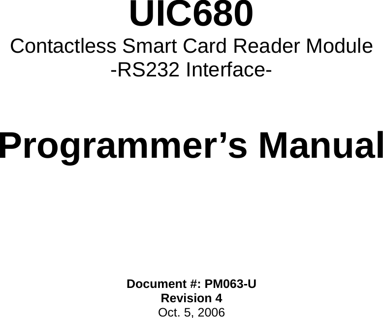
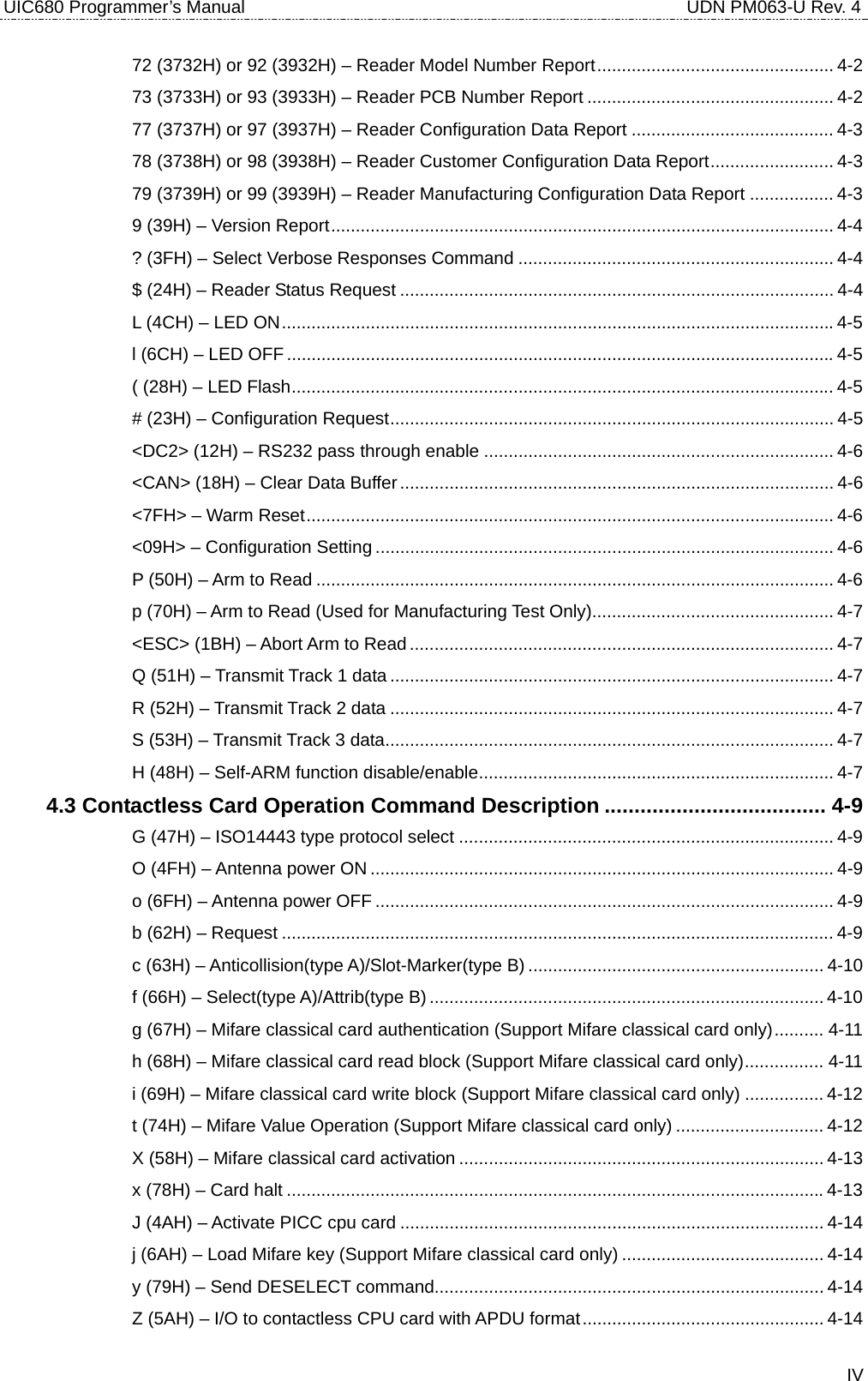
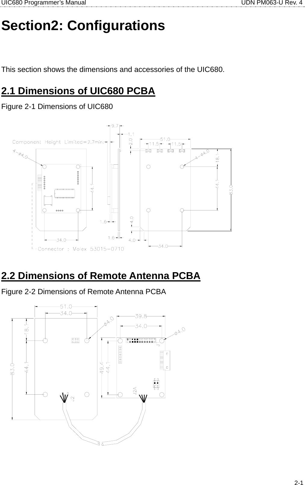
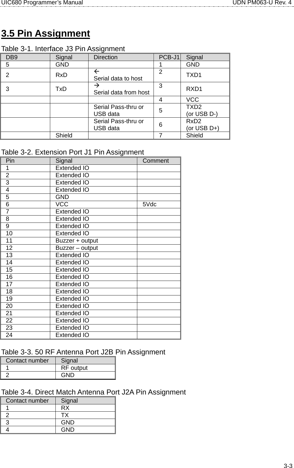
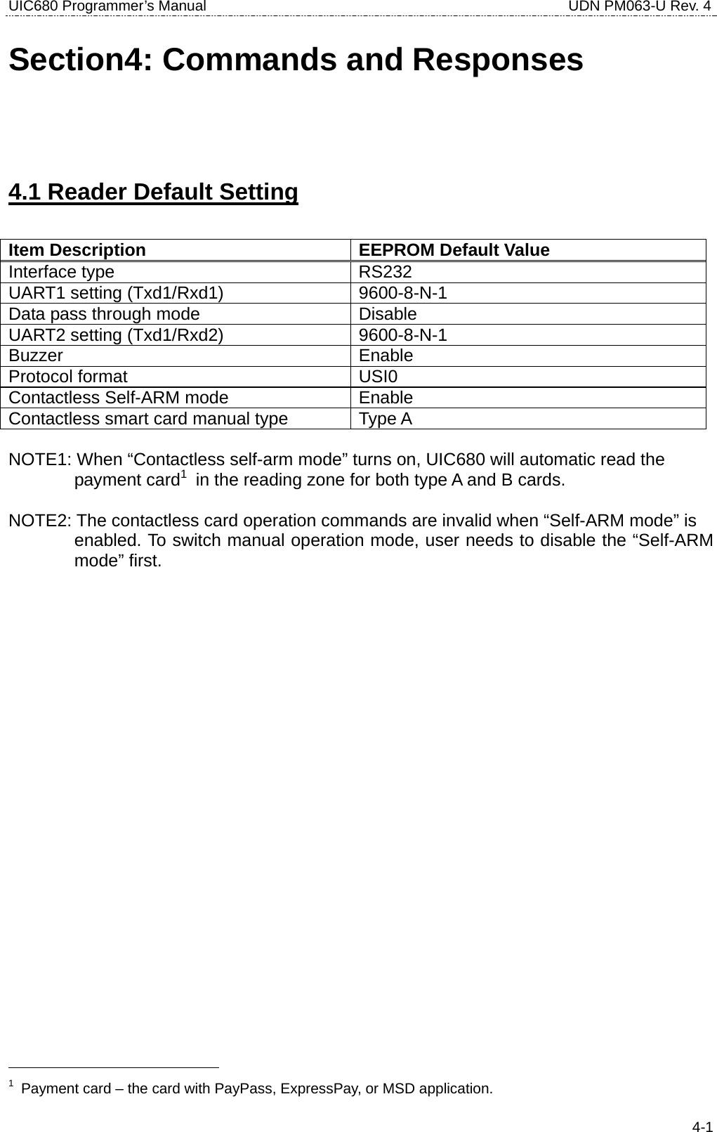
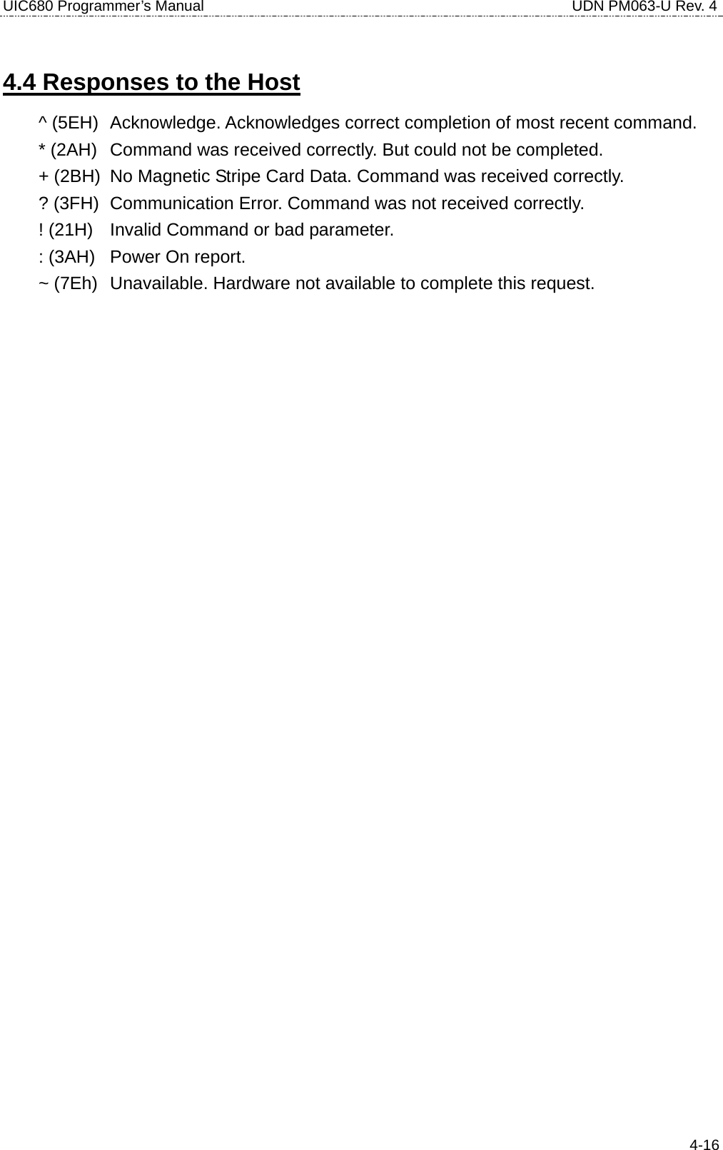
![UIC680 Programmer’s Manual UDN PM063-U Rev. 4 4-3• 77 (3737H) or 97 (3937H) – Reader Configuration Data Report COMMENT Transmit the reader configuration data. The data from the reader configuration area will be transmitted to the host as hex values with the command “77” [offset] [num]. The reader will return any or all the bytes from the reader configuration. The offset is an optional byte and the available value is from 0x00 to 0x3F. The num is an optional byte specifying the number of configuration bytes to be returned. If the offset and length bytes are omitted then the current configuration starting at offset 0 is transmitted. Example: BE 4C 03 03 00 00 00 61 30 35 30 35 30 36 82 00 00 00 00 00 00 00 00 00 00 00 00 00 00 00 00 00 00 00 00 00 00 00 00 00 00 00 00 00 00 00 00 00 00 00 00 00 00 00 00 00 3A 36 38 30 2D 52 48 00 • 78 (3738H) or 98 (3938H) – Reader Customer Configuration Data Report COMMENT Transmit the reader customer configuration data. The data from the reader customer configuration area of the EEPROM will be transmitted to the host as hex values with the command “78¨ [offset] [num]. The reader will return any or all the bytes from the reader configuration. The offset is an optional byte and the available value is from 0x00 to 0x3F. The num is an optional byte specifying the number of configuration bytes to be returned. If the offset and length bytes are omitted then the current configuration starting at offset 0 is transmitted. Example: 00 30 30 30 30 30 30 30 30 36 38 30 2D 52 45 56 31 03 04 03 02 00 3C 00 80 00 00 00 00 00 00 00 00 00 00 00 00 00 00 45 00 2B FF FF FF FF FF FF FF FF FF FF FF FF 3F 3F 12 FF 06 3F 05 13 50 03 • 79 (3739H) or 99 (3939H) – Reader Manufacturing Configuration Data Report COMMENT Transmit the reader manufacturing configuration data. The data from the reader manufacturing configuration area of the flash will be transmitted to the host as hex values with the command “79” [offset] [num]. The reader will return any or all the bytes from the reader configuration. The offset is an optional](https://usermanual.wiki/Uniform/UIC680/User-Guide-728418-Page-19.png)
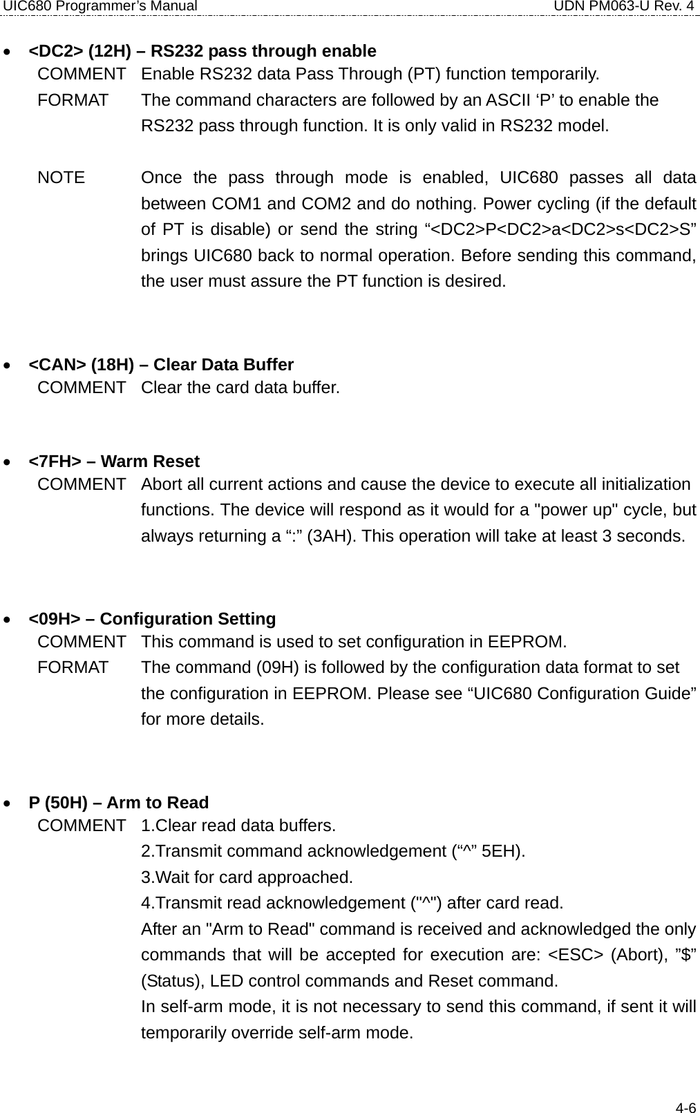
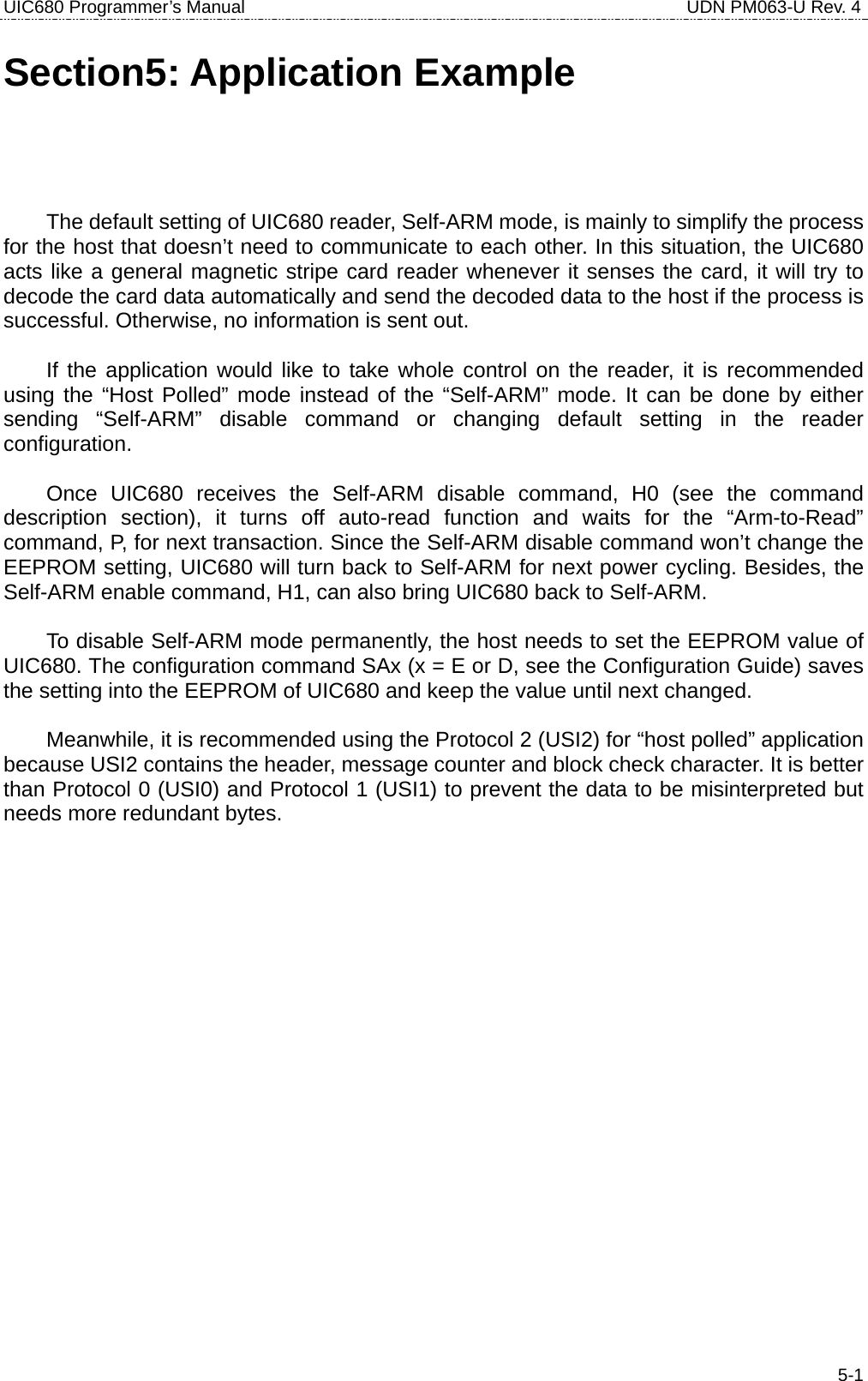
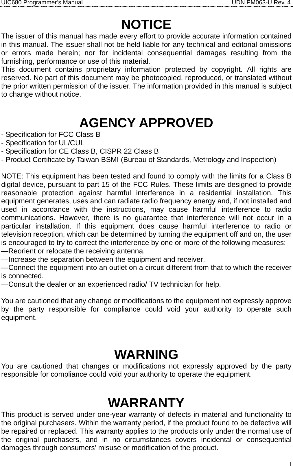
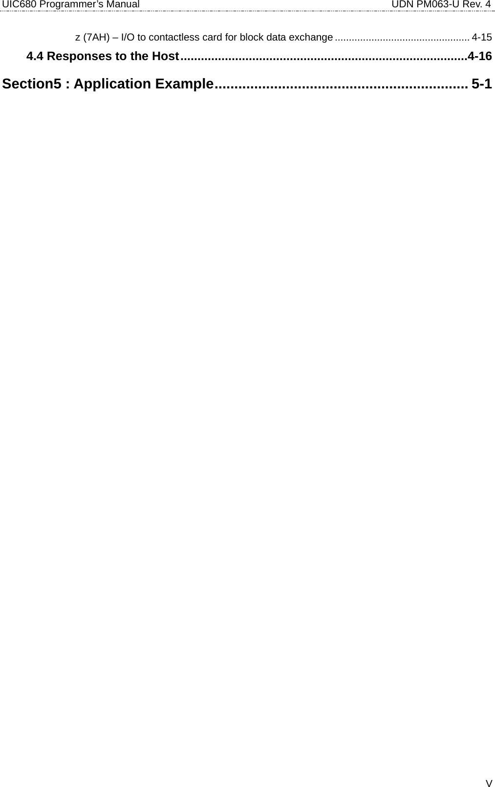
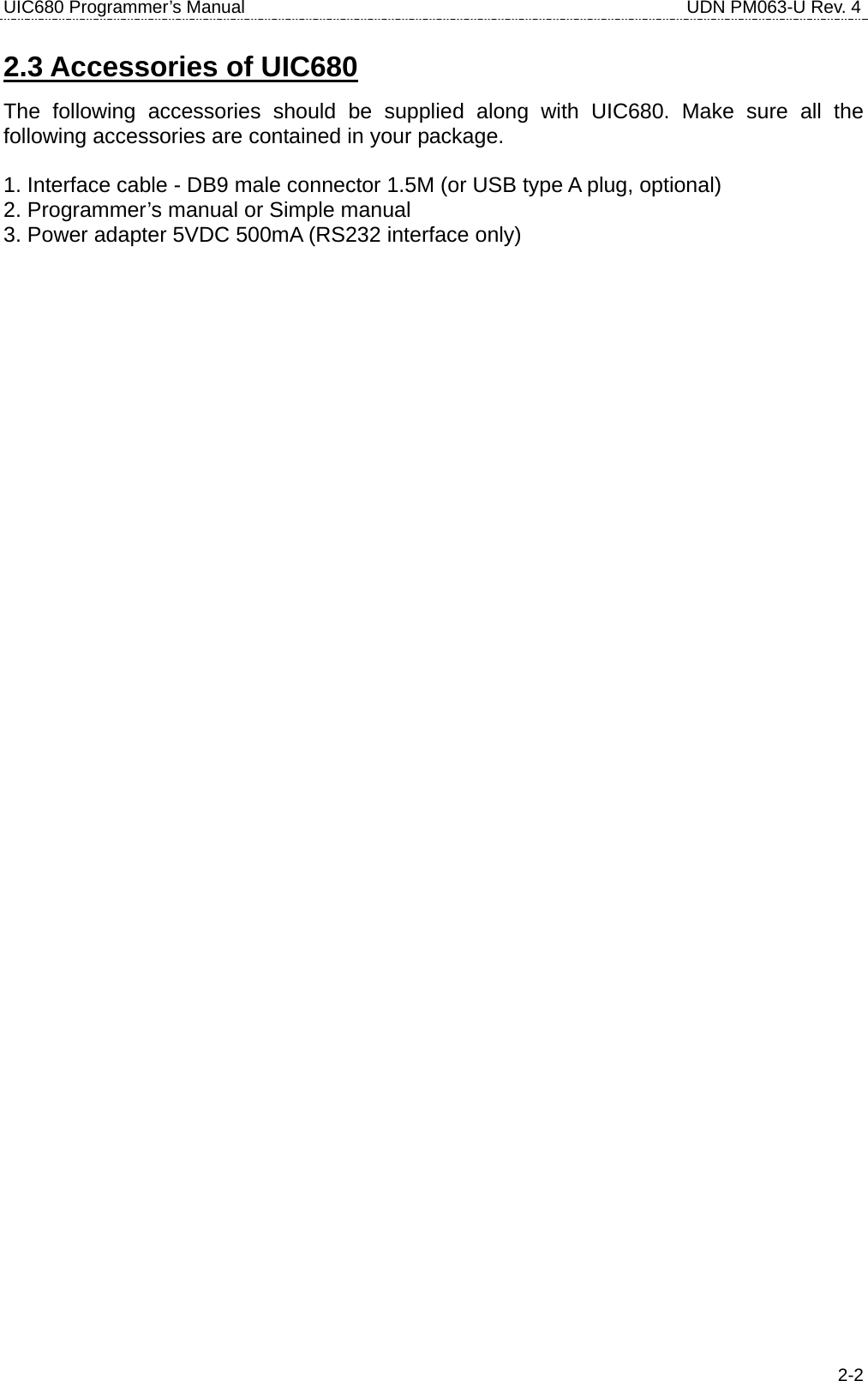
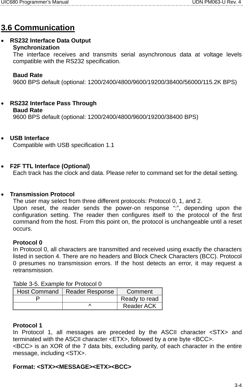
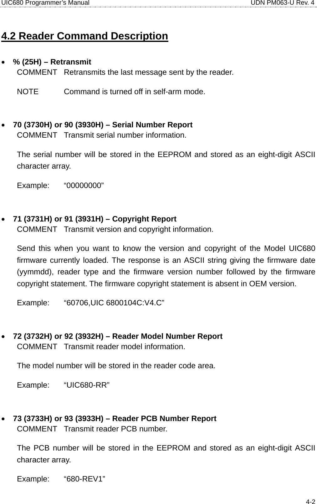
![UIC680 Programmer’s Manual UDN PM063-U Rev. 4 4-7• p (70H) – Arm to Read (Used for Manufacturing Test Only) COMMENT 1.Clear read data buffers. 2.Transmit command acknowledgement (“^” 5EH). 3.Wait for card read. 4.If the card media is detected a "(" (28H) byte is sent, when media detect goes inactive a “)” (29H) byte is sent. This is similar to the 'P' command but send ‘(‘ at start of magnetic stripe card data and ‘)’ at end. • <ESC> (1BH) – Abort Arm to Read COMMENT 1.Clear read data buffers. 2.Abort Arm to Read Command. 3.Transmit command acknowledge (“^” 5EH). • Q (51H) – Transmit Track 1 data • R (52H) – Transmit Track 2 data • S (53H) – Transmit Track 3 data COMMENT 1.Detect the card type automatically and process data in the read buffer. 2.If error is detected, transmit proper error response ('*' or '+'), refer to “Responses to the Host” section. 3.Else, transmit data in ASCII. • H (48H) – Self-ARM function disable/enable COMMENT Disable auto read function temporarily if Self-Arm is enabling. H [Enable/Disable, 1 byte] [Enable/Disable] 0 (30h, ASCII Hex) - Self-Arm disable 1 (31h, ASCII Hex) - Self-Arm enable NOTE UIC680 cannot perform the Self-ARM enable command for the contactless payment card reading under below conditions: 1.The payment card is decoded successful and the UIC680 is waiting the card to be removed from the reading zone. 2.The payment card is failed to decode and the UIC680 is waiting the card to be removed from the reading zone.](https://usermanual.wiki/Uniform/UIC680/User-Guide-728418-Page-23.png)
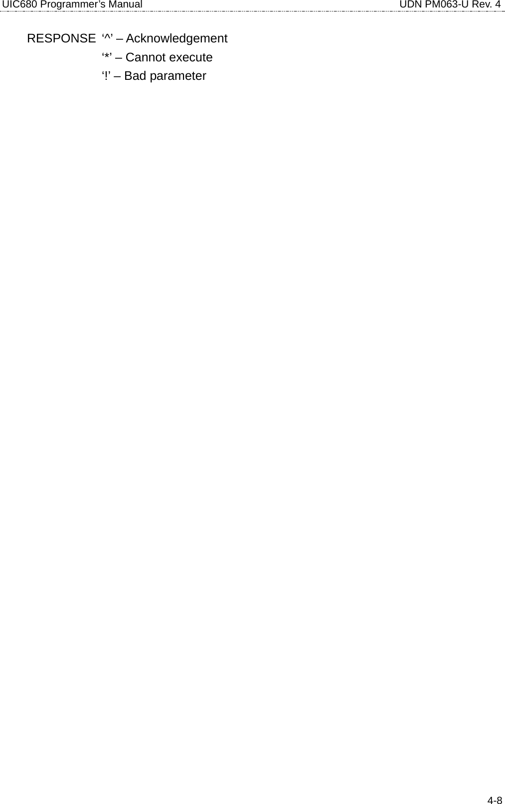
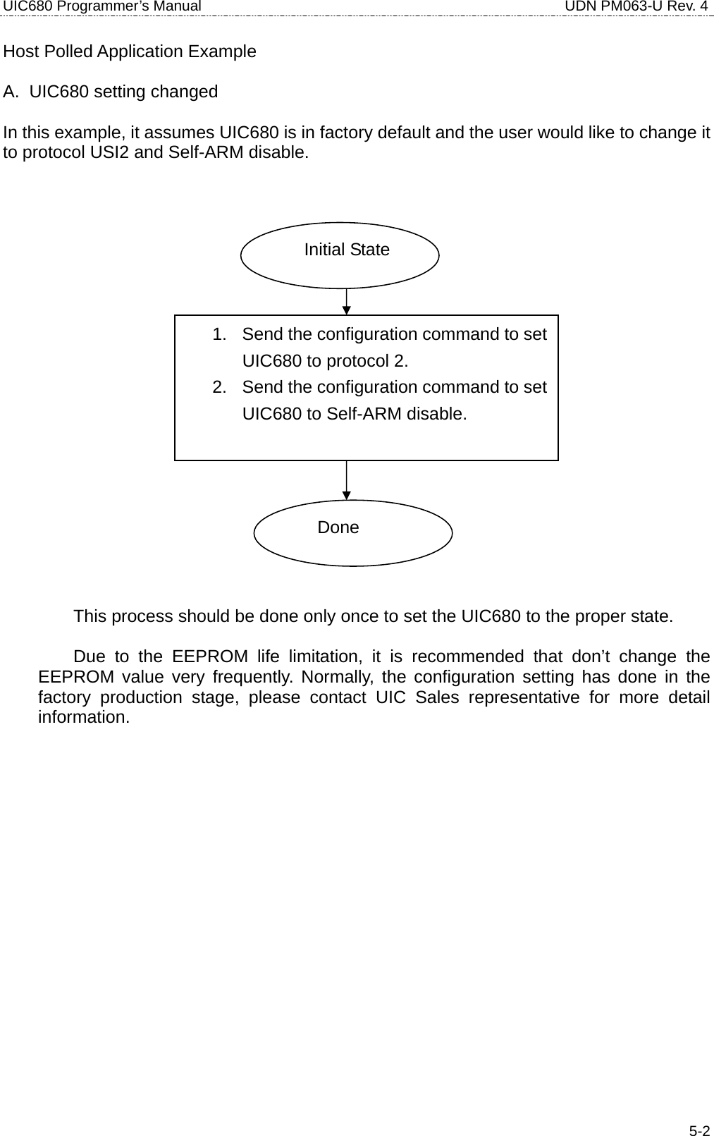
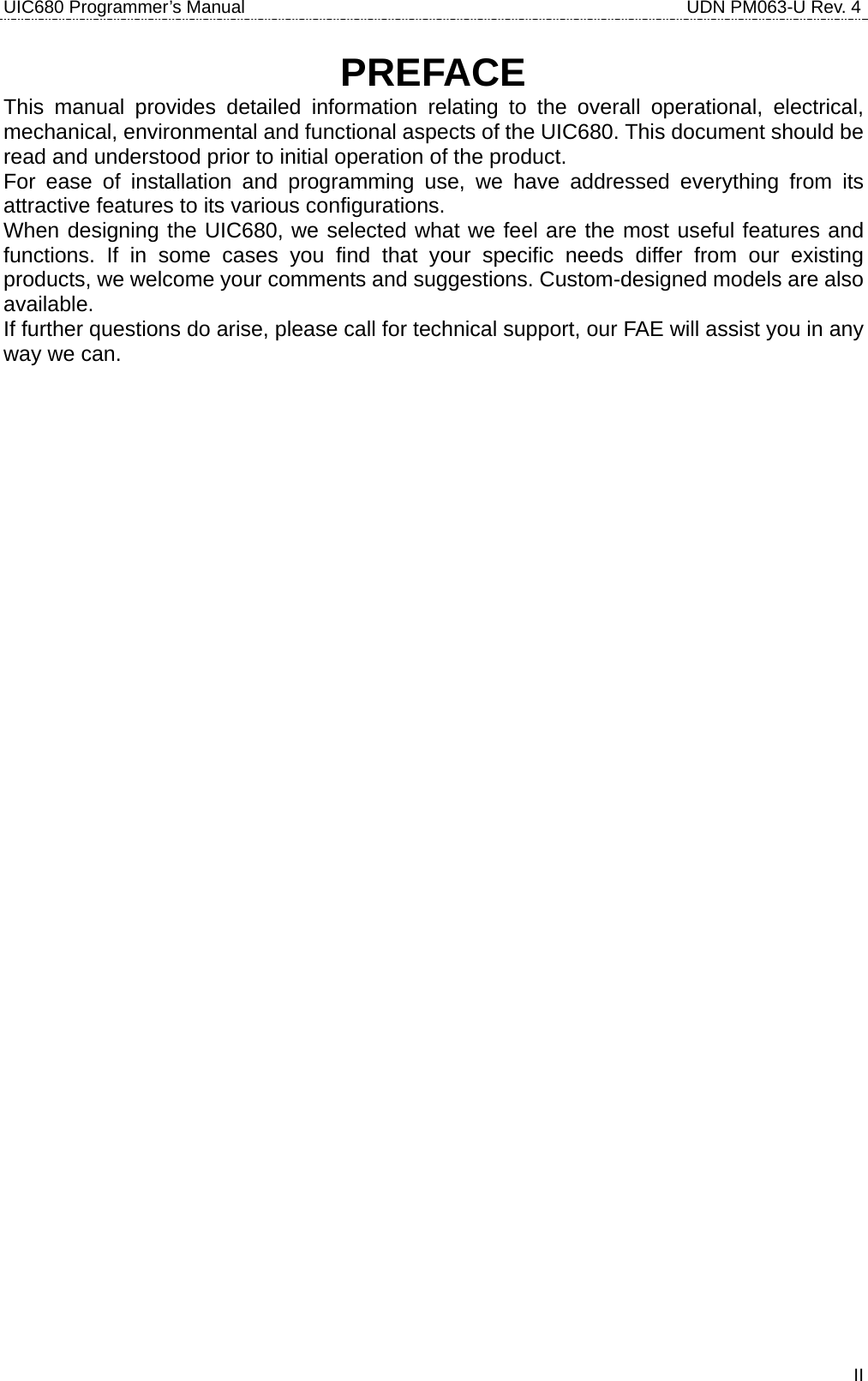
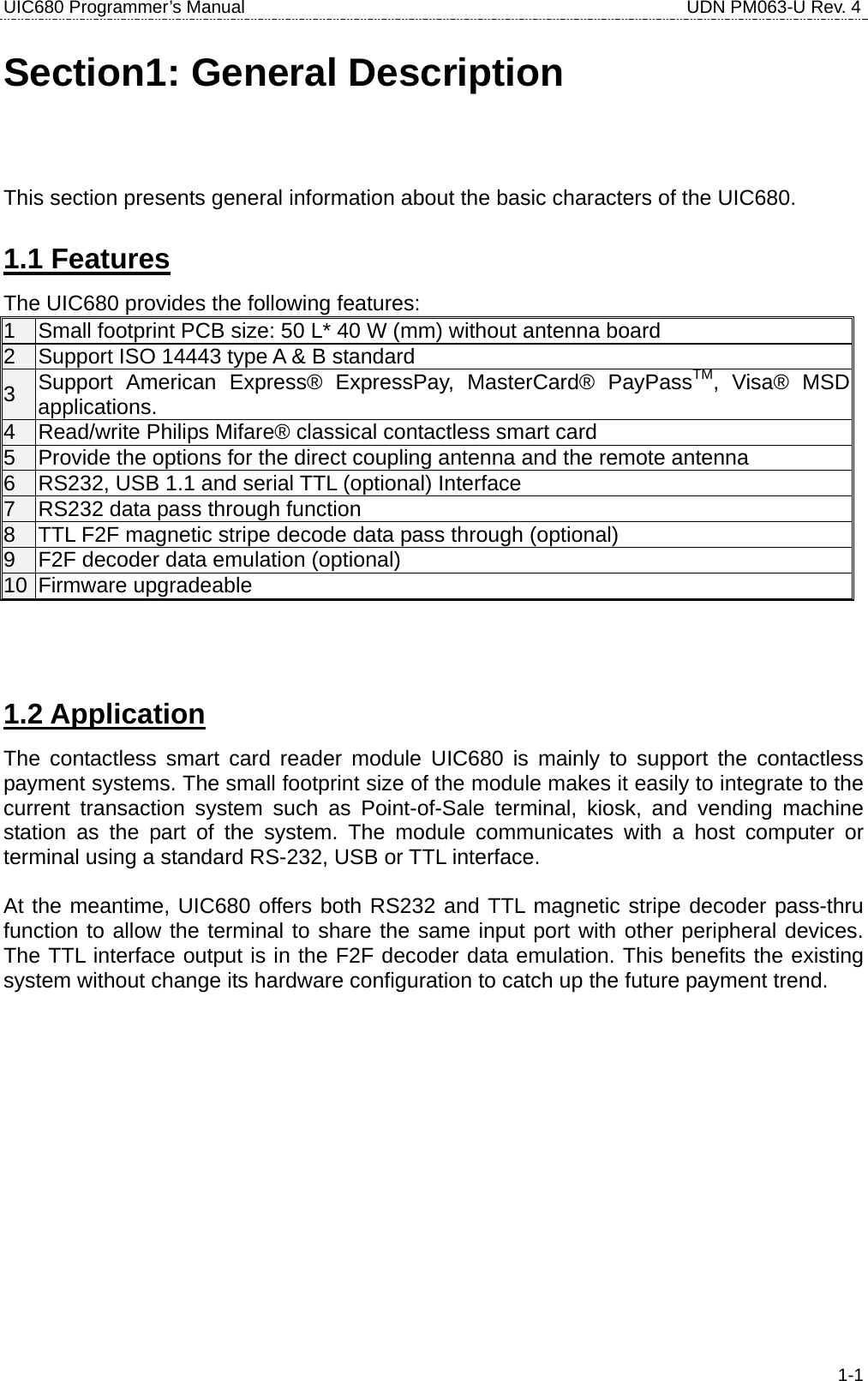
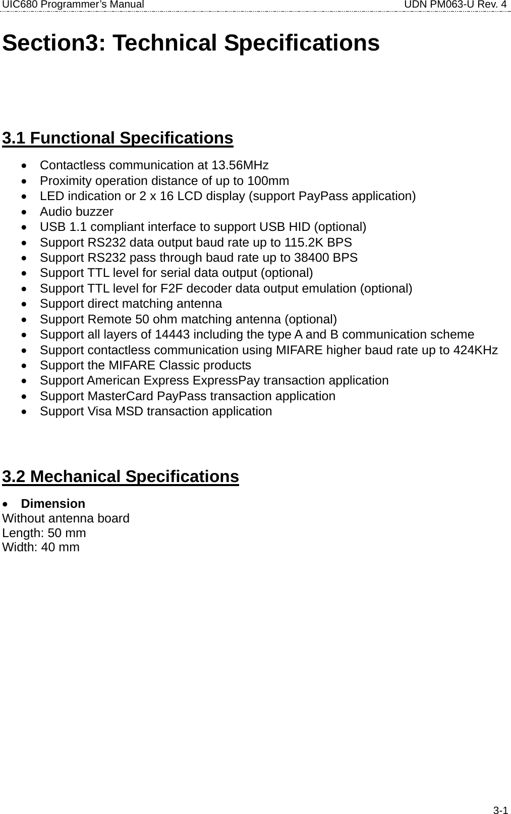
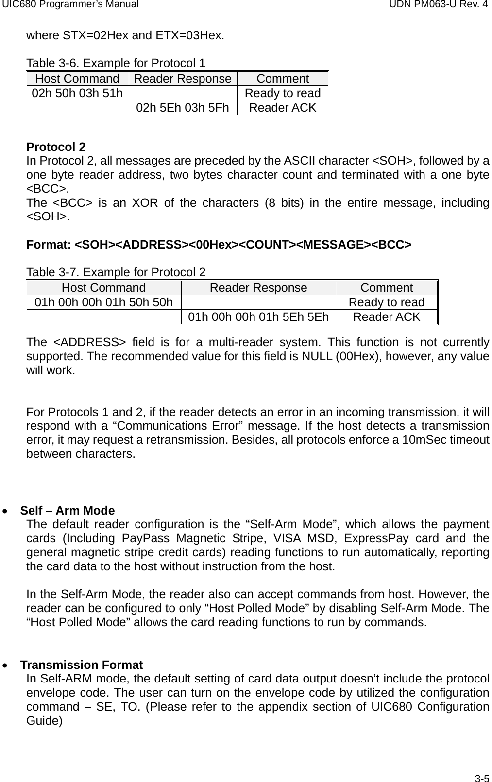
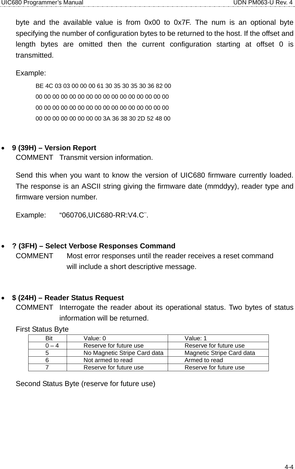
![UIC680 Programmer’s Manual UDN PM063-U Rev. 4 4-94.3 Contactless Card Operation Command Description • G (47H) – ISO14443 type protocol select COMMENT Select ISO 14443 type A or B which manual command operated. G[Type, 1 byte] [Type] 0 (30h, ASCII Hex) - ISO14443 A 4 (30h, ASCII Hex) - ISO14443 B The default contactless smart card type is type A after power up. RESPONSE ‘^’ – Acknowledgement ‘!’ – Bad parameter • O (4FH) – Antenna power ON COMMENT Apply power on the antenna. This command is for manual command operation. RESPONSE ‘^’ – Acknowledgement ‘*’ – Failed, the reader is in Self-Arm mode. The antenna power cannot be turned off. • o (6FH) – Antenna power OFF COMMENT Turn the antenna power off. RESPONSE ‘^’ – Acknowledgement ‘*’ – Failed, the reader is in Self-Arm mode. The antenna power cannot be turned off. • b (62H) – Request COMMENT Request command. b[Req command, 1 byte] - If reader is set to ISO14443 type A [Req command] (optional)](https://usermanual.wiki/Uniform/UIC680/User-Guide-728418-Page-25.png)
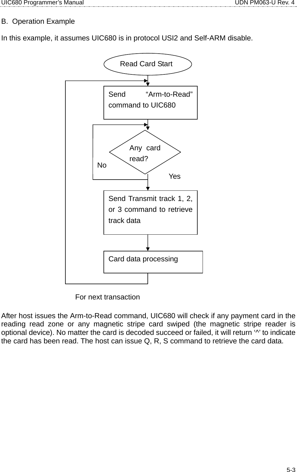
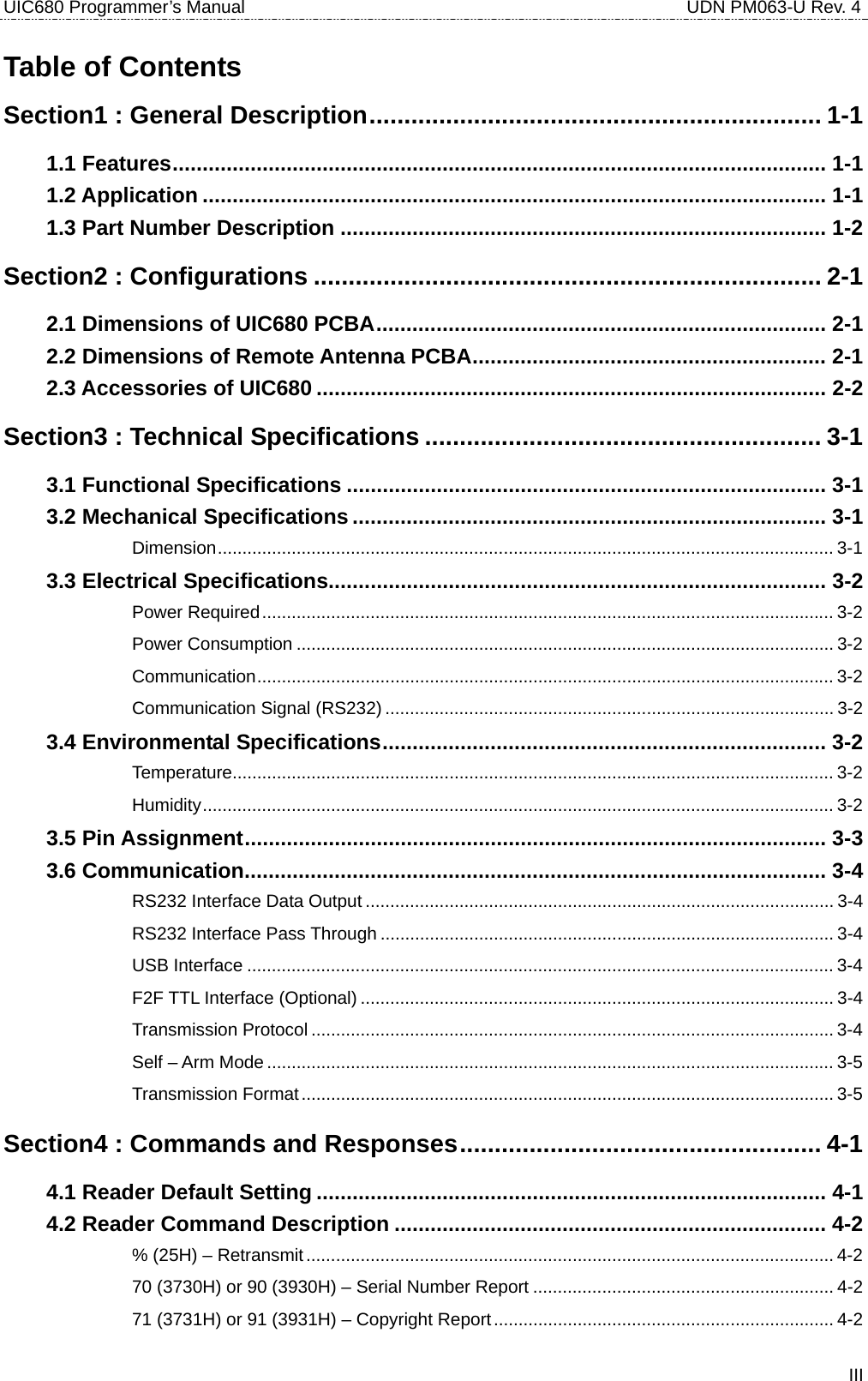
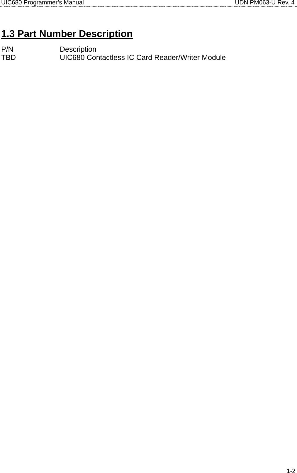
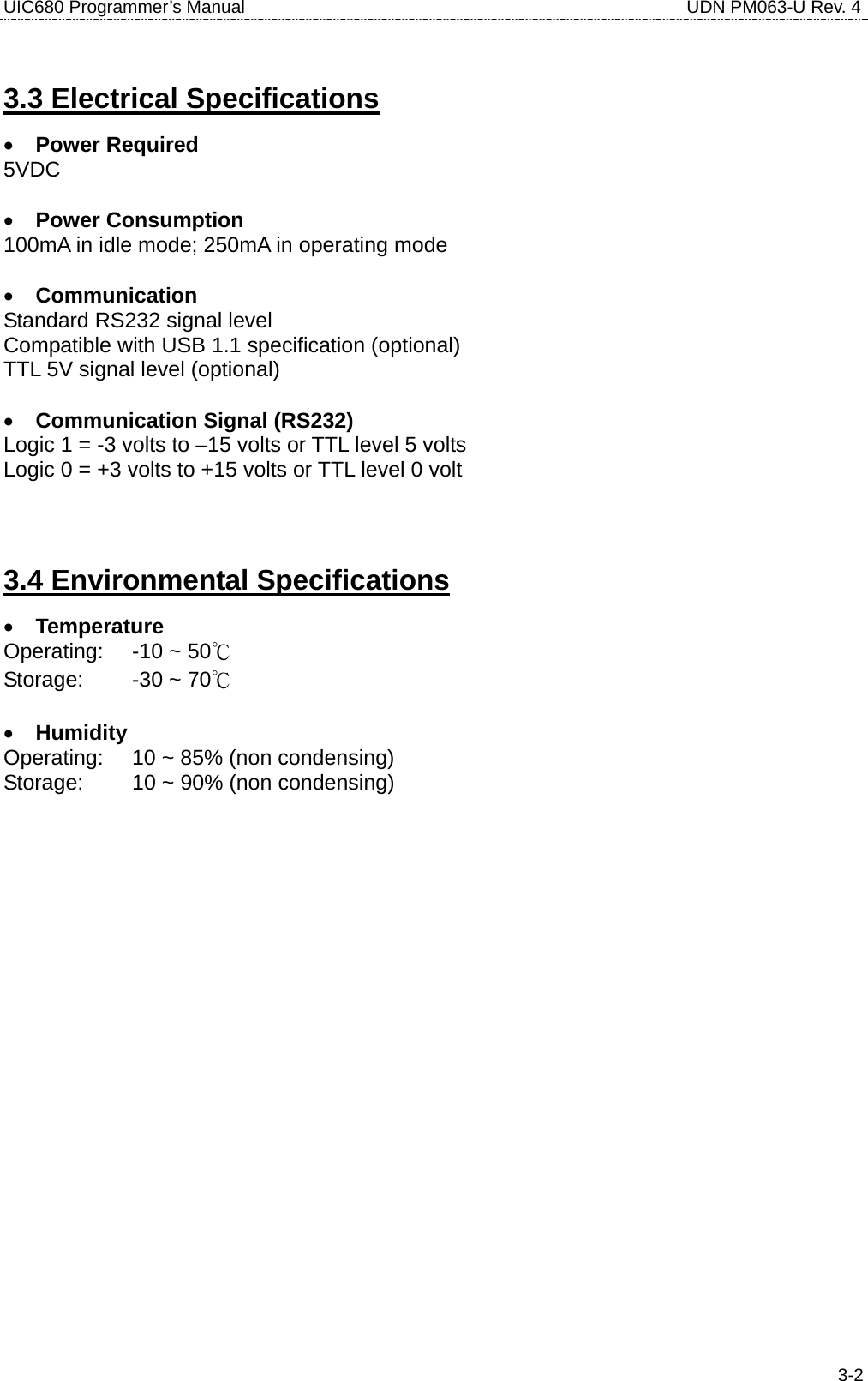
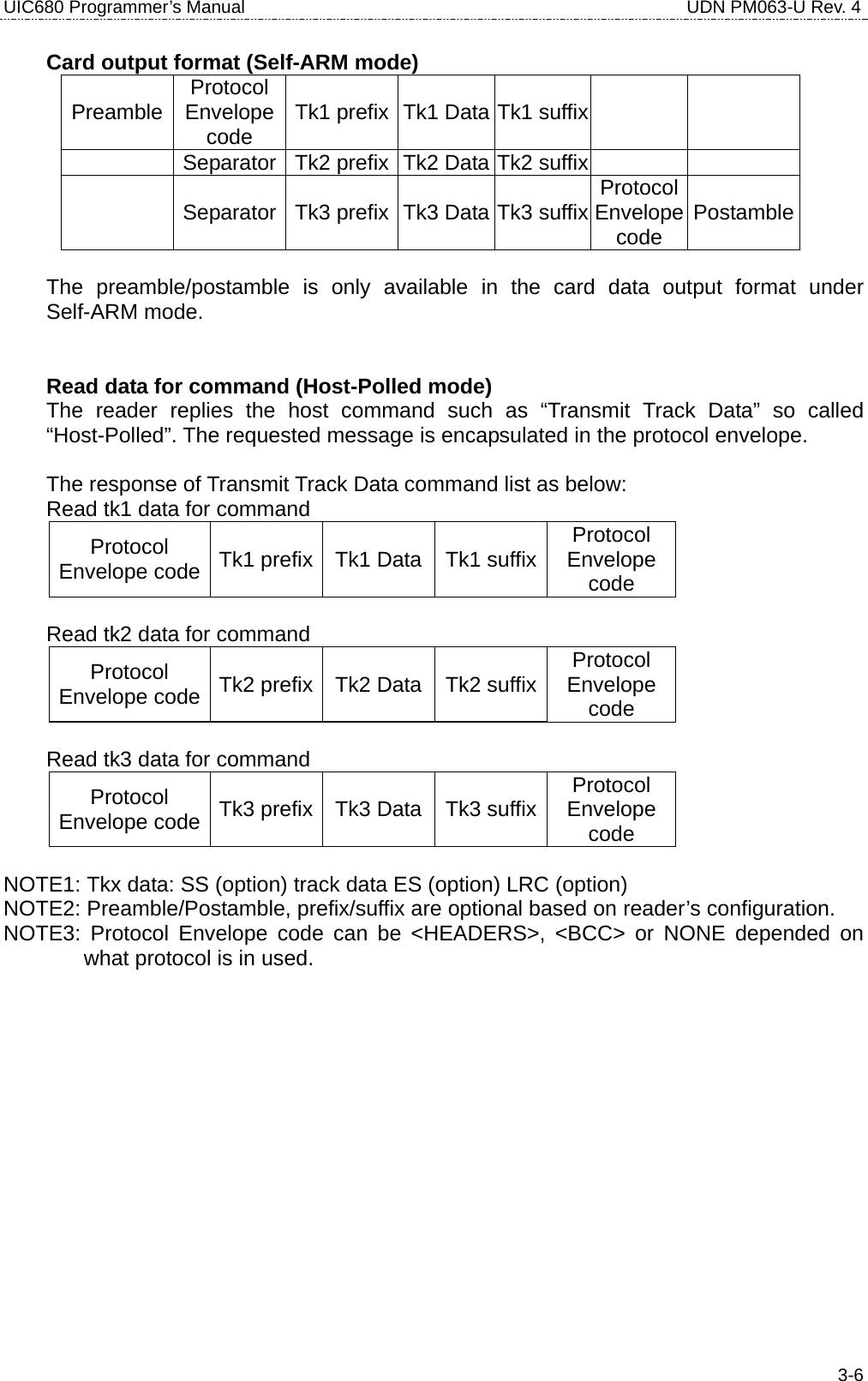
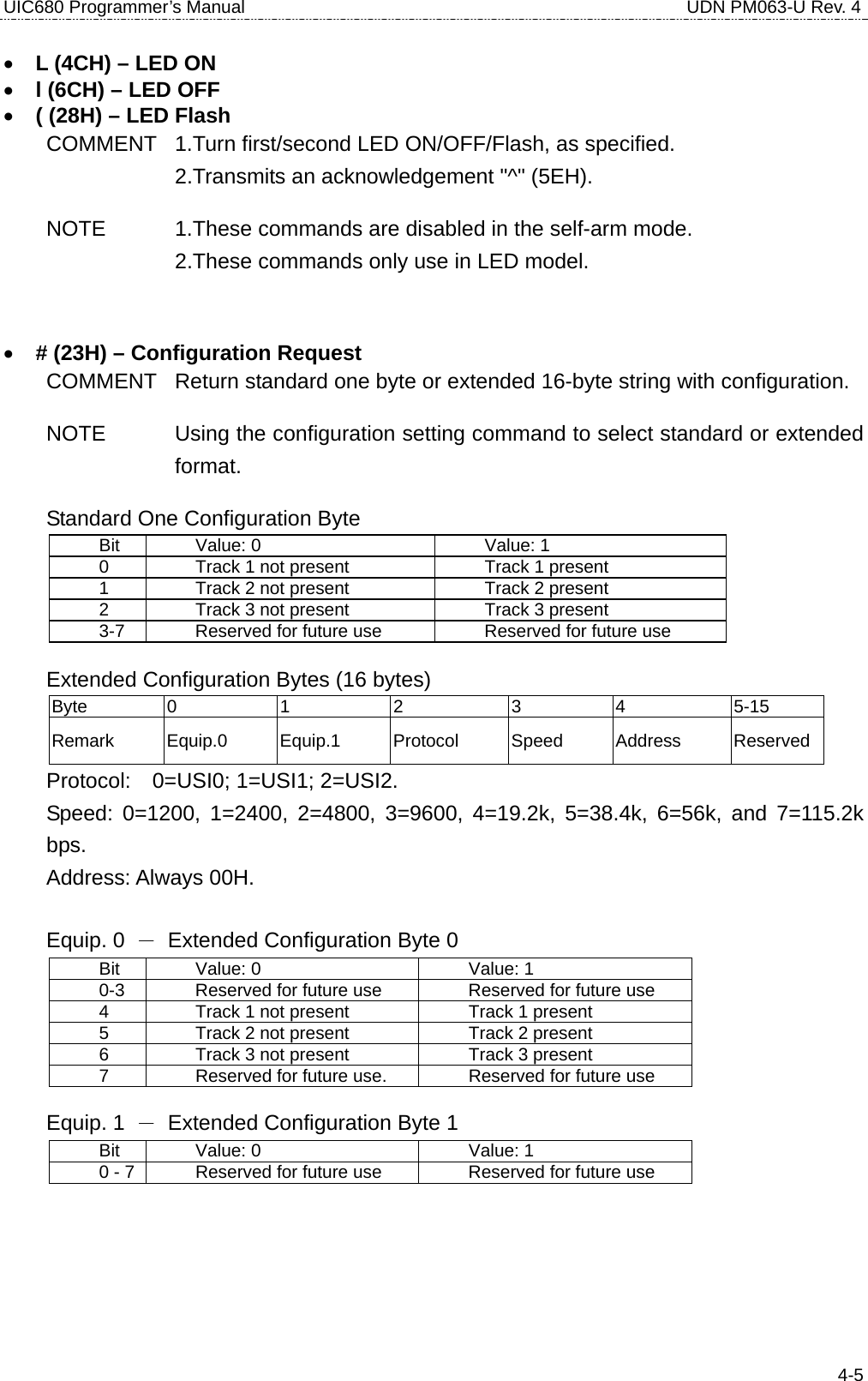
![UIC680 Programmer’s Manual UDN PM063-U Rev. 4 4-10The request command code is ISO14443 type A. It can be either 26 (REQA) or 52 (WUPA) NOTE If the [Req command] field does not appear in the request command, reader will set the request mode to WUPA automatically. b[AFI, 1 byte][Parameter, 1 byte] - If reader is set to ISO14443 type B [AFI](optional) - Binary hex (00h to FFh), please refer to ISO 14443-3 for the detailed information [Parameter](optional) - Binary hex (00h to FFh), please refer to 14443 for the detailed information. NOTE If the [AFI] and [Parameter] do not appear in the request command, reader will set the request mode to WUPB automatically. RESPONSE ATQA (2 bytes, type A, Binary Hex) or ATQB (16 bytes, type B, Binary Hex) if command executed successfully ‘*’ – No card response or No power on the antenna • c (63H) – Anticollision(type A)/Slot-Marker(type B) COMMENT In type A mode, the reader sends the Anti-collision command to the card. In type B mode, the reader sends the Slot-Marker command to the card. c – ISO 14443 type A c[APn] – ISO14443 type B [APn] – Anti-collision prefix byte.(type B only) NOTE Slot-Marker is not a mandatory command for type B card. RESPONSE If the command executed successfully, the reader returns PICC serial number for type A (Binary Hex) or PICC send ATQB (12 bytes, Binary Hex) for type B ‘*’ – No card response or or No power on the antenna ‘!’ – Bad parameter • f (66H) – Select(type A)/Attrib(type B) COMMENT In type A mode, the reader sends the SELECT command to the card. In type B mode, the reader sends the ATTRIB command to the card.](https://usermanual.wiki/Uniform/UIC680/User-Guide-728418-Page-26.png)
![UIC680 Programmer’s Manual UDN PM063-U Rev. 4 4-11RESPONSE If the command executed successfully, the reader returns ‘^’ + SAK( 1 byte) or ‘^’ + MBLI/CID(1 byte) ‘*’ – No card response or No power on the antenna • g (67H) – Mifare classical card authentication (Support Mifare classical card only) COMMENT Mifare classical card authentication. g[Block number, 3 bytes][Key number, 1 byte][Key type] Authenticate the card with the key stored in EEPROM. or g[Block number, 3 bytes] ][Key type] [Key, 12 bytes] Authenticate the card with the key in [key field]. [Block number] There are two types of block format 000 to 255 (30h30h30h to 32h35h35h, ASCII Hex) or B<00><00> to B<00><FF> (42h00h00h to 42h00hFFh, ASCII Hex) [Key number] 0 to 4 (30h to 35h, ASCII Hex) [Key] 0 to 9 or A to F (30h - 39h or 41h - 46h, ASCII Hex) [Key type] A or B (41h or 42h) RESPONSE ‘^’ – acknowledgement ‘*’ – No card response or No power on the antenna • h (68H) – Mifare classical card read block (Support Mifare classical card only) COMMENT Mifare classical card read command. h[Block number, 3 bytes]](https://usermanual.wiki/Uniform/UIC680/User-Guide-728418-Page-27.png)
![UIC680 Programmer’s Manual UDN PM063-U Rev. 4 4-12[Block number] There are two types of block format 000 to 255 (30h30h30h to 32h35h35h, ASCII Hex) or B<00><00> to B<00><FF> (42h00h00h to 42h00hFFh, ASCII Hex) RESPONSE block data (16 bytes, Binary Hex) if command executed successfully ‘*’ – No card response or No power on the antenna • i (69H) – Mifare classical card write block (Support Mifare classical card only) COMMENT Mifare classical card write command. i[Block number, 3 bytes][Block data, 4 bytes or 16 bytes] [Block number] There are three types of block number format 000 to 255 (30h30h30h to 32h35h35h, ASCII Hex) General Mifare Block or B<00><00> to B<00><FF> (42h00h00h to 42h00hFFh, ASCII Hex) General Mifare Block or U<00><00> to B<00><FF> (55h00h00h to 42h00hFFh, ASCII Hex) Mifare Ultralight [Block data] For Mifare Ultralight, the block data should be 4 bytes, others are using 16 bytes block data. RESPONSE ‘^’ – Acknowledgement ‘*’ – No card response or No power on the antenna • t (74H) – Mifare Value Operation (Support Mifare classical card only) COMMENT Mifare classical card value operation command. t[Block number, 3 bytes][Operation mode, 1 byte][Value, 4 bytes][transfer block, 3 bytes]](https://usermanual.wiki/Uniform/UIC680/User-Guide-728418-Page-28.png)
![UIC680 Programmer’s Manual UDN PM063-U Rev. 4 4-13[Block number] There are two types of block number format 000 to 255 (30h30h30h to 32h35h35h, ASCII Hex) or B<00><00> to B<00><FF> (42h00h00h to 42h00hFFh, ASCII Hex) [Operation mode] 0 (30h, ASCII Hex) – Decrement 1 (31h, ASCII Hex) – Increment 2 (32h, ASCII Hex) – Restore 3 (33h, ASCII Hex) – Decrement and transfer to the different block. 4 (34h, ASCII Hex) – Create Mifare Value in the block. [Value] Binary Hex from 0h to FFh For option 3 only, the data format is same as [block number] RESPONSE ‘^’ – Acknowledgement ‘*’ – No card response or No power on the antenna ‘!’ – Bad parameter • X (58H) – Mifare classical card activation COMMENT Perform request/anticollision/select command to activate the card. It is also can be used for any ISO14443 compatible card. RESPONSE ATQA/SAK/serial number if the command executed successfully for type A card ATQB (12 bytes) if the command executed successfully for type B card ‘*’ – No card response or No power on the antenna • x (78H) – Card halt COMMENT Card halt command. RESPONSE ‘^’ – acknowledgement ‘*’ – No card response or No power on the antenna](https://usermanual.wiki/Uniform/UIC680/User-Guide-728418-Page-29.png)
![UIC680 Programmer’s Manual UDN PM063-U Rev. 4 4-14• J (4AH) – Activate PICC cpu card COMMENT Activate PICC cpu card command. The Antenna POWER ON command has to be sent first. RESPONSE ATS (type A) or PUPI (type B) if command executed successfully ‘*’ – No card response or No power on the antenna • j (6AH) – Load Mifare key (Support Mifare classical card only) COMMENT Save up to 5 key sets for Mifare classical card application NOTE For security reason, there is no way to retrieve the key back. j[Key number, 1 byte][Key data, 12 bytes] [Key number] 0 to 4 (30h to 39h, ASCII Hex) [Key data] 0 to 9 or A to F (30h - 39h or 41h - 46h, ASCII Hex) RESPONSE ‘^’ – acknowledgement ‘*’ – No card response or No power on the antenna • y (79H) – Send DESELECT command COMMENT Send ISO14443 layer 4 DESELECT command to card RESPONSE ‘^’ – acknowledgement ‘*’ – No card response or No power on the antenna • Z (5AH) – I/O to contactless CPU card with APDU format COMMENT The command is used to pass an APDU to the card where both data and an ISO status are expected in the response. Z[APDU, variant, 262 bytes max] [APDU] Binary hex (00h to FFh) If successful, the data from the ICC and the two byte SW1/SW2 ISO 7816-4 response are returned.](https://usermanual.wiki/Uniform/UIC680/User-Guide-728418-Page-30.png)
![UIC680 Programmer’s Manual UDN PM063-U Rev. 4 4-15If unsuccessful, reader transmits '*'. APDU Command Structure CLA INS P1 P2 P3 Lc or Le Data (If Lc present) APDU Response Structure Data (optional) SW1 SW2 • z (7AH) – I/O to contactless card for block data exchange COMMENT The command is used to pass a block data to a card. z[CRC mode, 1 bytes][Wait time, 4 bytes][Block data, 384 bytes max.] [CRC mode] 0 (30h, ASCII Hex) – Block data contain 2 bytes CRC and enable CRC transmission. 1 (31h, ASCII Hex) – No CRC in block data and disable CRC transmission. [Wait time] 0000 to 9999 (30h30h30h30h to 39h39h39h39h, ASCII Hex) Waiting time in ms. [Block data] Binary hex (00h to FFh), Maximum accepts 384 bytes. If successful, the data from the ICC are returned. If unsuccessful, reader transmits '*'.](https://usermanual.wiki/Uniform/UIC680/User-Guide-728418-Page-31.png)