Uniform UIC681 Contactless Card Reader User Manual
Uniform Industrial Corp. Contactless Card Reader Users Manual
Uniform >
Users Manual
UIC681
Contactless Smart Card Reader Module
-RS232 Interface-
Programmer’s Manual
Document #: PM063-U
Revision 4
Oct. 5, 2006

UIC681 Programmer’s Manual UDN PM063-U Rev. 4
I
NOTICE
The issuer of this manual has made every effort to provide accurate information contained
in this manual. The issuer shall not be held liable for any technical and editorial omissions
or errors made herein; nor for incidental consequential damages resulting from the
furnishing, performance or use of this material.
This document contains proprietary information protected by copyright. All rights are
reserved. No part of this document may be photocopied, reproduced, or translated without
the prior written permission of the issuer. The information provided in this manual is subject
to change without notice.
AGENCY APPROVED
- Specification for FCC Class B
- Specification for UL/CUL
- Specification for CE Class B, CISPR 22 Class B
- Product Certificate by Taiwan BSMI (Bureau of Standards, Metrology and Inspection)
NOTE: This equipment has been tested and found to comply with the limits for a Class B
digital device, pursuant to part 15 of the FCC Rules. These limits are designed to provide
reasonable protection against harmful interference in a residential installation. This
equipment generates, uses and can radiate radio frequency energy and, if not installed and
used in accordance with the instructions, may cause harmful interference to radio
communications. However, there is no guarantee that interference will not occur in a
particular installation. If this equipment does cause harmful interference to radio or
television reception, which can be determined by turning the equipment off and on, the user
is encouraged to try to correct the interference by one or more of the following measures:
—Reorient or relocate the receiving antenna.
—Increase the separation between the equipment and receiver.
—Connect the equipment into an outlet on a circuit different from that to which the receiver
is connected.
—Consult the dealer or an experienced radio/ TV technician for help.
You are cautioned that any change or modifications to the equipment not expressly approve
by the party responsible for compliance could void your authority to operate such
equipment.
WARNING
You are cautioned that changes or modifications not expressly approved by the party
responsible for compliance could void your authority to operate the equipment.
WARRANTY
This product is served under one-year warranty of defects in material and functionality to
the original purchasers. Within the warranty period, if the product found to be defective will
be repaired or replaced. This warranty applies to the products only under the normal use of
the original purchasers, and in no circumstances covers incidental or consequential
damages through consumers’ misuse or modification of the product.

UIC681 Programmer’s Manual UDN PM063-U Rev. 4
II
PREFACE
This manual provides detailed information relating to the overall operational, electrical,
mechanical, environmental and functional aspects of the UIC681. This document should be
read and understood prior to initial operation of the product.
For ease of installation and programming use, we have addressed everything from its
attractive features to its various configurations.
When designing the UIC681, we selected what we feel are the most useful features and
functions. If in some cases you find that your specific needs differ from our existing
products, we welcome your comments and suggestions. Custom-designed models are also
available.
If further questions do arise, please call for technical support, our FAE will assist you in any
way we can.

UIC681 Programmer’s Manual UDN PM063-U Rev. 4
III
Table of Contents
Section1 : General Description................................................................. 1-1
1.1 Features............................................................................................................. 1-1
1.2 Application ........................................................................................................ 1-1
1.3 Part Number Description ................................................................................. 1-2
Section2 : Configurations ......................................................................... 2-1
2.1 Dimensions of UIC681 PCBA........................................................................... 2-1
2.2 Dimensions of Remote Antenna PCBA........................................................... 2-1
2.3 Accessories of UIC681 ..................................................................................... 2-2
Section3 : Technical Specifications ......................................................... 3-1
3.1 Functional Specifications ................................................................................ 3-1
3.2 Mechanical Specifications ............................................................................... 3-1
Dimension............................................................................................................................. 3-1
3.3 Electrical Specifications................................................................................... 3-2
Power Required.................................................................................................................... 3-2
Power Consumption ............................................................................................................. 3-2
Communication..................................................................................................................... 3-2
Communication Signal (RS232) ........................................................................................... 3-2
3.4 Environmental Specifications.......................................................................... 3-2
Temperature.......................................................................................................................... 3-2
Humidity................................................................................................................................ 3-2
3.5 Pin Assignment................................................................................................. 3-3
3.6 Communication................................................................................................. 3-4
RS232 Interface Data Output ............................................................................................... 3-4
RS232 Interface Pass Through ............................................................................................ 3-4
USB Interface ....................................................................................................................... 3-4
F2F TTL Interface (Optional) ................................................................................................ 3-4
Transmission Protocol .......................................................................................................... 3-4
Self – Arm Mode ................................................................................................................... 3-5
Transmission Format............................................................................................................ 3-5
Section4 : Commands and Responses.................................................... 4-1
4.1 Reader Default Setting ..................................................................................... 4-1
4.2 Reader Command Description ........................................................................ 4-2
% (25H) – Retransmit........................................................................................................... 4-2
70 (3730H) or 90 (3930H) – Serial Number Report ............................................................. 4-2
71 (3731H) or 91 (3931H) – Copyright Report..................................................................... 4-2

UIC681 Programmer’s Manual UDN PM063-U Rev. 4
IV
72 (3732H) or 92 (3932H) – Reader Model Number Report................................................ 4-2
73 (3733H) or 93 (3933H) – Reader PCB Number Report .................................................. 4-2
77 (3737H) or 97 (3937H) – Reader Configuration Data Report ......................................... 4-3
78 (3738H) or 98 (3938H) – Reader Customer Configuration Data Report......................... 4-3
79 (3739H) or 99 (3939H) – Reader Manufacturing Configuration Data Report ................. 4-3
9 (39H) – Version Report...................................................................................................... 4-4
? (3FH) – Select Verbose Responses Command ................................................................ 4-4
$ (24H) – Reader Status Request ........................................................................................ 4-4
L (4CH) – LED ON................................................................................................................4-5
l (6CH) – LED OFF ...............................................................................................................4-5
( (28H) – LED Flash.............................................................................................................. 4-5
# (23H) – Configuration Request.......................................................................................... 4-5
<DC2> (12H) – RS232 pass through enable ....................................................................... 4-6
<CAN> (18H) – Clear Data Buffer........................................................................................ 4-6
<7FH> – Warm Reset........................................................................................................... 4-6
<09H> – Configuration Setting ............................................................................................. 4-6
P (50H) – Arm to Read ......................................................................................................... 4-6
p (70H) – Arm to Read (Used for Manufacturing Test Only)................................................. 4-7
<ESC> (1BH) – Abort Arm to Read ...................................................................................... 4-7
Q (51H) – Transmit Track 1 data .......................................................................................... 4-7
R (52H) – Transmit Track 2 data .......................................................................................... 4-7
S (53H) – Transmit Track 3 data........................................................................................... 4-7
H (48H) – Self-ARM function disable/enable........................................................................ 4-7
4.3 Contactless Card Operation Command Description ..................................... 4-9
G (47H) – ISO14443 type protocol select ............................................................................ 4-9
O (4FH) – Antenna power ON .............................................................................................. 4-9
o (6FH) – Antenna power OFF ............................................................................................. 4-9
b (62H) – Request ................................................................................................................ 4-9
c (63H) – Anticollision(type A)/Slot-Marker(type B) ............................................................ 4-10
f (66H) – Select(type A)/Attrib(type B)................................................................................ 4-10
g (67H) – Mifare classical card authentication (Support Mifare classical card only).......... 4-11
h (68H) – Mifare classical card read block (Support Mifare classical card only)................ 4-11
i (69H) – Mifare classical card write block (Support Mifare classical card only) ................ 4-12
t (74H) – Mifare Value Operation (Support Mifare classical card only) .............................. 4-12
X (58H) – Mifare classical card activation .......................................................................... 4-13
x (78H) – Card halt .............................................................................................................4-13
J (4AH) – Activate PICC cpu card ...................................................................................... 4-14
j (6AH) – Load Mifare key (Support Mifare classical card only) ......................................... 4-14
y (79H) – Send DESELECT command............................................................................... 4-14
Z (5AH) – I/O to contactless CPU card with APDU format................................................. 4-14

UIC681 Programmer’s Manual UDN PM063-U Rev. 4
V
z (7AH) – I/O to contactless card for block data exchange ................................................ 4-15
4.4 Responses to the Host....................................................................................4-16
Section5 : Application Example................................................................ 5-1

UIC681 Programmer’s Manual UDN PM063-U Rev. 4
1-1
Section1: General Description
This section presents general information about the basic characters of the UIC681.
1.1 Features
The UIC681 provides the following features:
1 Small footprint PCB size: 50 L* 40 W (mm) without antenna board
2 Support ISO 14443 type A & B standard
3 Support American Express® ExpressPay, MasterCard® PayPassTM, Visa® MSD
applications.
4 Read/write Philips Mifare® classical contactless smart card
5 Provide the options for the direct coupling antenna and the remote antenna
6 RS232, USB 1.1 and serial TTL (optional) Interface
7 RS232 data pass through function
8 TTL F2F magnetic stripe decode data pass through (optional)
9 F2F decoder data emulation (optional)
10 Firmware upgradeable
1.2 Application
The contactless smart card reader module UIC681 is mainly to support the contactless
payment systems. The small footprint size of the module makes it easily to integrate to the
current transaction system such as Point-of-Sale terminal, kiosk, and vending machine
station as the part of the system. The module communicates with a host computer or
terminal using a standard RS-232, USB or TTL interface.
At the meantime, UIC681 offers both RS232 and TTL magnetic stripe decoder pass-thru
function to allow the terminal to share the same input port with other peripheral devices.
The TTL interface output is in the F2F decoder data emulation. This benefits the existing
system without change its hardware configuration to catch up the future payment trend.

UIC681 Programmer’s Manual UDN PM063-U Rev. 4
1-2
1.3 Part Number Description
P/N Description
TBD UIC681 Contactless IC Card Reader/Writer Module
UIC681 Programmer’s Manual UDN PM063-U Rev. 4
2-1
Section2: Configurations
This section shows the dimensions and accessories of the UIC681.
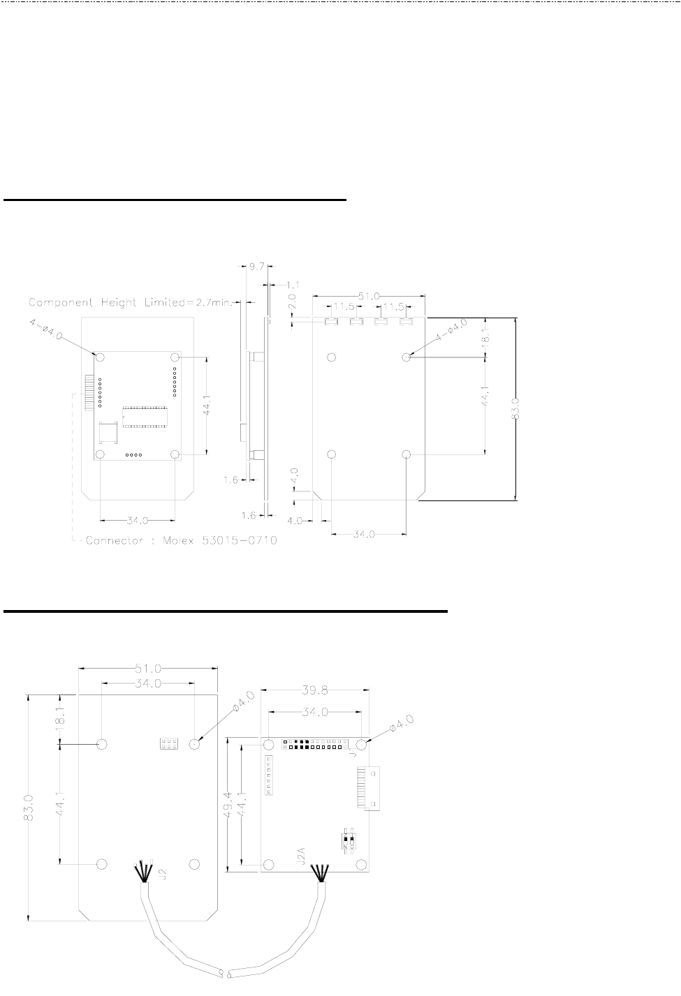
2.1 Dimensions of UIC681 PCBA
Figure 2-1 Dimensions of UIC681
2.2 Dimensions of Remote Antenna PCBA
Figure 2-2 Dimensions of Remote Antenna PCBA

UIC681 Programmer’s Manual UDN PM063-U Rev. 4
2-2
2.3 Accessories of UIC681
The following accessories should be supplied along with UIC681. Make sure all the
following accessories are contained in your package.
1. Interface cable - DB9 male connector 1.5M (or USB type A plug, optional)
2. Programmer’s manual or Simple manual
3. Power adapter 5VDC 500mA (RS232 interface only)

UIC681 Programmer’s Manual UDN PM063-U Rev. 4
3-1
Section3: Technical Specifications
3.1 Functional Specifications
• Contactless communication at 13.56MHz
• Proximity operation distance of up to 100mm
• LED indication or 2 x 16 LCD display (support PayPass application)
• Audio buzzer
• USB 1.1 compliant interface to support USB HID (optional)
• Support RS232 data output baud rate up to 115.2K BPS
• Support RS232 pass through baud rate up to 38400 BPS
• Support TTL level for serial data output (optional)
• Support TTL level for F2F decoder data output emulation (optional)
• Support direct matching antenna
• Support Remote 50 ohm matching antenna (optional)
• Support all layers of 14443 including the type A and B communication scheme
• Support contactless communication using MIFARE higher baud rate up to 424KHz
• Support the MIFARE Classic products
• Support American Express ExpressPay transaction application
• Support MasterCard PayPass transaction application
• Support Visa MSD transaction application
3.2 Mechanical Specifications
• Dimension
Without antenna board
Length: 50 mm
Width: 40 mm

UIC681 Programmer’s Manual UDN PM063-U Rev. 4
3-2
3.3 Electrical Specifications
• Power Required
5VDC
• Power Consumption
100mA in idle mode; 250mA in operating mode
• Communication
Standard RS232 signal level
Compatible with USB 1.1 specification (optional)
TTL 5V signal level (optional)
• Communication Signal (RS232)
Logic 1 = -3 volts to –15 volts or TTL level 5 volts
Logic 0 = +3 volts to +15 volts or TTL level 0 volt
3.4 Environmental Specifications
• Temperature
Operating: -10 ~ 50℃
Storage: -30 ~ 70℃
• Humidity
Operating: 10 ~ 85% (non condensing)
Storage: 10 ~ 90% (non condensing)
UIC681 Programmer’s Manual UDN PM063-U Rev. 4
3-3
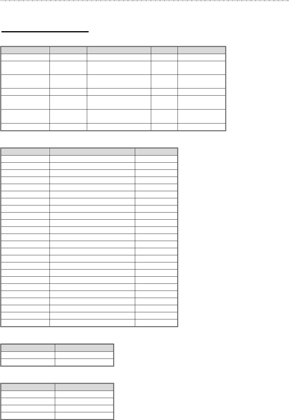
3.5 Pin Assignment
Table 3-1. Interface J3 Pin Assignment
DB9 Signal Direction PCB-J1 Signal
5 GND 1 GND
2 RxD
Å
Serial data to host 2 TXD1
3 TxD
Æ
Serial data from host 3 RXD1
4 VCC
Serial Pass-thru or
USB data 5 TXD2
(or USB D-)
Serial Pass-thru or
USB data 6 RxD2
(or USB D+)
Shield 7 Shield
Table 3-2. Extension Port J1 Pin Assignment
Pin Signal Comment
1 Extended IO
2 Extended IO
3 Extended IO
4 Extended IO
5 GND
6 VCC 5Vdc
7 Extended IO
8 Extended IO
9 Extended IO
10 Extended IO
11 Buzzer + output
12 Buzzer – output
13 Extended IO
14 Extended IO
15 Extended IO
16 Extended IO
17 Extended IO
18 Extended IO
19 Extended IO
20 Extended IO
21 Extended IO
22 Extended IO
23 Extended IO
24 Extended IO
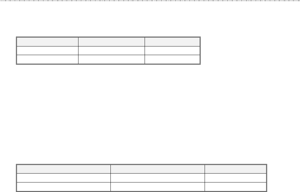
Table 3-3. 50 RF Antenna Port J2B Pin Assignment
Contact number Signal
1 RF output
2 GND
Table 3-4. Direct Match Antenna Port J2A Pin Assignment
Contact number Signal
1 RX
2 TX
3 GND
4 GND

UIC681 Programmer’s Manual UDN PM063-U Rev. 4
3-4
3.6 Communication
• RS232 Interface Data Output
Synchronization
The interface receives and transmits serial asynchronous data at voltage levels
compatible with the RS232 specification.
Baud Rate
9600 BPS default (optional: 1200/2400/4800/9600/19200/38400/56000/115.2K BPS)
• RS232 Interface Pass Through
Baud Rate
9600 BPS default (optional: 1200/2400/4800/9600/19200/38400 BPS)
• USB Interface
Compatible with USB specification 1.1
• F2F TTL Interface (Optional)
Each track has the clock and data. Please refer to command set for the detail setting.
• Transmission Protocol
The user may select from three different protocols: Protocol 0, 1, and 2.
Upon reset, the reader sends the power-on response “:”, depending upon the
configuration setting. The reader then configures itself to the protocol of the first
command from the host. From this point on, the protocol is unchangeable until a reset
occurs.
Protocol 0
In Protocol 0, all characters are transmitted and received using exactly the characters
listed in section 4. There are no headers and Block Check Characters (BCC). Protocol
0 presumes no transmission errors. If the host detects an error, it may request a
retransmission.
Table 3-5. Example for Protocol 0
Protocol 1
In Protocol 1, all messages are preceded by the ASCII character <STX> and
terminated with the ASCII character <ETX>, followed by a one byte <BCC>.
<BCC> is an XOR of the 7 data bits, excluding parity, of each character in the entire
message, including <STX>.
Format: <STX><MESSAGE><ETX><BCC>
Host Command Reader Response Comment
P Ready to read
^ Reader ACK
UIC681 Programmer’s Manual UDN PM063-U Rev. 4
3-5
where STX=02Hex and ETX=03Hex.
Table 3-6. Example for Protocol 1
Protocol 2
In Protocol 2, all messages are preceded by the ASCII character <SOH>, followed by a
one byte reader address, two bytes character count and terminated with a one byte
<BCC>.
The <BCC> is an XOR of the characters (8 bits) in the entire message, including
<SOH>.
Format: <SOH><ADDRESS><00Hex><COUNT><MESSAGE><BCC>
Table 3-7. Example for Protocol 2
The <ADDRESS> field is for a multi-reader system. This function is not currently
supported. The recommended value for this field is NULL (00Hex), however, any value
will work.
For Protocols 1 and 2, if the reader detects an error in an incoming transmission, it will
respond with a “Communications Error” message. If the host detects a transmission
error, it may request a retransmission. Besides, all protocols enforce a 10mSec timeout
between characters.
• Self – Arm Mode
The default reader configuration is the “Self-Arm Mode”, which allows the payment
cards (Including PayPass Magnetic Stripe, VISA MSD, ExpressPay card and the
general magnetic stripe credit cards) reading functions to run automatically, reporting
the card data to the host without instruction from the host.
In the Self-Arm Mode, the reader also can accept commands from host. However, the
reader can be configured to only “Host Polled Mode” by disabling Self-Arm Mode. The
“Host Polled Mode” allows the card reading functions to run by commands.
• Transmission Format
In Self-ARM mode, the default setting of card data output doesn’t include the protocol
envelope code. The user can turn on the envelope code by utilized the configuration
command – SE, TO. (Please refer to the appendix section of UIC681 Configuration
Guide)
Host Command Reader Response Comment
02h 50h 03h 51h Ready to read
02h 5Eh 03h 5Fh Reader ACK
Host Command Reader Response Comment
01h 00h 00h 01h 50h 50h Ready to read
01h 00h 00h 01h 5Eh 5Eh Reader ACK

UIC681 Programmer’s Manual UDN PM063-U Rev. 4
3-6
Card output format (Self-ARM mode)
Preamble Protocol
Envelope
code Tk1 prefix Tk1 Data Tk1 suffix
Separator Tk2 prefix Tk2 Data Tk2 suffix
Separator Tk3 prefix Tk3 Data Tk3 suffix Protocol
Envelope
code Postamble
The preamble/postamble is only available in the card data output format under
Self-ARM mode.
Read data for command (Host-Polled mode)
The reader replies the host command such as “Transmit Track Data” so called
“Host-Polled”. The requested message is encapsulated in the protocol envelope.
The response of Transmit Track Data command list as below:
Read tk1 data for command
Protocol
Envelope code Tk1 prefix Tk1 Data Tk1 suffix Protocol
Envelope
code
Read tk2 data for command
Protocol
Envelope code Tk2 prefix Tk2 Data Tk2 suffix Protocol
Envelope
code
Read tk3 data for command
Protocol
Envelope code Tk3 prefix Tk3 Data Tk3 suffix Protocol
Envelope
code
NOTE1: Tkx data: SS (option) track data ES (option) LRC (option)
NOTE2: Preamble/Postamble, prefix/suffix are optional based on reader’s configuration.
NOTE3: Protocol Envelope code can be <HEADERS>, <BCC> or NONE depended on
what protocol is in used.

UIC681 Programmer’s Manual UDN PM063-U Rev. 4
4-1
Section4: Commands and Responses
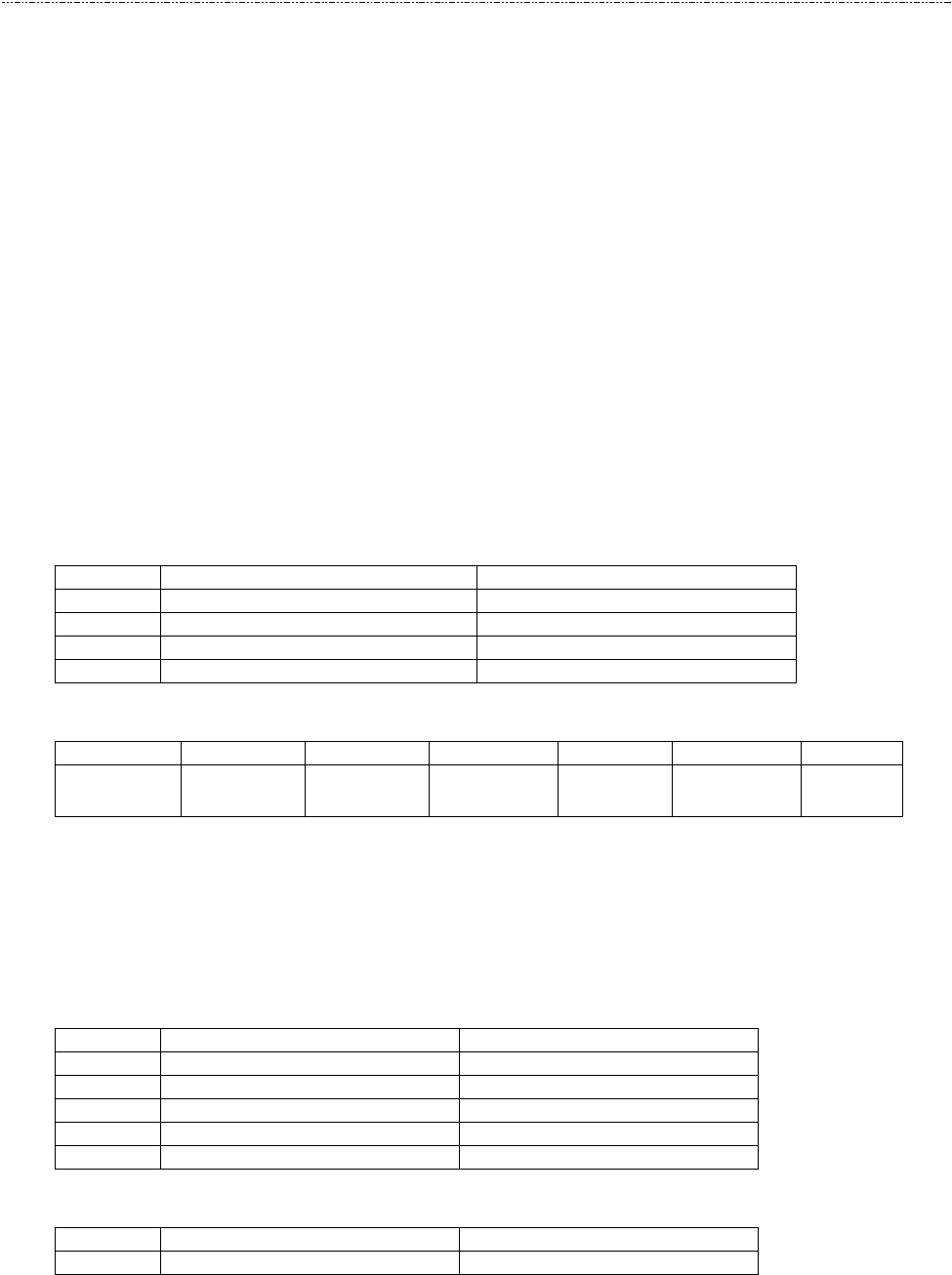
4.1 Reader Default Setting
Item Description EEPROM Default Value
Interface type RS232
UART1 setting (Txd1/Rxd1) 9600-8-N-1
Data pass through mode Disable
UART2 setting (Txd1/Rxd2) 9600-8-N-1
Buzzer Enable
Protocol format USI0
Contactless Self-ARM mode Enable
Contactless smart card manual type Type A
NOTE1: When “Contactless self-arm mode” turns on, UIC681 will automatic read the
payment card1 in the reading zone for both type A and B cards.
NOTE2: The contactless card operation commands are invalid when “Self-ARM mode” is
enabled. To switch manual operation mode, user needs to disable the “Self-ARM
mode” first.
1 Payment card – the card with PayPass, ExpressPay, or MSD application.

UIC681 Programmer’s Manual UDN PM063-U Rev. 4
4-2
4.2 Reader Command Description
• % (25H) – Retransmit
COMMENT Retransmits the last message sent by the reader.
NOTE Command is turned off in self-arm mode.
• 70 (3730H) or 90 (3930H) – Serial Number Report
COMMENT Transmit serial number information.
The serial number will be stored in the EEPROM and stored as an eight-digit ASCII
character array.
Example: “00000000”
• 71 (3731H) or 91 (3931H) – Copyright Report
COMMENT Transmit version and copyright information.
Send this when you want to know the version and copyright of the Model UIC681
firmware currently loaded. The response is an ASCII string giving the firmware date
(yymmdd), reader type and the firmware version number followed by the firmware
copyright statement. The firmware copyright statement is absent in OEM version.
Example: “60706,UIC 6800104C:V4.C”
• 72 (3732H) or 92 (3932H) – Reader Model Number Report
COMMENT Transmit reader model information.
The model number will be stored in the reader code area.
Example: “UIC681-RR”
• 73 (3733H) or 93 (3933H) – Reader PCB Number Report
COMMENT Transmit reader PCB number.
The PCB number will be stored in the EEPROM and stored as an eight-digit ASCII
character array.
Example: “680-REV1”

UIC681 Programmer’s Manual UDN PM063-U Rev. 4
4-3
• 77 (3737H) or 97 (3937H) – Reader Configuration Data Report
COMMENT Transmit the reader configuration data.
The data from the reader configuration area will be transmitted to the host as hex
values with the command “77” [offset] [num]. The reader will return any or all the bytes
from the reader configuration. The offset is an optional byte and the available value is
from 0x00 to 0x3F. The num is an optional byte specifying the number of configuration
bytes to be returned. If the offset and length bytes are omitted then the current
configuration starting at offset 0 is transmitted.
Example:
BE 4C 03 03 00 00 00 61 30 35 30 35 30 36 82 00
00 00 00 00 00 00 00 00 00 00 00 00 00 00 00 00
00 00 00 00 00 00 00 00 00 00 00 00 00 00 00 00
00 00 00 00 00 00 00 00 3A 36 38 30 2D 52 48 00
• 78 (3738H) or 98 (3938H) – Reader Customer Configuration Data Report
COMMENT Transmit the reader customer configuration data.
The data from the reader customer configuration area of the EEPROM will be
transmitted to the host as hex values with the command “78¨ [offset] [num]. The reader
will return any or all the bytes from the reader configuration. The offset is an optional
byte and the available value is from 0x00 to 0x3F. The num is an optional byte
specifying the number of configuration bytes to be returned. If the offset and length
bytes are omitted then the current configuration starting at offset 0 is transmitted.
Example:
00 30 30 30 30 30 30 30 30 36 38 30 2D 52 45 56
31 03 04 03 02 00 3C 00 80 00 00 00 00 00 00 00
00 00 00 00 00 00 00 45 00 2B FF FF FF FF FF FF
FF FF FF FF FF FF 3F 3F 12 FF 06 3F 05 13 50 03
• 79 (3739H) or 99 (3939H) – Reader Manufacturing Configuration Data Report
COMMENT Transmit the reader manufacturing configuration data.
The data from the reader manufacturing configuration area of the flash will be
transmitted to the host as hex values with the command “79” [offset] [num]. The reader
will return any or all the bytes from the reader configuration. The offset is an optional

UIC681 Programmer’s Manual UDN PM063-U Rev. 4
4-4
byte and the available value is from 0x00 to 0x7F. The num is an optional byte
specifying the number of configuration bytes to be returned to the host. If the offset and
length bytes are omitted then the current configuration starting at offset 0 is
transmitted.
Example:
BE 4C 03 03 00 00 00 61 30 35 30 35 30 36 82 00
00 00 00 00 00 00 00 00 00 00 00 00 00 00 00 00
00 00 00 00 00 00 00 00 00 00 00 00 00 00 00 00
00 00 00 00 00 00 00 00 3A 36 38 30 2D 52 48 00
• 9 (39H) – Version Report
COMMENT Transmit version information.
Send this when you want to know the version of UIC681 firmware currently loaded.
The response is an ASCII string giving the firmware date (mmddyy), reader type and
firmware version number.
Example: “060706,UIC681-RR:V4.C¨.
• ? (3FH) – Select Verbose Responses Command
COMMENT Most error responses until the reader receives a reset command
will include a short descriptive message.
• $ (24H) – Reader Status Request
COMMENT Interrogate the reader about its operational status. Two bytes of status
information will be returned.
First Status Byte
Bit Value: 0 Value: 1
0 – 4 Reserve for future use Reserve for future use
5 No Magnetic Stripe Card data Magnetic Stripe Card data
6 Not armed to read Armed to read
7 Reserve for future use Reserve for future use
Second Status Byte (reserve for future use)
UIC681 Programmer’s Manual UDN PM063-U Rev. 4
4-5
• L (4CH) – LED ON
• l (6CH) – LED OFF
• ( (28H) – LED Flash
COMMENT 1.Turn first/second LED ON/OFF/Flash, as specified.
2.Transmits an acknowledgement "^" (5EH).
NOTE 1.These commands are disabled in the self-arm mode.
2.These commands only use in LED model.
• # (23H) – Configuration Request
COMMENT Return standard one byte or extended 16-byte string with configuration.
NOTE Using the configuration setting command to select standard or extended
format.
Standard One Configuration Byte
Bit Value: 0 Value: 1
0 Track 1 not present Track 1 present
1 Track 2 not present Track 2 present
2 Track 3 not present Track 3 present
3-7 Reserved for future use Reserved for future use
Extended Configuration Bytes (16 bytes)
Byte 0 1 2 3 4 5-15
Remark Equip.0 Equip.1 Protocol Speed Address Reserved
Protocol: 0=USI0; 1=USI1; 2=USI2.
Speed: 0=1200, 1=2400, 2=4800, 3=9600, 4=19.2k, 5=38.4k, 6=56k, and 7=115.2k
bps.
Address: Always 00H.
Equip. 0 - Extended Configuration Byte 0
Bit Value: 0 Value: 1
0-3 Reserved for future use Reserved for future use
4 Track 1 not present Track 1 present
5 Track 2 not present Track 2 present
6 Track 3 not present Track 3 present
7 Reserved for future use. Reserved for future use
Equip. 1 - Extended Configuration Byte 1
Bit Value: 0 Value: 1
0 - 7 Reserved for future use Reserved for future use

UIC681 Programmer’s Manual UDN PM063-U Rev. 4
4-6
• <DC2> (12H) – RS232 pass through enable
COMMENT Enable RS232 data Pass Through (PT) function temporarily.
FORMAT The command characters are followed by an ASCII ‘P’ to enable the
RS232 pass through function. It is only valid in RS232 model.
NOTE Once the pass through mode is enabled, UIC681 passes all data
between COM1 and COM2 and do nothing. Power cycling (if the default
of PT is disable) or send the string “<DC2>P<DC2>a<DC2>s<DC2>S”
brings UIC681 back to normal operation. Before sending this command,
the user must assure the PT function is desired.
• <CAN> (18H) – Clear Data Buffer
COMMENT Clear the card data buffer.
• <7FH> – Warm Reset
COMMENT Abort all current actions and cause the device to execute all initialization
functions. The device will respond as it would for a "power up" cycle, but
always returning a “:” (3AH). This operation will take at least 3 seconds.
• <09H> – Configuration Setting
COMMENT This command is used to set configuration in EEPROM.
FORMAT The command (09H) is followed by the configuration data format to set
the configuration in EEPROM. Please see “UIC681 Configuration Guide”
for more details.
• P (50H) – Arm to Read
COMMENT 1.Clear read data buffers.
2.Transmit command acknowledgement (“^” 5EH).
3.Wait for card approached.
4.Transmit read acknowledgement ("^") after card read.
After an "Arm to Read" command is received and acknowledged the only
commands that will be accepted for execution are: <ESC> (Abort), ”$”
(Status), LED control commands and Reset command.
In self-arm mode, it is not necessary to send this command, if sent it will
temporarily override self-arm mode.

UIC681 Programmer’s Manual UDN PM063-U Rev. 4
4-7
• p (70H) – Arm to Read (Used for Manufacturing Test Only)
COMMENT 1.Clear read data buffers.
2.Transmit command acknowledgement (“^” 5EH).
3.Wait for card read.
4.If the card media is detected a "(" (28H) byte is sent, when
media detect goes inactive a “)” (29H) byte is sent.
This is similar to the 'P' command but send ‘(‘ at start of magnetic stripe
card data and ‘)’ at end.
• <ESC> (1BH) – Abort Arm to Read
COMMENT 1.Clear read data buffers.
2.Abort Arm to Read Command.
3.Transmit command acknowledge (“^” 5EH).
• Q (51H) – Transmit Track 1 data
• R (52H) – Transmit Track 2 data
• S (53H) – Transmit Track 3 data
COMMENT 1.Detect the card type automatically and process data in the read buffer.
2.If error is detected, transmit proper error response ('*' or '+'),
refer to “Responses to the Host” section.
3.Else, transmit data in ASCII.
• H (48H) – Self-ARM function disable/enable
COMMENT Disable auto read function temporarily if Self-Arm is enabling.
H [Enable/Disable, 1 byte]
[Enable/Disable]
0 (30h, ASCII Hex) - Self-Arm disable
1 (31h, ASCII Hex) - Self-Arm enable
NOTE UIC681 cannot perform the Self-ARM enable command for the contactless
payment card reading under below conditions:
1.The payment card is decoded successful and the UIC681 is waiting the
card to be removed from the reading zone.
2.The payment card is failed to decode and the UIC681 is waiting the card
to be removed from the reading zone.

UIC681 Programmer’s Manual UDN PM063-U Rev. 4
4-8
RESPONSE ‘^’ – Acknowledgement
‘*’ – Cannot execute
‘!’ – Bad parameter

UIC681 Programmer’s Manual UDN PM063-U Rev. 4
4-9
4.3 Contactless Card Operation Command Description
• G (47H) – ISO14443 type protocol select
COMMENT Select ISO 14443 type A or B which manual command operated.
G[Type, 1 byte]
[Type]
0 (30h, ASCII Hex) - ISO14443 A
4 (30h, ASCII Hex) - ISO14443 B
The default contactless smart card type is type A after power up.
RESPONSE ‘^’ – Acknowledgement
‘!’ – Bad parameter
• O (4FH) – Antenna power ON
COMMENT Apply power on the antenna. This command is for manual command
operation.
RESPONSE ‘^’ – Acknowledgement
‘*’ – Failed, the reader is in Self-Arm mode. The antenna power cannot
be turned off.
• o (6FH) – Antenna power OFF
COMMENT Turn the antenna power off.
RESPONSE ‘^’ – Acknowledgement
‘*’ – Failed, the reader is in Self-Arm mode. The antenna power cannot
be turned off.
• b (62H) – Request
COMMENT Request command.
b[Req command, 1 byte] - If reader is set to ISO14443 type A
[Req command] (optional)

UIC681 Programmer’s Manual UDN PM063-U Rev. 4
4-10
The request command code is ISO14443 type A. It can be either 26 (REQA) or 52
(WUPA)
NOTE If the [Req command] field does not appear in the request command, reader
will set the request mode to WUPA automatically.
b[AFI, 1 byte][Parameter, 1 byte] - If reader is set to ISO14443 type B
[AFI](optional) - Binary hex (00h to FFh), please refer to ISO 14443-3 for the detailed
information
[Parameter](optional) - Binary hex (00h to FFh), please refer to 14443 for the detailed
information.
NOTE If the [AFI] and [Parameter] do not appear in the request command, reader
will set the request mode to WUPB automatically.
RESPONSE ATQA (2 bytes, type A, Binary Hex) or ATQB (16 bytes, type B, Binary
Hex) if command executed successfully
‘*’ – No card response or No power on the antenna
• c (63H) – Anticollision(type A)/Slot-Marker(type B)
COMMENT In type A mode, the reader sends the Anti-collision command to the card.
In type B mode, the reader sends the Slot-Marker command to the card.
c – ISO 14443 type A
c[APn] – ISO14443 type B
[APn] – Anti-collision prefix byte.(type B only)
NOTE Slot-Marker is not a mandatory command for type B card.
RESPONSE If the command executed successfully, the reader returns
PICC serial number for type A (Binary Hex)
or
PICC send ATQB (12 bytes, Binary Hex) for type B
‘*’ – No card response or or No power on the antenna
‘!’ – Bad parameter
• f (66H) – Select(type A)/Attrib(type B)
COMMENT In type A mode, the reader sends the SELECT command to the card.
In type B mode, the reader sends the ATTRIB command to the card.

UIC681 Programmer’s Manual UDN PM063-U Rev. 4
4-11
RESPONSE If the command executed successfully, the reader returns
‘^’ + SAK( 1 byte)
or
‘^’ + MBLI/CID(1 byte)
‘*’ – No card response or No power on the antenna
• g (67H) – Mifare classical card authentication (Support Mifare classical card only)
COMMENT Mifare classical card authentication.
g[Block number, 3 bytes][Key number, 1 byte][Key type]
Authenticate the card with the key stored in EEPROM.
or
g[Block number, 3 bytes] ][Key type] [Key, 12 bytes]
Authenticate the card with the key in [key field].
[Block number]
There are two types of block format
000 to 255 (30h30h30h to 32h35h35h, ASCII Hex)
or
B<00><00> to B<00><FF> (42h00h00h to 42h00hFFh, ASCII Hex)
[Key number]
0 to 4 (30h to 35h, ASCII Hex)
[Key]
0 to 9 or A to F (30h - 39h or 41h - 46h, ASCII Hex)
[Key type]
A or B (41h or 42h)
RESPONSE ‘^’ – acknowledgement
‘*’ – No card response or No power on the antenna
• h (68H) – Mifare classical card read block (Support Mifare classical card only)
COMMENT Mifare classical card read command.
h[Block number, 3 bytes]

UIC681 Programmer’s Manual UDN PM063-U Rev. 4
4-12
[Block number]
There are two types of block format
000 to 255 (30h30h30h to 32h35h35h, ASCII Hex)
or
B<00><00> to B<00><FF> (42h00h00h to 42h00hFFh, ASCII Hex)
RESPONSE block data (16 bytes, Binary Hex) if command executed successfully
‘*’ – No card response or No power on the antenna
• i (69H) – Mifare classical card write block (Support Mifare classical card only)
COMMENT Mifare classical card write command.
i[Block number, 3 bytes][Block data, 4 bytes or 16 bytes]
[Block number]
There are three types of block number format
000 to 255 (30h30h30h to 32h35h35h, ASCII Hex) General Mifare Block
or
B<00><00> to B<00><FF> (42h00h00h to 42h00hFFh, ASCII Hex) General Mifare
Block
or
U<00><00> to B<00><FF> (55h00h00h to 42h00hFFh, ASCII Hex)
Mifare Ultralight
[Block data]
For Mifare Ultralight, the block data should be 4 bytes, others are using 16 bytes block
data.
RESPONSE ‘^’ – Acknowledgement
‘*’ – No card response or No power on the antenna
• t (74H) – Mifare Value Operation (Support Mifare classical card only)
COMMENT Mifare classical card value operation command.
t[Block number, 3 bytes][Operation mode, 1 byte][Value, 4 bytes][transfer block, 3
bytes]

UIC681 Programmer’s Manual UDN PM063-U Rev. 4
4-13
[Block number]
There are two types of block number format
000 to 255 (30h30h30h to 32h35h35h, ASCII Hex)
or
B<00><00> to B<00><FF> (42h00h00h to 42h00hFFh, ASCII Hex)
[Operation mode]
0 (30h, ASCII Hex) – Decrement
1 (31h, ASCII Hex) – Increment
2 (32h, ASCII Hex) – Restore
3 (33h, ASCII Hex) – Decrement and transfer to the different block.
4 (34h, ASCII Hex) – Create Mifare Value in the block.
[Value]
Binary Hex from 0h to FFh
For option 3 only, the data format is same as [block number]
RESPONSE ‘^’ – Acknowledgement
‘*’ – No card response or No power on the antenna
‘!’ – Bad parameter
• X (58H) – Mifare classical card activation
COMMENT Perform request/anticollision/select command to activate the card.
It is also can be used for any ISO14443 compatible card.
RESPONSE ATQA/SAK/serial number if the command executed successfully for type
A card
ATQB (12 bytes) if the command executed successfully for type B card
‘*’ – No card response or No power on the antenna
• x (78H) – Card halt
COMMENT Card halt command.
RESPONSE ‘^’ – acknowledgement
‘*’ – No card response or No power on the antenna

UIC681 Programmer’s Manual UDN PM063-U Rev. 4
4-14
• J (4AH) – Activate PICC cpu card
COMMENT Activate PICC cpu card command. The Antenna POWER ON command
has to be sent first.
RESPONSE ATS (type A) or PUPI (type B) if command executed successfully
‘*’ – No card response or No power on the antenna
• j (6AH) – Load Mifare key (Support Mifare classical card only)
COMMENT Save up to 5 key sets for Mifare classical card application
NOTE For security reason, there is no way to retrieve the key back.
j[Key number, 1 byte][Key data, 12 bytes]
[Key number]
0 to 4 (30h to 39h, ASCII Hex)
[Key data]
0 to 9 or A to F (30h - 39h or 41h - 46h, ASCII Hex)
RESPONSE ‘^’ – acknowledgement
‘*’ – No card response or No power on the antenna
• y (79H) – Send DESELECT command
COMMENT Send ISO14443 layer 4 DESELECT command to card
RESPONSE ‘^’ – acknowledgement
‘*’ – No card response or No power on the antenna
• Z (5AH) – I/O to contactless CPU card with APDU format
COMMENT The command is used to pass an APDU to the card where both data and
an ISO status are expected in the response.
Z[APDU, variant, 262 bytes max]
[APDU] Binary hex (00h to FFh)
If successful, the data from the ICC and the two byte SW1/SW2 ISO 7816-4 response
are returned.
UIC681 Programmer’s Manual UDN PM063-U Rev. 4
4-15
If unsuccessful, reader transmits '*'.
APDU Command Structure
CLA INS P1 P2 P3
Lc or Le Data
(If Lc present)
APDU Response Structure
Data (optional) SW1 SW2
• z (7AH) – I/O to contactless card for block data exchange
COMMENT The command is used to pass a block data to a card.
z[CRC mode, 1 bytes][Wait time, 4 bytes][Block data, 384 bytes max.]
[CRC mode]
0 (30h, ASCII Hex) – Block data contain 2 bytes CRC and enable CRC transmission.
1 (31h, ASCII Hex) – No CRC in block data and disable CRC transmission.
[Wait time]
0000 to 9999 (30h30h30h30h to 39h39h39h39h, ASCII Hex) Waiting time in ms.
[Block data]
Binary hex (00h to FFh), Maximum accepts 384 bytes.
If successful, the data from the ICC are returned.
If unsuccessful, reader transmits '*'.

UIC681 Programmer’s Manual UDN PM063-U Rev. 4
4-16
4.4 Responses to the Host
^ (5EH) Acknowledge. Acknowledges correct completion of most recent command.
* (2AH) Command was received correctly. But could not be completed.
+ (2BH) No Magnetic Stripe Card Data. Command was received correctly.
? (3FH) Communication Error. Command was not received correctly.
! (21H) Invalid Command or bad parameter.
: (3AH) Power On report.
~ (7Eh) Unavailable. Hardware not available to complete this request.

UIC681 Programmer’s Manual UDN PM063-U Rev. 4
5-1
Section5: Application Example
The default setting of UIC681 reader, Self-ARM mode, is mainly to simplify the process
for the host that doesn’t need to communicate to each other. In this situation, the UIC681
acts like a general magnetic stripe card reader whenever it senses the card, it will try to
decode the card data automatically and send the decoded data to the host if the process is
successful. Otherwise, no information is sent out.
If the application would like to take whole control on the reader, it is recommended
using the “Host Polled” mode instead of the “Self-ARM” mode. It can be done by either
sending “Self-ARM” disable command or changing default setting in the reader
configuration.
Once UIC681 receives the Self-ARM disable command, H0 (see the command
description section), it turns off auto-read function and waits for the “Arm-to-Read”
command, P, for next transaction. Since the Self-ARM disable command won’t change the
EEPROM setting, UIC681 will turn back to Self-ARM for next power cycling. Besides, the
Self-ARM enable command, H1, can also bring UIC681 back to Self-ARM.
To disable Self-ARM mode permanently, the host needs to set the EEPROM value of
UIC681. The configuration command SAx (x = E or D, see the Configuration Guide) saves
the setting into the EEPROM of UIC681 and keep the value until next changed.
Meanwhile, it is recommended using the Protocol 2 (USI2) for “host polled” application
because USI2 contains the header, message counter and block check character. It is better
than Protocol 0 (USI0) and Protocol 1 (USI1) to prevent the data to be misinterpreted but
needs more redundant bytes.
UIC681 Programmer’s Manual UDN PM063-U Rev. 4
5-2
Host Polled Application Example
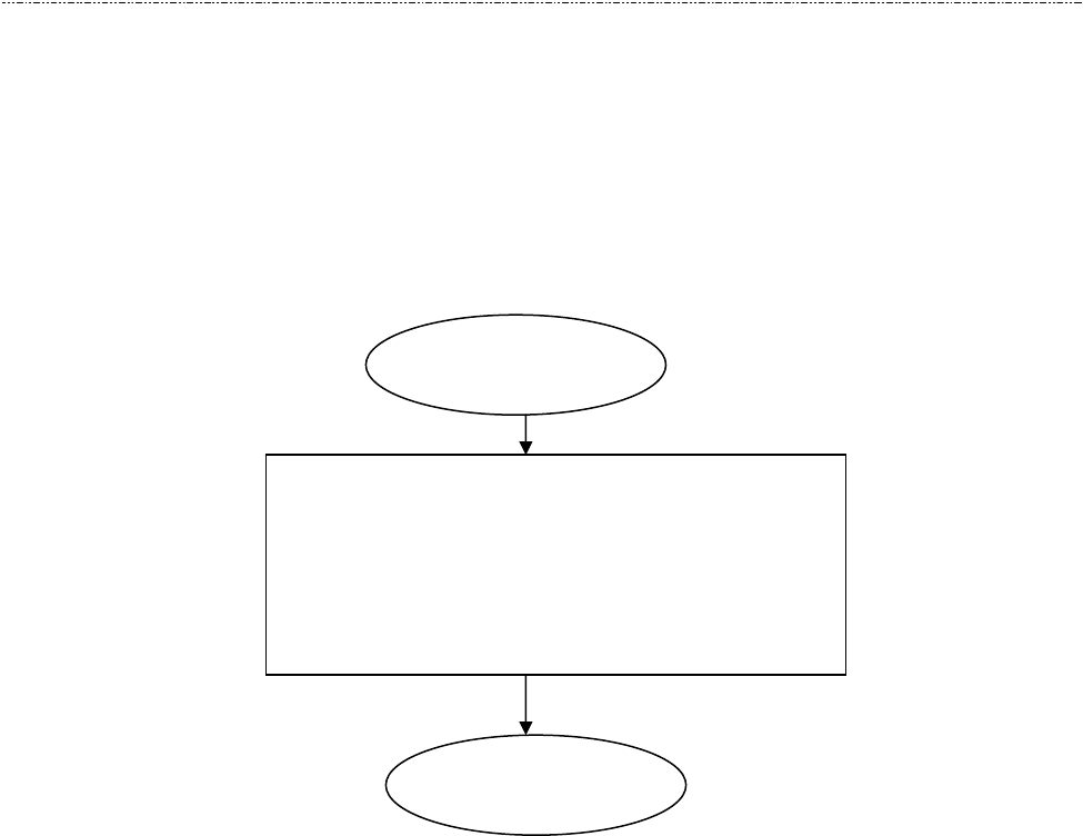
A. UIC681 setting changed
In this example, it assumes UIC681 is in factory default and the user would like to change it
to protocol USI2 and Self-ARM disable.
This process should be done only once to set the UIC681 to the proper state.
Due to the EEPROM life limitation, it is recommended that don’t change the
EEPROM value very frequently. Normally, the configuration setting has done in the
factory production stage, please contact UIC Sales representative for more detail
information.
Initial State
1. Send the configuration command to set
UIC681 to protocol 2.
2. Send the configuration command to set
UIC681 to Self-ARM disable.
Done
UIC681 Programmer’s Manual UDN PM063-U Rev. 4
5-3
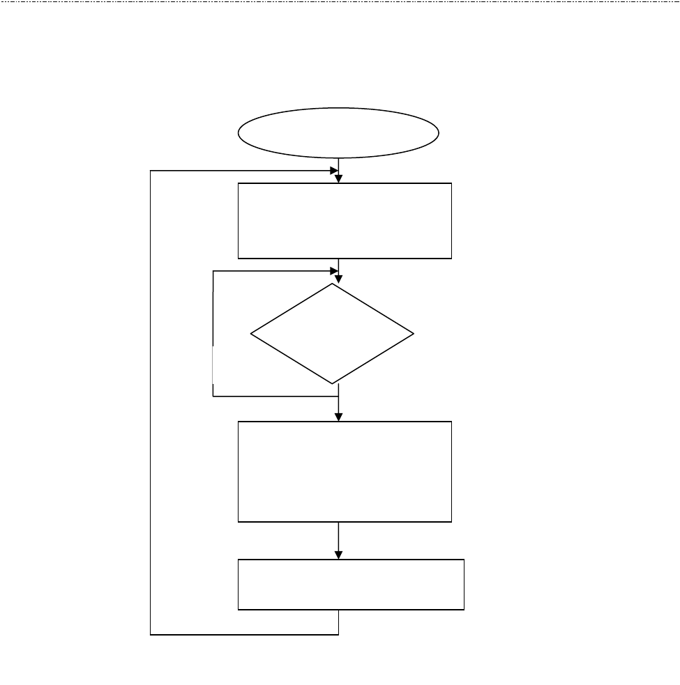
B. Operation Example
In this example, it assumes UIC681 is in protocol USI2 and Self-ARM disable.
After host issues the Arm-to-Read command, UIC681 will check if any payment card in the
reading read zone or any magnetic stripe card swiped (the magnetic stripe reader is
optional device). No matter the card is decoded succeed or failed, it will return ‘^’ to indicate
the card has been read. The host can issue Q, R, S command to retrieve the card data.
Read Card Start
Send “Arm-to-Read”
command to UIC681
Any card
read?
Send Transmit track 1, 2,
or 3 command to retrieve
track data
Card data processing
Yes
No
For next transaction