Uniform UIC802RFMG-001 Portable RFID and Magnetic Card Reader User Manual UIC802 Operation Manual 1 0
Uniform Industrial Corp. Portable RFID and Magnetic Card Reader UIC802 Operation Manual 1 0
Uniform >
Users Manual
1 of 15
UIC802 Portable Reader
Product User Guide
UDN UIC802-PUG Rev. 1.0
July-21-2005
Uniform Industrial Corp. (UIC)
47709 Fremont Blvd., Fremont, CA94538. U.S.A.
Tel: 510-438-6799 Fax: 510-438-6790 Toll Free: 1-888-881-1900
Email: info@uicusa.com URL: www.uicusa.com

2 of 15
What is the UIC802?
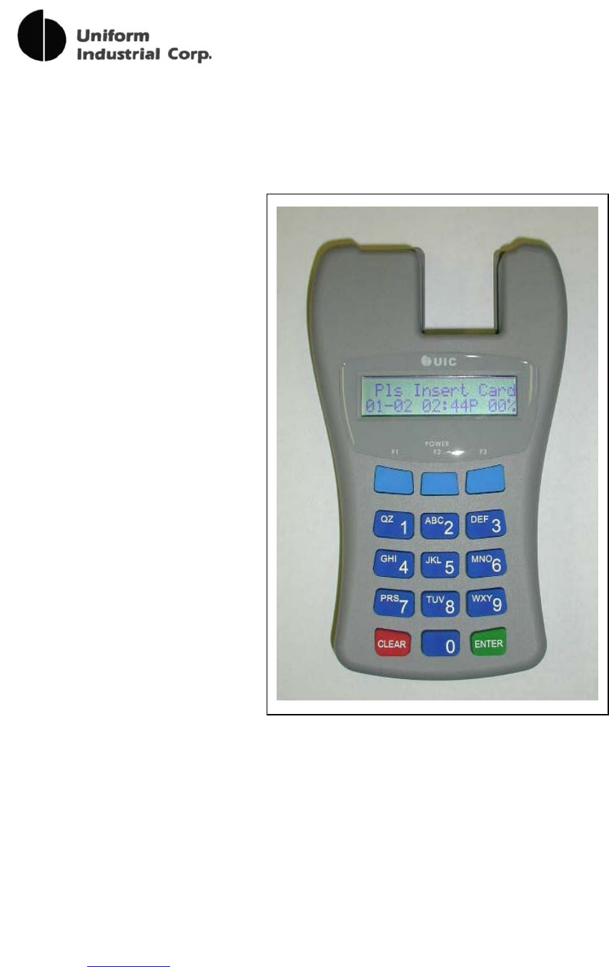
The UIC802 is a battery operated contactless RFID and magnetic stripe card reader designed
for data collection application such as Trade Show Lead Capture, Time & Attendance, Off-line
E-Payment, etc. The UIC802 has many advanced features yet it’s very simple to use.
The UIC802 contains two readers modules. One is the contactless RFID reader. The other
one is a manual insert magnetic card reader which can decode 3 tracks ISO, AAMVA, and
custom data formats. Each read data is stored into the internal 1 Mega byte flash memory. In
additional to the card data, the time and date, record number, ID entry, action code entry are
also being captured.
UIC802 Components
The UIC802 kit consists of the following components:
- The UIC802 Potable reader.
- The P.C. data upload cable.
- The UIC801 Utility Program diskette.
UIC802 Features
Magnetic Card Reader
- Support 3 tracks data decoding
- Reliable manual insert type
- 1 Mega byte flash memory for data capture
- Stores up to 4,000 card data
- Fully programmable, support track prefix, suffix,
separator codes programming
3 of 15
Portable Terminal for Data Collecting Applications
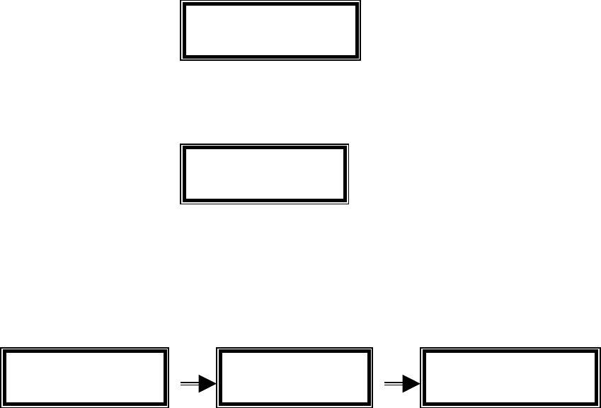
- Easy to read 2 lines x 16 characters LCD display
- Telephone style keypad for easy data entry and
reader setup
- Battery operated with low battery warning
- Real Time Clock
- Data can be imported to any spread sheet program
Advanced Electronics and Software
- 16-bit RISC processor plus RFID and Magnetic
Reader ICs
- 2 Serial I/O ports (1-RS232, 1-TTL) for P.C. data
upload, Printer, Bar-Code Scanner, etc
- Easy to use Window based Utility Program for data
upload, reader programming, and configuration
Build-in User and System Configuration Menu
- Reader can be setup easily to fit different data
collection applications
- Password protected System Menu entry for added
security
- Reader functionality can be changed in seconds
using the User Command Menu
Contactless RFID Card Reader
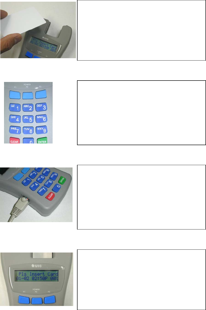
- Supports a reading distance of 1 inch
- Supports 13.560 MHz Type A / Type B cards
- 1 Mega byte flash memory for data capture
- Stores up to 4,000 card data
4 of 15
UIC802 Card Reading Operation
The UIC802 is designed specifically for data collection purpose. The LCD display prompt and
setup screens that make the UIC802 very easy to use. Here are some simple steps to operate
the UIC802. They involve the reading of two types of cards:
(I) Magnetic Card Only – when RFID is disabled
(II) Magnetic Card and RFID Card – When RFID is enabled
To learn how to turn on the RFID operation, please refer to the section of ‘RFID Enable’ in the
System Command Menu section.
(I) Magnetic Card Only Operation:
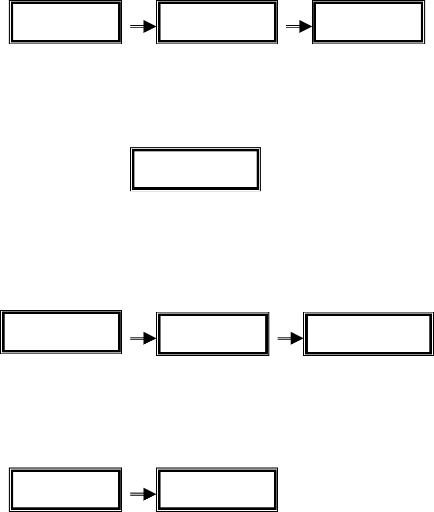
1. Press the POWER key to wake up the UIC802. The UIC802 will beep and displays the
idle prompt:
2. Insert the magnetic card all the way into the UIC802. It is very important not to
remove the card until “Pull Crd to Read” displays on the UIC802 LCD:
3. Remove magnetic card swiftly. The UIC802 display the first 32 bytes of the card data
and the message “Saving Data Now Be Patient” briefly. At this point, the card data
has been stored in the internal Flash memory. The display goes back to the idle
prompt.
4. If the UIC802 is unable to read the magnetic card due to bad card or improper swipe
speed. Two possible scenarios may occur.
a. The UIC802 is unable to detect any card data (for example, magnetic stripe is
reversed). The reader will beep 3 times to remind the user about this.
Pls Insert Card
08-15 12:36 P 00%
Pull Crd to Read
08-15 12:36 P 00%
TRACK111110123
4567890123456789
Saving Data Now
Be Patient
Pls Insert Card
08-15 12:37 PM 00%
5 of 15
b. The UIC802 detect read error. The UIC802 will display the error code and the
message “Pls Reinsert Card” as the idle prompt.
(II) Magnetic Card and RFID Card Operation
1. Press the POWER key to wake up the UIC802. The UIC802 will beep and displays
the idle prompt:
2. Read the RFID card by taping it against the upper left corner of the reader, where the
RFID antenna locates. The UIC802 will beep once, display the first 32 bytes of the
card data and the message “Saving Data Now Be Patient” briefly. At this point, the
card data has been stored in the internal Flash memory. The display will go back to
the idle prompt.
3. If the card is brought to a distance too far from the antenna and not detected by it, it
will have no response at all. The user has to bring it closer. If it is close enough, the
reader will read the card. However, if the card is bad or reading unsuccessful, it will
beep twice and show the following messages:
4. For this mode of dual card types operation, the user can always read the magnetic card
by inserting it into the slot. The responses will be the same as in the magnetic card only
case, except that the prompts messages are slightly different, to reflect either type of
card reading:
The “Pls Insert Card” will become “Please Read Card”. The “Pls ReInsert
Magnetic Error
Track 1
Pls Reinsert CRD
08-15 12:36 PM
Pls Insert Card
08-15 12:36 PM
Please Read Card
08-15 12:36 P 00%
WILLIAM SMITH 23
4567890123456789 Saving Data Now
Be Patient
Please Read Card
08-15 12:37 PM 00%
RFID
Bad Readin
g
Pls ReRead Card
08-15 12:36 PM

6 of 15
CRD” will become “ Pls ReRead Card”.
Function Keys F1 F2 F3
These function keys are used to scroll through the card content, after a card reading
was taken, no matter from the magnetic or contactless card. After a successful card
reading, pressing the CLEAR key and the F2 key together will bring the unit into card
data display mode. It will display the first 32 bytes of the card data. The pressing of
the F3 key, and so on, will display the next 32 bytes of the card data, or stay in the last
32 or less bytes of data, if it already comes to the end of the data buffer. Pressing the
F1 key, and so on, will bring back to the previous 32 bytes of the card data, or stay in
the first 32 bytes of data buffer, if it is already displaying the beginning of the data
buffer. Pressing the CLEAR key will leave this card data display mode and go back to
the idle prompt.
Please note that the F2 key and the POWER key are physically the same key. The
POWER key is pressed for waking up the unit when the latter is in sleeping mode.
While pressing the CLEAR key and the F2 key will display the card data of the last
card reading, when the reader is in the active operating mode.
UIC802 User Command Menu
The UIC802 can be used in many data collection applications such as Trade Show Lead
Capture, Time & Attendance, Off-line E-Payment, Inventory Control, etc. A User Command
Menu is implemented in the UIC802 for different configurations to be used in various
applications.
1. To access the User Command Menu, press the keys “CLEAR” and “6” together. The
LCD displays the message “USER COMMAND” briefly and then the User Setup
Selection menu, press “CLEAR” key to exit from User Command Menu anytime.
2. Selection “1” – I.D. Entry Option Enable
USER COMMAND 1=I 2=A 3=D 4=B
5=DT 6=PC 7=PR
PID Enable
1 = YES 2 = NO

7 of 15
When the I.D. Entry option is enabled, the UIC802 will prompt the user to enter the
PID (Personal Identification) number after a successful card read. The PID is any 6
digits number. The PID will be stored in Flash memory along with the captured card
data.
Application Example: Trade Show Lead Capture
This option can record which the sales person that took the lead. The sales person
ID will be stored in the memory with the captured lead information.
3. Selection “2” – Action Code Option Entry Enable
When the Action Code option is enabled, the UIC802 will prompt the user to enter the
Action Code after a successful card reading. The Action Codes are any 2 digits
numbers. Up to 5 Action Codes can be entered for each record. The Action Codes
will be stored in Flash memory along with the captured card data.
Application Example: Time & Attendance
This option can be used to indicate the time event such as Time In, Time Out, Lunch
Out, Lunch In, etc. These time events are pre-defined by the 2 digits code.
4. Selection “3” – LCD Display Option
1=Date Display date (MM-DD) at the idle prompt
2=Rec# Display total Record Number at the idle prompt
5. Selection “4” – Beeper Enable
1=YES Enable the beeper
2=NO Disable the beeper
Action Code EN
1 = YES 2 = NO
Display Mode
1=Date 2=Rec#
Enable Beep?
1=YES 2=NO

8 of 15
The UIC802 has build in buzzer to provide audio feedback for prompt to remove
card, card read error, request key entry from user, and completion of data saving
6. Selection “5” – Data Memory Access and Information
1=Upload To upload the content of the memory to P.C.
2=Rec# Display the total number of records (each card read)
3=% MEM Used Display the percentage of memory that are used
7. Selection “6” – Printer Output Option
1=DT Captured data send to RS232 port after each card swipe,
Print delay between records for impact printers
2=TH Captured data send to RS232 port after each card swipe,
Print delay between records for thermal printers
3=NO No data send out to RS232 port after each card swipe
8. Selection “7” – Print Record Option
1=ALL Print all the card data records stored in the flash memory
2=UNPRN Just print out the card data records that were not printed out
Before
UIC802 System Command Menu
The System Command Menu is used to set up the UIC802 configurations – Time and Date
setting, Sleep Timer, Change Unit Password, Erase flash memory, Set unit ID number, update
flash memory parameters and enable/disable the RFID operation.
1=Upload 2=Rec#
3=% MEM Used
Printer Connect
1=DT 2=TH 3=NO
Print Record
1=ALL 2=UNPRN
9 of 15
1. To access the System Command Menu, press the keys “CLEAR” and “9” together. The
System Command Menu is password protected. The LCD displays the message “Enter
Password”. ( Default password is 842811 ). Press “CLEAR” to exit from the System
Command Menu anytime.
Key in the 6 digits password and the “ENTER” key. The LCD displays the System Command
selection menu
2. Selection “1” – Time and Date setting. The LCD displays the message “Enter
Date” briefly and then the time and date setup screen.
Key in the month, day, year, hour, minute, second and press “ENTER”.
3. Selection “2” – Sleep Timer, the automatic shutdown feature is incorporate for battery
power savings. The UIC802 will shut off after a period of no activity. This period time can
be selected from this menu. “1” equal to 30 seconds, “2” equal to 60 seconds, “3” equal
to 180 seconds and “4” will disable the auto off feature.
4. Selection “3” – Enter New Password, the default password can be changed to any 6
digits number.
Enter Password
Enter Date
08-15 10:28 PM
Sleep Timer 1=30
2=60 3=180 4=NO
Ent New Password
1=DT 2=SP 3=PW
4ER 5ID 6UF 7RF
mmddyyyy hhmmss

10 of 15
5. Selection “4” – Erase Data, this menu selection is used to erase all data from flash
memory and reset all setting back to the factory default. Please use this selection with
care. The data cannot be recovered once the flash memory is erased.
1=YES Erase all data from flash memory.
2=NO Exit from this menu selection
3=RS*
Reset all settings back to the factory default setting
*Warning: All user setups will be erase from memory, need to re-enter all user
settings, such as New Password, User ID#, user options, etc.
6. Selection “5” – Enter Unit I.D. number, the unit ID# is any 6 digit number. The unit I.D.
number will be sent along each data record
7. Selection “6” – Update FlashMEM, the unit configuration settings as programmed in
“User Command Menu”, “System Command Menu”, and Printer Translation Table are
normally save in RAM. The setting can be lost if the battery power is completely drained.
The “Update FlashMEM” selection will copy these setting to Flash Memory for permanent
storage.
8. Selection “7” – RFID Enable
1=YES Turn ON the RFID circuit and starts to process for RFID
request
2=NO Turn OFF the RFID circuit
Unlike the magnetic card reader which is always enabled, normally the RFID circuit
Erase Data
1=YES 2=NO
3=RS
Enter Unit ID#
Update FlashMEM
1=YES 2=NO
Turn ON RFID
1=YES 2=NO
11 of 15
of the reader is turned off in order to reduce the power consumption. However, if we
have to read RFID cards, we have to turn on the circuit through this command
menu.
UIC801 Utility Program
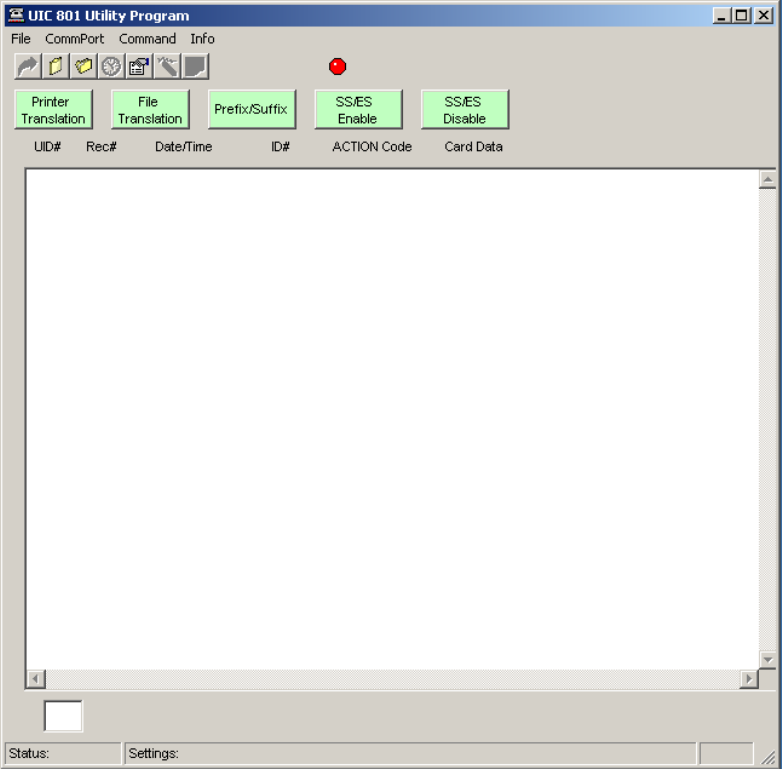
The UIC801 Utility Program greatly simplifies and enhances the usage of the UIC802 Portable
Reader. The UIC801 Utility Program has the following functionality.
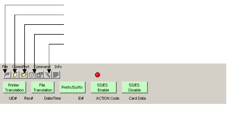
1. Upload Data – retrieve data from the UIC802 reader flash memory to the Utility
Program buffer. Depend on the record size, this operation may take a few minutes.
The small window on the lower left hand corner displays the data transfer activities.
2. Display Data – display retrieved data on the UIC801 Utility Program window. Activate this
function after the Upload Data transfer is completed.
3. Save Data to File – save the retrieved data to a file for export to any spreadsheet or
unique application software program.
4. Auto Time Set – automatically set/synchronize the time of the UIC802 reader with the
P.C.
5. Erase Memory – erase the flash memory of the UIC802 reader.
6. Printer Translation – translate any character in the card data into printer control command
character string, up to 16 2-digit hex numbers.
7. File Translation – translate any character in the card data into special control character
string, up to 16 2-digit hex numbers.
8. Track Prefix/Suffix – program track prefix, suffix, and field separator codes to the UIC802
reader.
9. ES & SS Enable – enable tracks SS (Start Sentinel) and ES (End Sentinel)
10. ES & SS Disable – disable track SS (Start Sentinel) and ES (End Sentinel)
12 of 15
Utility Program Installation
1. Copy the contents of the UIC801 Utility Disk to a newly created folder in the local hard
drive.
2. Open the folder and click the program “UIC Utility”.
3. Connect the UIC801 to the RS232 COM 1 port of the P.C. Make sure the UIC802 is
power on. We recommend setting the sleep timer option to 2 = 300 second.
4. Click the red indicator located above “SS/ES Enable”. The red indicator should change
to green color. The UIC801 Utility Program ready to communicate with the UIC802
reader.
Erase Memory
Synchronize Time/Date
Save Data to File
Display Data
Upload Data
13 of 15
14 of 15
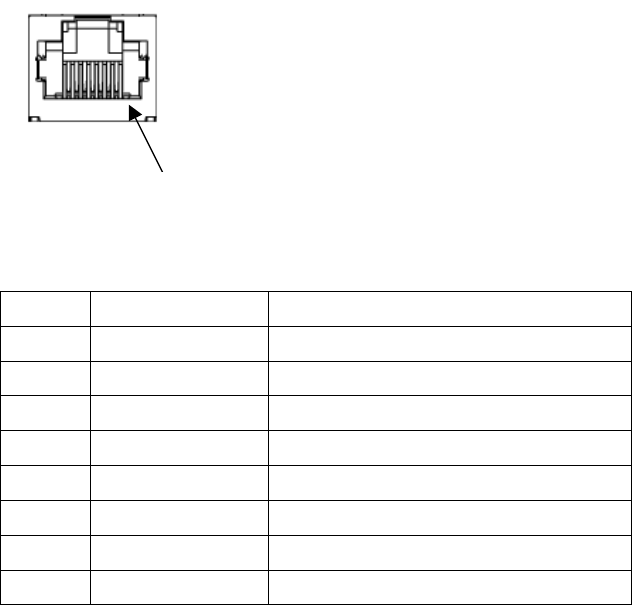
I/O Connector Pin Assignment
PIN NO. SIGNAL NAME DESCRIPTION
1 Ground System Ground
2 TTL Serial Output TTL Serial Data Output from UIC802
3 TTL Serial Input TTL Serial Data Input to UIC802
4 BATT Output +3VDC output from UIC802
5 N.C. No Connection
6 RS232 Output RS232 Serial Data Output from UIC802
7 RS232 Input RS232 Serial Data Input to UIC802
8 Ground System Ground
Pin 1
15 of 15
Regulatory Information
Federal Communications Commission (FCC) Radio Frequency Interference Statement (USA
Only)
This equipment has been tested and found to comply with the limits for a class B digital device,
pursuant to Part 15 of FCC Rules. These limits are designed to provide reasonable protections
against harmful interference in a residential installation. This equipment generates, uses and
can radiate radio frequency energy and, if not installed and used in accordance with the
instructions, may cause harmful interference to radio communications. However, there is no
guarantee that interference will not occur in a particular installation. If this equipment does
cause harmful interference to radio or television reception, which can be determined by turning
the equipment off and on, the user is encouraged to try one or more of the following measures:
1) Relocate the radio or television antenna.
2) Plug the equipment away from the radio or television.
3) Plug the equipment into a different electrical outlet, so that the equipment and the
radio or television are on separate electrical circuits.
4) Make sure that all your peripheral devices are also FCC Class B certified.
5) Make sure you use only shielded cables to connect peripheral devices to your
equipment.
6) Consult your equipment dealer, or an experienced radio / television technician for
help.
WARNING: The system verification tests were conducted with the UIC802 reader unit. Cables
used with this equipment must be properly shields to comply with the requirements of the FCC.
Changes or modifications not expressly approved by Uniform Industrial Corporation could void
the user’s authority to operate the equipment.