unique electronic MS3391 MINI bluetooth barcode reader User Manual
Shenzhen Unique Electronic Int'l Limited MINI bluetooth barcode reader Users Manual
UserManual.wiki
>
unique electronic
>
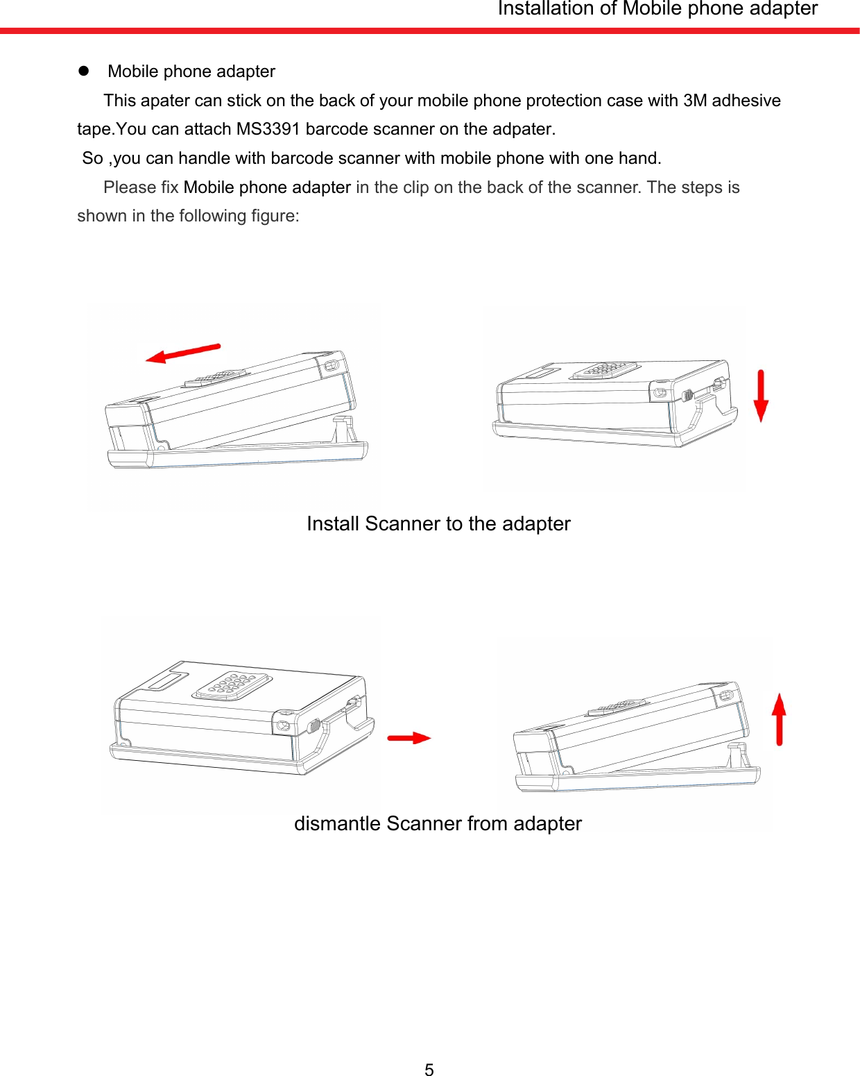
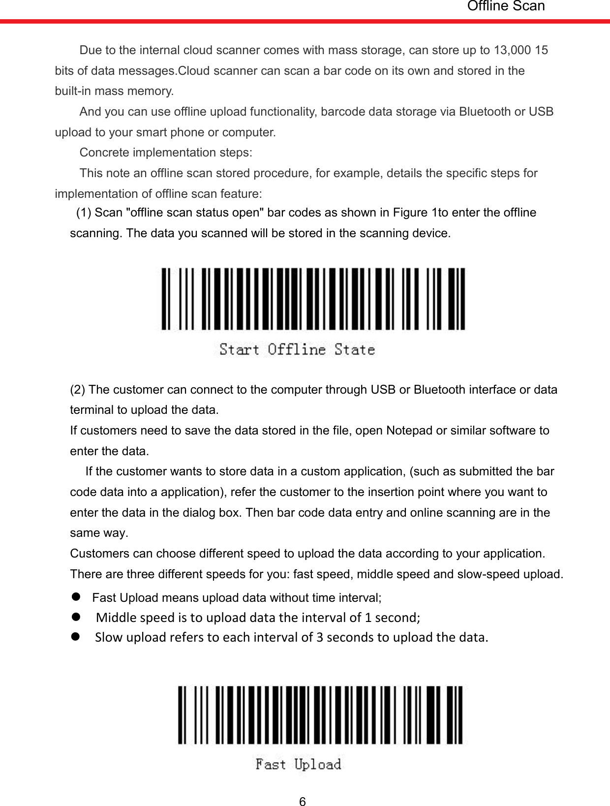
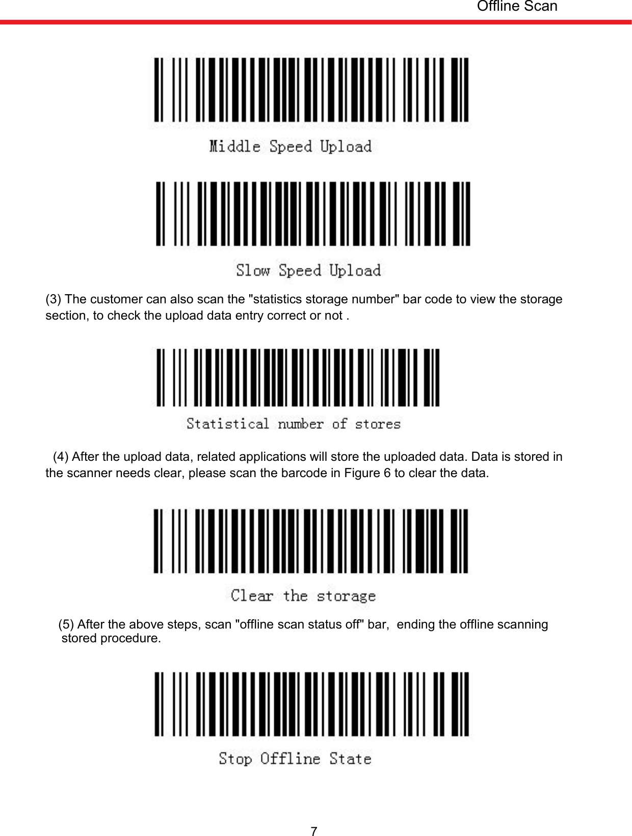
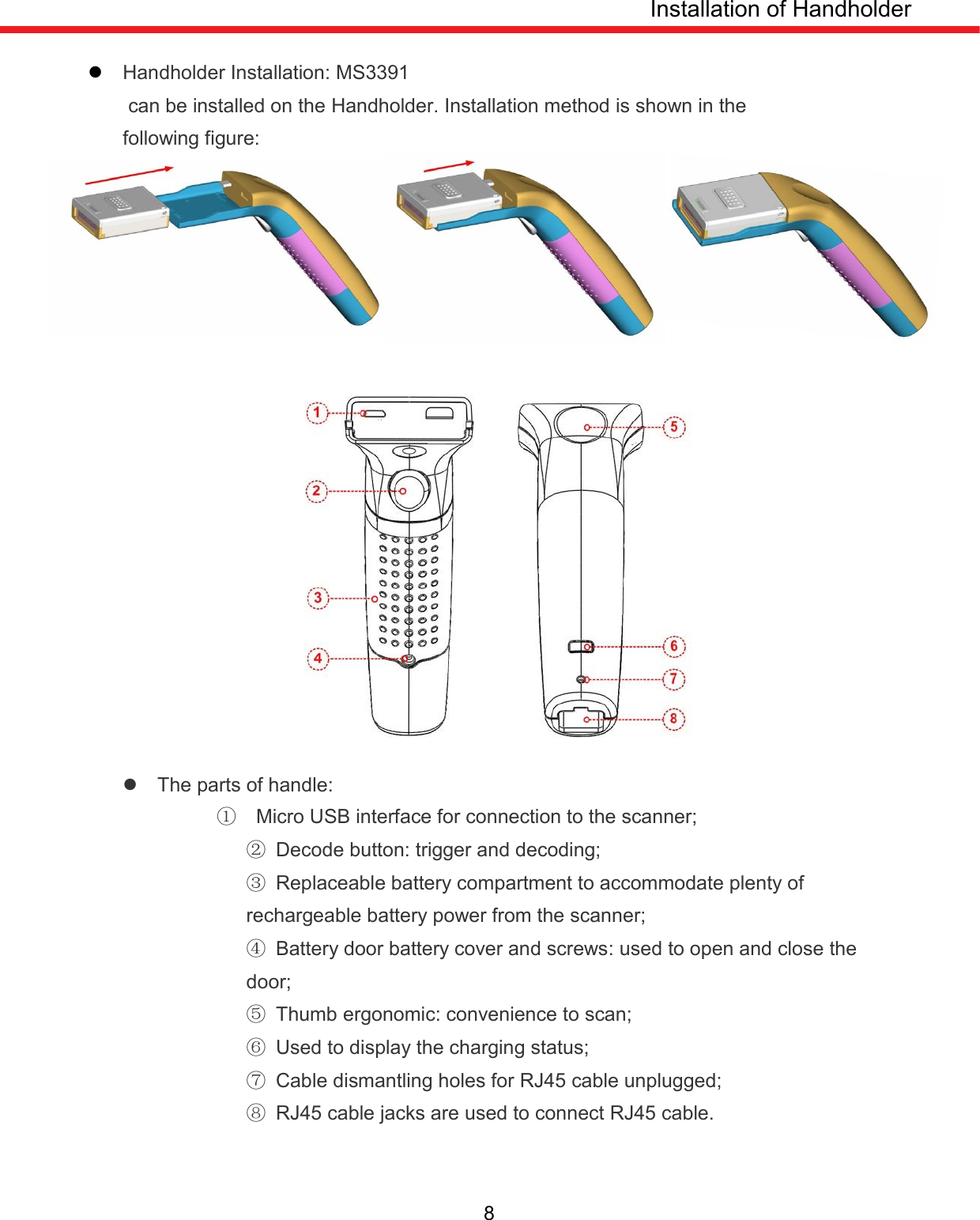
MS3391 User Manual
Users Manual
Navigation menu
Upload a User Manual
Namespaces
Wiki Guide
HTML
PDF
Info
Views
User Manual
Discussion / Help
Navigation