Unitech Electronics HT580 Barcode Scanner User Manual
Unitech Electronics Co., Ltd. Barcode Scanner
Users Manual
Unitech Part Number: 400412 1
Unitech
HT580L Operation Guide
Version 1.0
Unitech Part Number: 400412 2
Overview............................................................................................................................................................ 3
1. SETTING .............................................................................................................. 4
1.1. DATE & TIME.............................................................................................................................................. 4
1.2. Device.............................................................................................................................................................. 5
1.2.1. BACKLIGHT........................................................................................................................................... 5
1.2.2. SCANNER .............................................................................................................................................. 5
1.2.3. AUTORUN.............................................................................................................................................. 6
1.2.4. Memory ................................................................................................................................................... 6
1.3. MODEM......................................................................................................................................................... 6
1.3.1. BAR....................................................................................................................................................... 10
1.3.2. PSWD – Password ............................................................................................................................. 11
1.3.3. SYS – Perform Cold/Warm Start or Update F/W.................................................................................. 11
1.3.4. DIAG - Diagnostics............................................................................................................................... 12
2. COMMUNICATION..............................................................................................13
2.1. USB communication.................................................................................................................................... 13
2.2. BlueTooth communication.......................................................................................................................... 13
2.3. Communication program........................................................................................................................ 15
2.4. Modem communication........................................................................................................................... 17
3. TECHNICAL SPECIFICATION....................................................................19
Model.................................................................................................................................................................... 19
HT580L................................................................................................................................................................. 19
3.1. Pin Assignment......................................................................................................................................... 20

Unitech Part Number: 400412 3
Overview
HT580L operation guide will cover more detail on F/W setting and software development tool
APG580 (Application Generation for HT580L)
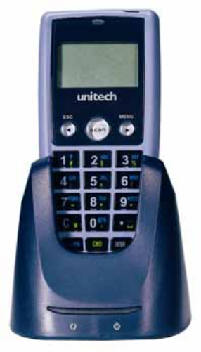
After power on HT580LL, it will show main menu as below
There are 3 options – Setting , Formaching and Run APG580.
HT580L V1.15
1. SETTING
2. FORMCACHING
3. RUN APG580

Unitech Part Number: 400412 4
1. Setting
Setting menu do 2 major functions – User mode setting and Supervisor setting. In HT580L User
Guide, it already explains user mode operation. This document will also repeat it again from below
section.
Note : Due to no barcode scanning requirement on Setting menu, SCAN key will also be
treated as ENTER key during Setting operation. So, user can use below 2 ways to select any
Setting item
Press MENU key to move cursor to target item and then press SCAN(or ENTER) key
Direct press item number (without combining with ENTER) to enter setting item
After pressing “1” key from main screen, there are four setting options which include the following:
1. DATE & TIME
2. DEVICE
3. MODEM
4. SUPERVISOR
1.1. DATE & TIME
Press “1” (or press “MENU” key to move cursor to item 1) to enter DATE & TIME category so that you are
able to set the correct date and time. The page will appear as it is shown below:
Press numeric keys to input correct date & time. Once complete, press [ENTER] to save the revised
settings. To go back to previous menu, press [ESC].
YYYY-MM-DD
2000-01-08
HH-MM-SS
05:50:35
Unitech Part Number: 400412 5
1.2. Device
Use MENU key to move cursor to one of item and then press ENTER (or SCAN key) or directly press
“1” ~ “3” to select target item:
1.2.1. BACKLIGHT
HT580L’s backlight can be automatically on after key pressed and it will automatically off after
predefined period time if there is no more key pressed. Timeout period will be reset if any key is pressed.
In HT580L, timeout period can be set to 10/20/30 or 60 seconds. Or backlight can be set as always OFF
or ALWAYS on.
To set up the backlight, press MENU to adjust the setting. There are below options for choice
Item Description
On 10 SECS Turn on backlight after key-pressing, and then
automatically turn off after 10 seconds
On 20 SECS Turn on backlight after key-pressing, and then
automatically turn off after 20 seconds
On 30 SECS Turn on backlight after key-pressing, and then
automatically turn off after 30 seconds
On 60 SECS Turn on backlight after key-pressing, and then
automatically turn off after 60 seconds
Always Always turn on backlight
Off Always turn off backlight
BACKLIGHT selection : ON 10 SECS/ ON 20 SECS/ ON 30 SECS/ ON 60 SECS/ Always/ OFF
Selecting your preference and press [ENTER] to save the change. To go back to previous menu, press
[ESC].
1.2.2. SCANNER
SCANNER selection: ON NORMAL/ON FLASH/OFF. Press [MENU] key to select your preference and
press [ENTER] (or [SCAN] key) to save the changes. To go back to the previous menu, press [ESC].
Below are explanation for those 3 options
ON
NORMAL Standard operation way (one trigger on scan), scanning
beam will be emitted when press SCAN key and scanning
will be off when releasing SCAN key. Scanning beam will be
also off when it successfully read barcode
ON FLASH Press SCAN (and then immediately), scanner will
automatically continuously emit scanning beam and off
scanning beam until Enter flash mode after press SCAN key
(and then release SCAN key). User can press SCAN key
again to stop Flashing.
OFF Turn off scanner. Scanning beam will not be emitted after
press SCNA key
1. BACKLIGHT
2. SCANNER
3. AUTORUN
4. MEMORY

Unitech Part Number: 400412 6
1.2.3. AUTORUN
AUTORUN is defined to automatically run pre-define FORMCACHING or APG580 program after power
on. Or setup HT580L to back to previous running point before power off. There are below 4 options for
choice. Formcaching Always run Formcaching from beginning after power on
HT580L
APG580 Always run APG580(EasyJob) from beginning after power on
HT580L
RESUME Back to previous running point before power off. This option
is default setting.
OFF Always warm-start after power on. It will back to start menu.
1.2.4. Memory
To display total memory and free memory space.
1.3. MODEM
Unitech provide modem cradle as HT580L’s accessory. So, user can get data through modem if
HT580L is plug into modem cradle.
In general, system administrator need to setup host PC to automatically dial to modem cradle and then
issue command from host to do data communication or remote control. For such configuration, it is
necessary to setup modem to automatically pick phone when host call modem. So, it provides option
“AUTO ANSWER” to setup modem from HT580L.
User can also directly call to remote host PC from modem cradle via HT580L. So, it is necessary to
setup remote PC’s phone number, and then dial out, and then hang up phone if user need to stop
modem communication.
There are below 4 options on MODEM
1.PHONE NUMBER To setup remote modem’s phone number
2.AUTO ANSWER Send ATS0=1 [enter] to modem cradle. So, modem cradle
will automatically pickup phone after one ring tone. You
will get error message if HT580L is not plugged into cradle
or modem cradle is power off.
3.DIAL OUT Dial out according “Phone number” setting. It will send
“ATDT” + phone number
4.HANG OUT Hang up phone (send “+++” and then “ATH”)
Unitech Part Number: 400412 7

Unitech Part Number: 400412 8
FormCaching Specification
DATA FIELD DEFINITION: maximum field number=8
Category Range Description
1. FIELD PROMPT Max.16 characters set field prompting
2. MIN/MAX
Field LENGTH 1-48 set minimum field length
and maximum field length
3. Field type 1.NUMERIC
2.ALPHANUM numeric data (0~9) or alphanumeric data (20H~FCH)
4. DEVICE TYPE 1.KEY ONLY
2.SCAN ONLY
3.BOTH
input by keyboard only,
bar code scanning only or
both
DATA RECORD DEFINITION
Category Range Description
5. Between Field 1.Append Screen
2.Clear Screen 1. Append Screen: Prompt will be displayed on next line
according previous cursor place. If cursor is already on
the last line, it will scroll one line up.
2. Clear Screen: It will clear screen and then display
6. FIELD DELIMITER 1. , 2. ;
3.SPACE 4.TAB
5. FIXED LENGTH
Assign field delimiter, “Fixed Length” mean to store data
according maxi length setting, it will automatically
append spaces to end of field data if length of input
data are less than maxi. length
7. RECORD
DELIMITER 1.CR
2.LF
3.CRLF
assign record delimiter
8. DATE STAMP
FIELD 1.NONE
2.MMDD
3.YYYYMMDD
4.DDMMYY
5.YYYYMMDD
6.DDMMYYYY
assign date stamp and specify the format of date stamp
9. TIME STAMP
FIELD 1.NONE
2.HHMM
3.HHMMSS
4.SSMMHH
assign time stamp and specify the format of time stamp
10. Trasn. Mode 1. Batch
2. Online None
3. Online Multi
T
11. FIELD DELAY 0-6 specify time delay between each record input in second
When FormCaching is enabled, a data file named FORM.DAT will be created in the HT580L.
FORM.DAT stores the data as entered by the user after FormCaching is invoked. The HT580L will not
allow the user to redefine the data fields in FormCaching once the FORM.DAT has been created. The
file FORM.DAT must be deleted in order to implement any change in the configuration of FormCaching.
Running The Resident FormCaching Application Program
Enable the FormCaching, the HT580L built-in application can be ran by switching the portable terminal
to the main menu of operation and selecting “2.FORMCACHING”, select “2.FORMCACHING”. The
FormCaching application program will follow the setting (as previously defined by the user) as it
displays prompts, requests input, and stores data in the FORM.DAT file. Pressing [ESC] key will abort
the current record inputting action.
Unitech Part Number: 400412 9
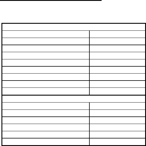
HT580L FormCaching Defaults
The HT580L enables FormCaching by default, the following settings also apply:
DATA FIELD DEFINITION: field number=2
Category Setting
Field #1 FIELD PROMPT ITEM:
DATA LENGTH 20
DATA TYPE ALPHANUM
DEVICE TYPE BOTH
Field #2 FIELD PROMPT QTY:
DATA LENGTH 8
DATA TYPE NUMERIC
DEVICE TYPE KEY ONLY
DATA RECORD DEFINITION
Category Setting
FIELD DELIMITER ,
RECORD FELIMITER CR
DATE STAMP FIELD NONE
TIME STAMP FIELD NONE
FIELD DELAY 1

Unitech Part Number: 400412 10
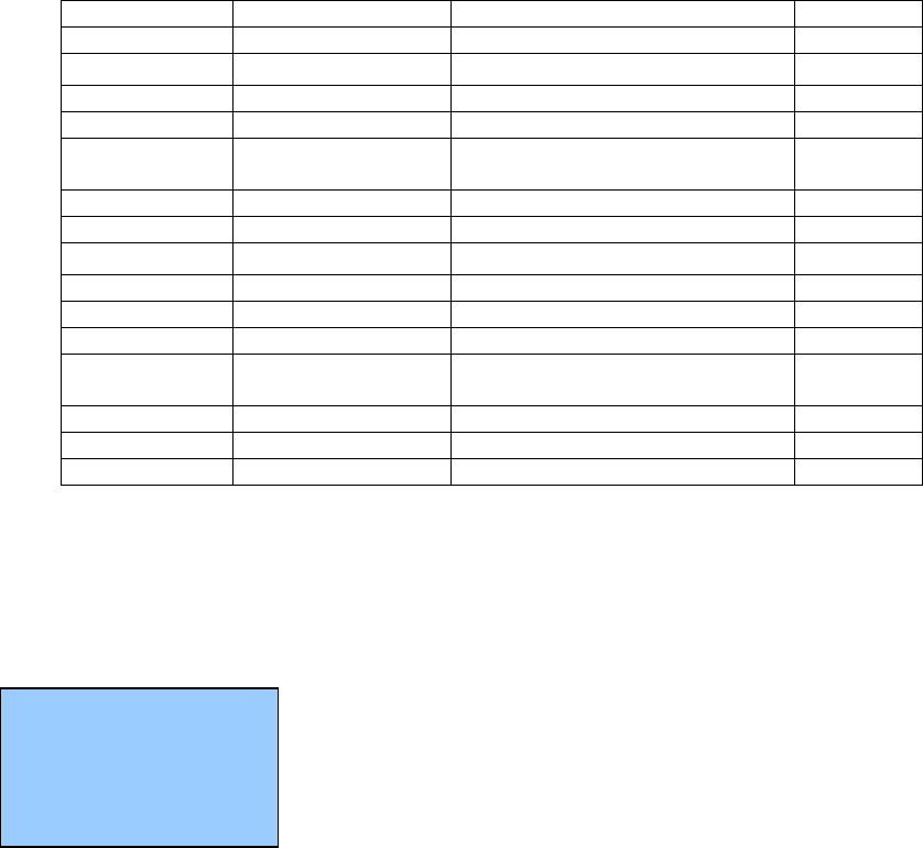
1.3.1. BAR
This option is use to configure individual symbologies for each barcode. After enter configuration menu,
the LCD will display the BARCODE Setup as shown below.
Press [MENU] key to toggle between settings. Press [SCAN] or [ENTER] key to set.
Setup decoding of HT580L supported bar code symbologies
Symbology Function Option Default
Code 39 Decoding ON/OFF ON
full ASCII ON/OFF OFF
Check Digit ON/OFF OFF
Start/stop Character Send/No-send NO SEND
I 2 of 5 Decoding ON/OFF ON
Check Digit OFF/On&Not send/ON&Send OFF
First digit SEND/NOT SEND SEND
Last digit SEND/NOT SEND SEND
Code 32 Decoding ON/OFF ON
First digit SEND/NOT SEND SEND
Last digit SEND/NOT SEND SEND
Matrix 2 of 5 Decoding ON/OFF ON
Check Digit ON/OFF OFF
Industrial 2 of 5 Decoding ON/OFF ON
Codabar Decoding ON/OFF ON
Check Digit ON / ON&Not Send / ON&SEND
/ OFF OFF
CHINA POST Decoding ON/OFF ON
Check Digit ON / ON&Not Send / ON&SEND
/ OFF OFF
CHINA POST Decoding ON/OFF OFF
CHECK DIGIT
MOD SINGLE MOD 10/DOUBLE MOD
10/DOUBLE MOD 11+10 SINGLE
MOD 10
Check Digit ON&Send / ON&NOT SEND OFF
IDATA 2 of 5 Decoding ON/OFF OFF
Check Digit ON / ON&Not Send / ON&SEND
/ OFF OFF
CODE 11 Decoding ON/OFF OFF
Check Digit ON / ON&Not Send / ON&SEND
/ OFF OFF
EAN-13 Decoding ON/OFF ON
ISBN ON/OFF OFF
ISBN ON/OFF OFF
Leading Digit Send/No-send Send
Check Digit Send/No-send Send
EAN-8 decoding ON/OFF ON
Leading digit SEND/NOT SEND SEND
Check Digit SEND/NOT SEND SEND
UPC-A decoding ON/OFF ON
EXPEND to EAN-13 ON/OFF OFF
< BARCODE SETUP>
CODE 39
ON
Unitech Part Number: 400412 11
Leading digit SEND/NOT SEND SEND
Check Digit SEND/NOT SEND SEND
UPC-E decoding ON/OFF ON
UPC-E0 ON/OFF ON
UPC-E1 ON/OFF ON
EXPEND TO UPC-
A ON/OFF OFF
Leading digit SEND/NOT SEND SEND
Check Digit SEND/NOT SEND SEND
CODE 93 decoding ON/OFF OFF
Code 128 decoding ON/OFF ON
EAN128 ON/OFF ON
EAN128 CODE ID ON/OFF OFF
EAN128 FUNC CH NOT SEND/SEND NOT
SEND
TELPEN decoding ON/OFF ON
UK PLESSEY decoding ON/OFF OFF
Check Digit SEND/NOT SEND SEND
1.3.2. PSWD – Password
Change Supervisor password – The default password is “580”
1.3.3. SYS – Perform Cold/Warm Start or Update F/W
There are 4 options on this item – Warm Start, Cold Start, Update
F/W and Update Decoder
Warm Start : warm boot HT580L
Cold Start : All of data and setting will be set to system default
Update F/W : Update F/W version. You can get the latest F/W
image from supplier, F/W will be compressed as ZIP file. There are 8 files after unzip it –
bank0.bin ~ bank7.bin. You can use communication program to send those 8 files into HT580L
and then execute this option to update F/W. Please refer to Section Communication to know
more detail information for communication program.
1. WARM START
2. COLD START
3. UPDATE F/W
4. UPDATE DEC

Unitech Part Number: 400412 12
1.3.4. DIAG - Diagnostics
The HT580L has a built-in diagnostics program to test the terminal's hardware. The test routines are
data destructive. Therefore, before running the diagnostic program, make sure you back up the data
in the HT580L.
Note : When a H/W or S/W service has been made on the PT630, such as maintenance, repair or upgrade, it
is strongly recommended to run the diagnostic program.
At the Supervisor Mode menu:
1. Press 7 (7.DIAG), then LCD will display the diagnostic menu as
shown on the left. Select 1-8 to run the desired diagnostic routine
1. VER : Get F/W version for HT580L and Decoder.
2. SCAN : test bar code input by scanning bar code labels. Press ESC key to return to the
diagnostics menu.
3. LCD : Darken the dots of the LCD screen and cycle power to the LCD backlight to check
if the LCD functions OK
4. COMM : Connect to PC’s communication testing program to test USB/RS232
communication
5. PWR : Testing Battery power
6. KEY : Test every key response
7. RTC : Show Current time/date is displayed
8. MEM : Test RAM condition
Note : Please refer to Service manual for more detail information.
1. VER 2. SCAN
3. LCD 4. COMM
5. PWR 6.KEY
7. RTC 8.MEM

Unitech Part Number: 400412 13
2. Communication
2.1. USB communication
To connect HT580L to PC via USB, you need to install USB driver which will redirect
data to virtual COM port. You can get USB driver from HT580L CD.
Window OS will prompt new device dialog box when PC is the first time to be connected
to HT580L via USB. Please re-direct driver folder to Unitech’s USB driver folder and
then follow its prompting to install driver.
Then you can check correct COM port number from Control Panet System
Hardware Device manager, then you can find correct COM number from “USB
Serial Port” under option “Connection Port(COM and LPT)”
In HT580L, you should change it default communication port to “RS232/USB” from
Setting Supervisor Comm Port
2.2. BlueTooth communication
To do BlueTooth communication, you should change HT580L’s port setting to
BlueTooth from Setting Supervisor Comm Port
In PC, you should connect Bluetooth dongles if there is no Bluetooth support. And
Bluetooth driver should be pre-install.
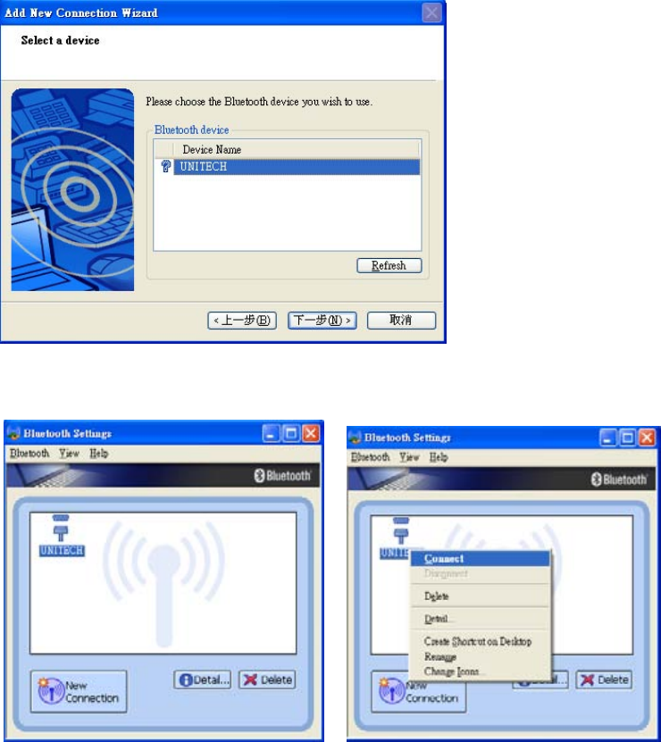
Then , you must follow up below steps on you rPC
1. Power on HT580L and then Run Bluetooth manager from PC
2. Click “New Connection” buttom
3. Select proper mode – Express Mode or Customer Mode. User can specify COM port
number if select customer mode.
Unitech Part Number: 400412 14
4. Then it will search all of Bluetooth device within BT converge area and then list them
down on the screen. You can find all of HT580Ls will be displayed as “UNITECH”.
Then you can click “Next” button
5. Then it will prompt user to enter PIN code, HT580L’s default PIN (Pass key) is “0580”,
then you can find this HT580L is already on your Bluetooth list. Then click right mouse
button to connect it.
6. You can also check the correct PORT number from “Detail”
PS. HT580L’s BT Device name is fixed on “UNITECH”, so you will see a lots of
“UNITECH” on Bluetooth Manager if you want to connect several HT580Ls to single PC.
And user can not identify which one is correct HT580L to map to list. So, it is suggested to
power on one HT580L at a time when make connection and please note its MAC address
from DETAIL.
Unitech Part Number: 400412 15
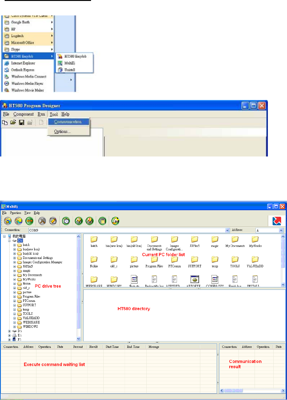
2.3. Communication program
In Easy Job, it also bundle one communication program named “MultiEj”. You can directly run it from
HT580L EasyJob
Or it from HT580L Easy Job and then then select Tool Communication as below diagram
Then it will launch MultiEj program as below screen, You can directly
1. drag and drop files from PC folder to HT580L directory to execute download function
2. drag and drop files from HT580L directory to PC folder to execute upload function
3. directly select files on HT580L directory area and delete.
Unitech Part Number: 400412 16
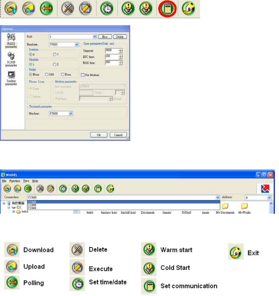
Before using MultiEj to do communication, you should setup correct port number and communication
parameter by chick Options icon on menu bar.
Then click “NEW” button to select a new COM port, then configure its proper communication
parameter and click OK button to finish setting. Then you can select proper port from Connection
List Box
After select proper COM port, you will find icons of Date/Time , WarmStart and ColdStart changed
from grey to color icon.
Download / Upload / Delete / Execute will also become color if you select click files on local file
area or remote files area
Unitech Part Number: 400412 17
2.4. Modem communication
For HT580L, Unitech provide modem cradle to enable modem communication function between PC and
HT580L. So, user must connect phone line to cradle and HT580L still connect to cradle with RS232
interface.
There are 2 ways to do connection.
1. Calling from PC
2. Calling from Terminal
Call from PC
To call modem from PC, HT580L’s modem cradle should be set to automatically pick up external call.
So, you should put HT580L into cradle (cradle should be connect to power) and execute Setting
Modem and then select “AUTO ANSWER” to let HT580L send “ATS0=1” to modem board (inside
cradle). Then, cradle can automatically pick up external calling after one ring tone. (After execute
“AUTO ANSWER”, it is not suggested to power off cradle, or “Auto Answer” function will be
disappeared)
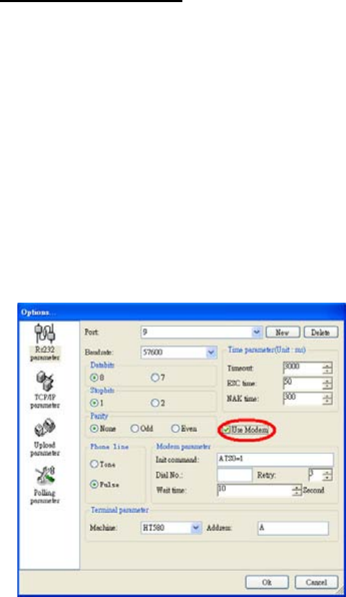
In PC, you can use MultiEj to do modem communication with HT580L, you can setup modem function
from Options by check “Modem” check
Then setup to correct Initial command, dial number, and wait time.
Call from HT580L
Current, HT580L can support modem dial from F/W. We will provide modem function from EasyJob
in the future.
In PC side, you can use Hyperterminal to setup modem Auto Answer. And please put HT580L into
cradle and phone line should be connected to cradle. Then follow up below step
4. Execute Setting Modem Phone to input correct phone number
5. Then execute Setting Modem Dial out to connect to remote
After end of communication, execute Setting Modem Hang to hang up phone.
Unitech Part Number: 400412 18

Unitech Part Number: 400412 19
3. Technical Specification
Model HT580L
Dimensions 123mm x 55mm x 25mm
Weight 150g
Drop Specification 1.2M free drop to concrete floor
Display 128 x 64 pixel; 16x8 characters or 12x4 characters
Battery One 3.7V 730mAH Li-ion battery
Environmental Sealing IP42
Operation Temperature 0°C~50°C
Storage Temperature -20°C ~70°C
Humidity 5% to 95% RH, ; not condensed
Electrostatic Discharge
(ESD) 4 KV contact discharge
8 KV air discharge
Back-Lit Display Yes
Keypads 18 alphanumeric keys including one scan trigger
CPU ST UPSD3354DV
Operating System Proprietary ( C Language)
Memory 1 MB for main program & data storage
Application Development EZ Job
Communication RS232/USB1.1/ Bluetooth/Modem
Battery Life Up to 8 hours
Symbologies UPC/EAN, Code 39, Interleave 2 of 5, CODABAR, MSI, Code
128, Code 93, Code 32,China Postal Code
Buzzer Yes, over 75 dB
One LED Reading – green color

Unitech Part Number: 400412 20
3.1. Pin Assignment
The HT580L communicate via the RS232 communication port located on the bottom of the unit. You can
connect the unit via the communication cable to PC RS232 jack for data transfer or connect through
cradle for communication.
Pin Name
1 US-POWER
2 GND
3 DC-IN
4 USB DP
5 CTS
6 RTS
7 DSR
8 GND
9 DTR
10 TXD
11 RXD
12 USB DP
Unitech Part Number: 400412 21
Federal Communication Commission Interference Statement
This equipment has been tested and found to comply with the limits for a Class B digital device, pursuant
to Part 15 of the FCC Rules. These limits are designed to provide reasonable protection against harmful
interference in a residential installation. This equipment generates, uses and can radiate radio
frequency energy and, if not installed and used in accordance with the instructions, may cause harmful
interference to radio communications. However, there is no guarantee that interference will not occur in
a particular installation. If this equipment does cause harmful interference to radio or television reception,
which can be determined by turning the equipment off and on, the user is encouraged to try to correct
the interference by one of the following measures:
Reorient or relocate the receiving antenna.
Increase the separation between the equipment and receiver.
Connect the equipment into an outlet on a circuit different from that to which the receiver is
connected.
Consult the dealer or an experienced radio/TV technician for help.
FCC Caution: Any changes or modifications not expressly approved by the party responsible for
compliance could void the user's authority to operate this equipment.
This device complies with Part 15 of the FCC Rules. Operation is subject to the following two conditions:
(1) This device may not cause harmful interference, and (2) this device must accept any interference
received, including interference that may cause undesired operation.
This device and its antenna(s) must not be co-located or operating in conjunction with any other antenna
or transmitter.