Unitech Electronics MS840BC Wireless Cradle User Manual MS840 UM V1 0 1
Unitech Electronics Co., Ltd. Wireless Cradle MS840 UM V1 0 1
UserManual.wiki
>
Unitech Electronics
>
MS840BC User Manual
User manual(Rev1.0)
Navigation menu
Upload a User Manual
Namespaces
Wiki Guide
HTML
PDF
Info
Views
User Manual
Discussion / Help
Navigation


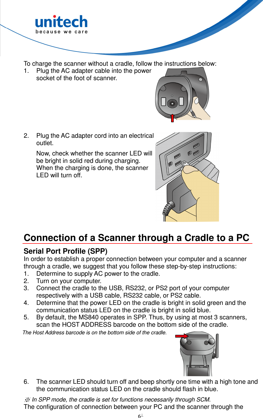
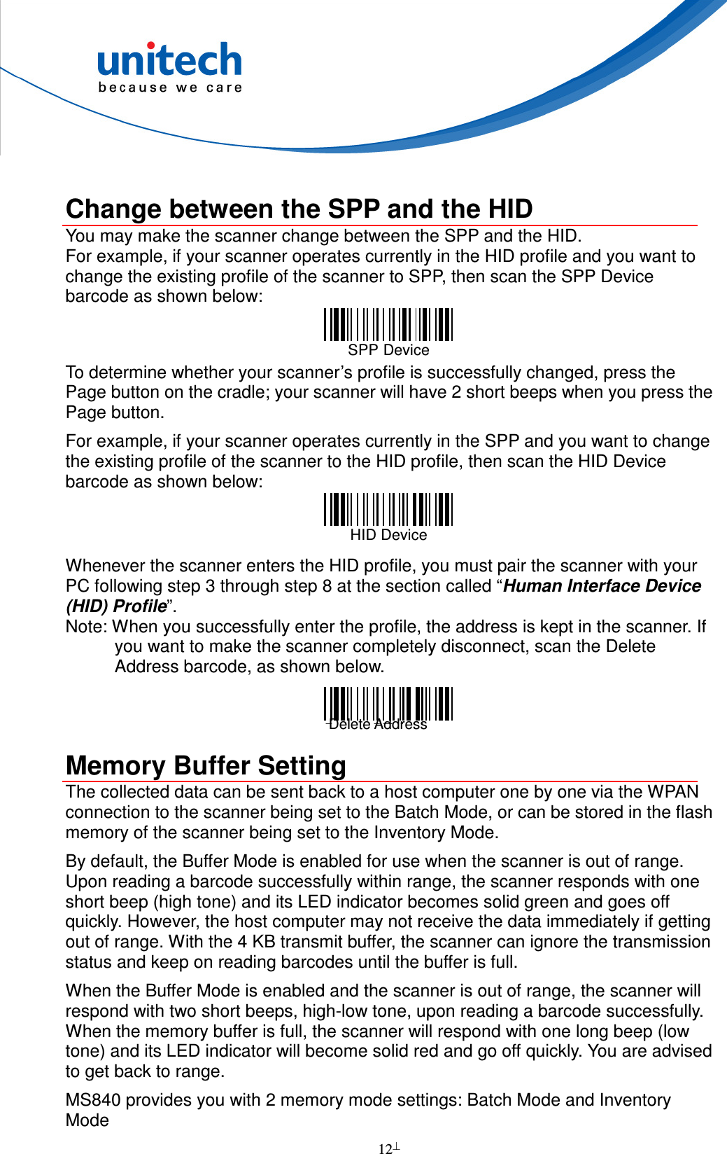
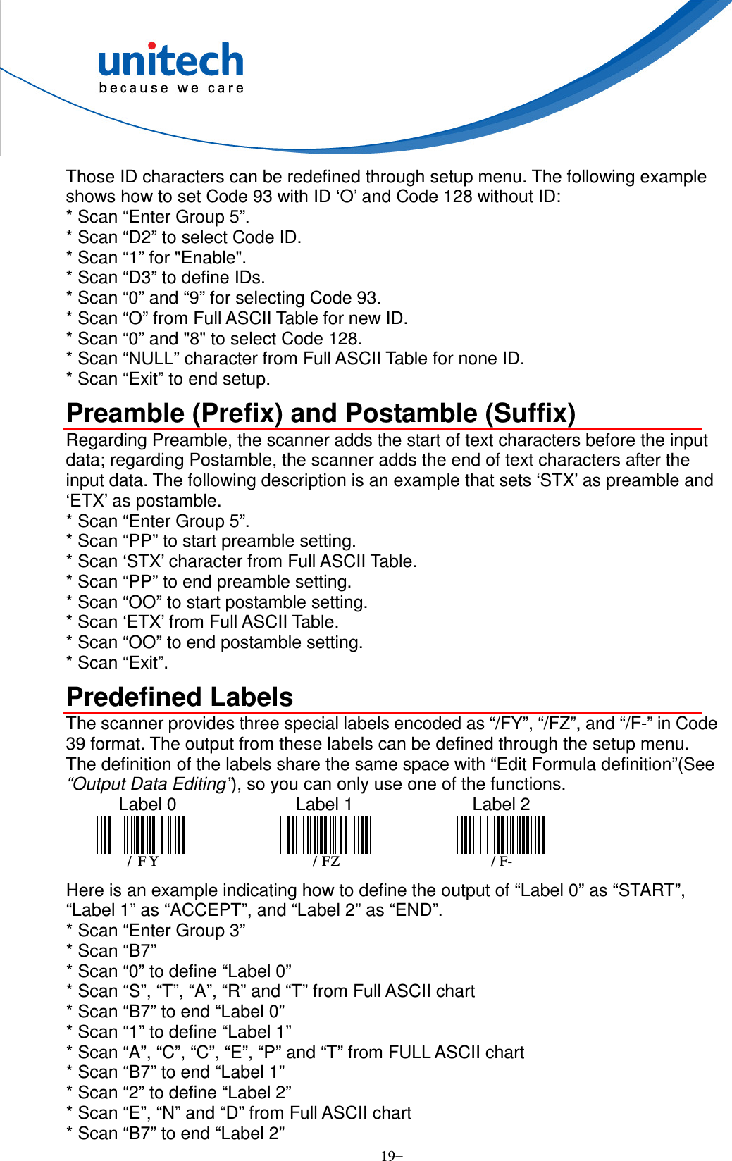
![2 Content - Scanner user has Wireless laser scanner * 1 Power adapter (1010-601959G) for scanner * 1 User's manual CD * 1 Quickly reference guide * 1 Scanner/cradle user has Wireless laser scanner * 1 Cable (PS2/USB/RS232) (optional) * 1 Cradle * 1 Power adapter (1010-900008G) for cradle * 1 User's manual CD * 1 Quickly reference guide * 1 Note: 1. The items included in the package may be different, depending on your order. Save the box and packaging material for future use in case you need to store or ship the scanner. 2. When you receive and unpack the package at first time, if an item above is lost, please contact the dealer you bought from, immediately. 3. Environment temperature for charging should be in 0°C - 40°C. 4. Up to 3 scanner devices work with only 1 host PC through 1 cradle or wireless receiver. 5. The scanner’s default power off (idle mode) time is 1 min. 6. When you use the scanner for the first time, the scanner must be charged continuously for 4.5 hours. [Scanner Body Aspect] LED Lamp Scanner Window Trigger Cradle Detecting Points for Charge Reset Pinhole](https://usermanual.wiki/Unitech-Electronics/MS840BC/User-Guide-1570507-Page-11.png)
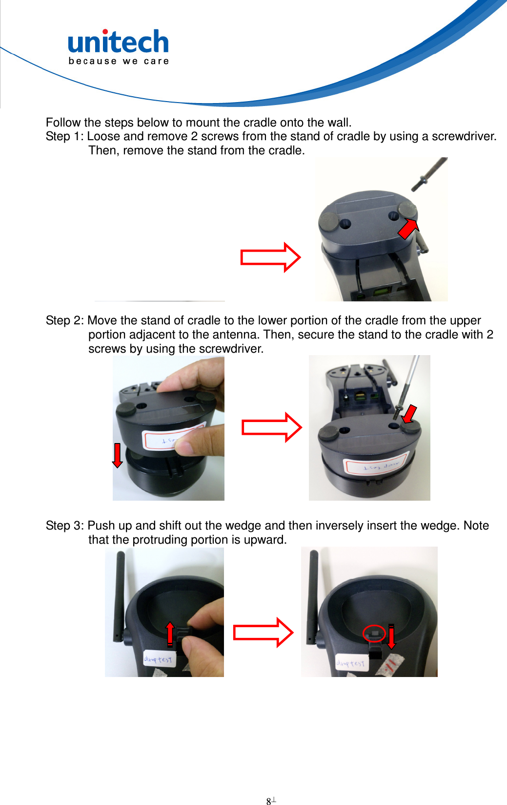
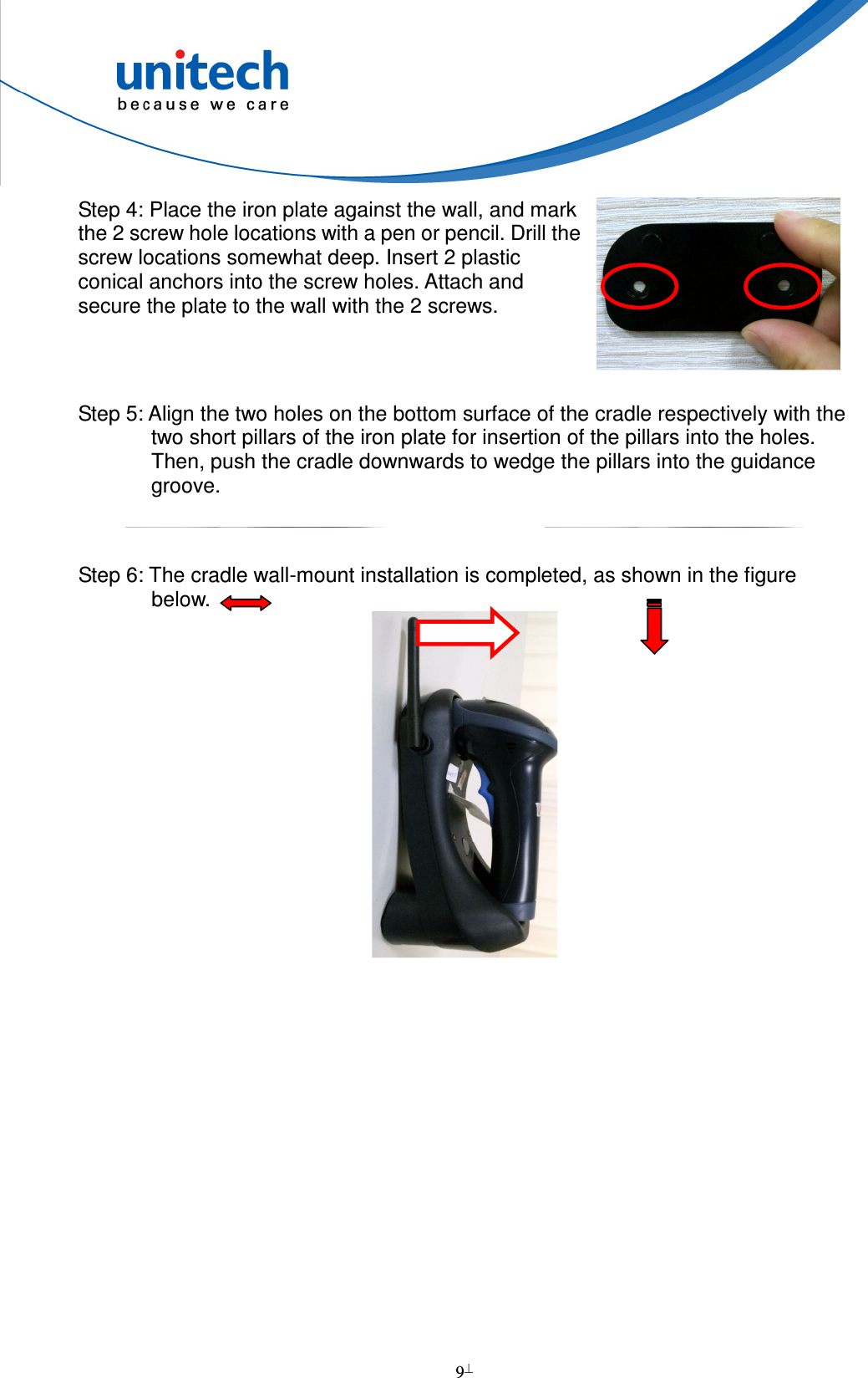
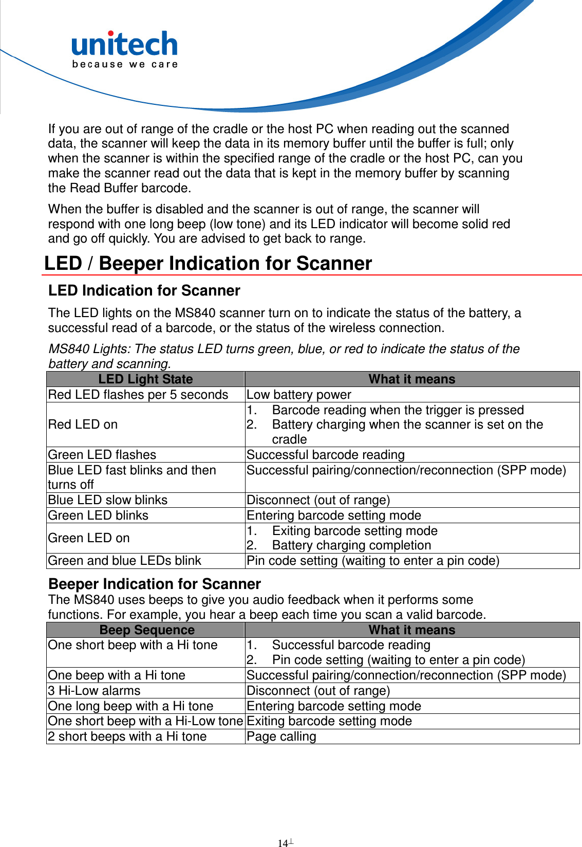
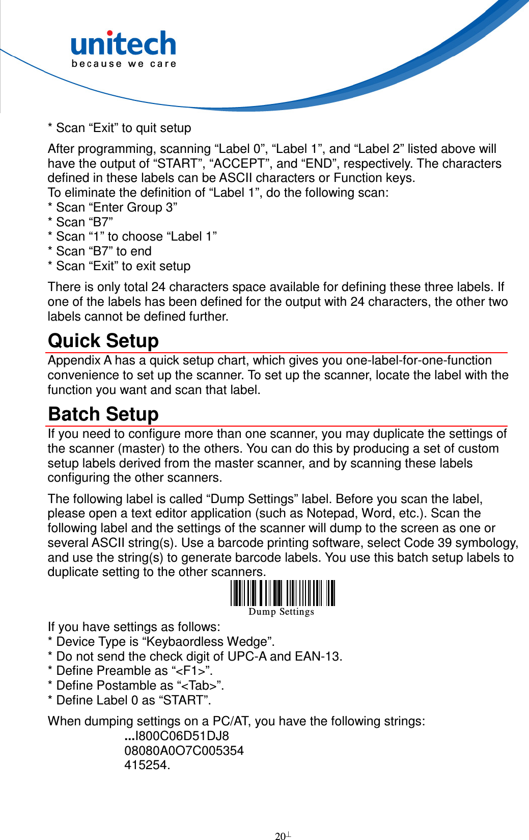
![3 [Cradle Aspect] Note: 1. If you remove the wedge and flip it upside down, it acts as a clip to hold up the scanner when the base is mounted to the wall. 2. The cradle foot serves for table mount when being fixed to the upper portion adjacent to the antenna; the cradle foot serves for wall mount when being fixed to the lower portion on the guidance grooves. 3. When the interface switch is pushed to the left side (default), a keyboard can be connected with the PS2 cable to the cradle to work with the cradle; when the interface switch is pushed to the right side, the keyboard, even if connected with the PS2 cable to the cradle, cannot work. 4. The guidance groove is designed for arrangement of the power cord and the communication cable (USB/RS232/PS2).USB Cable Power Adapter Communication Status LED Power LED Page Button Antenna Scanner Detecting Points for Charge USB/RS232/PS2 Socket PS2 Cable RS232 Cable Wedge Note 1 Host Address Power Socket Cradle Foot Note 2 Reset Pinhole Guidance Groove Note 4 Interface Switch Note 4](https://usermanual.wiki/Unitech-Electronics/MS840BC/User-Guide-1570507-Page-12.png)


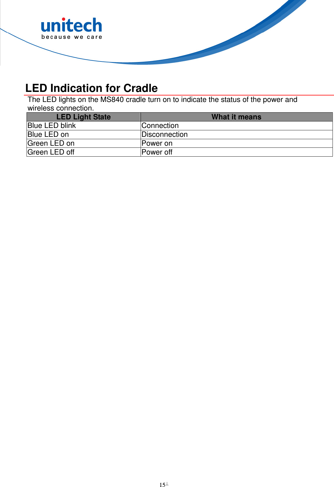

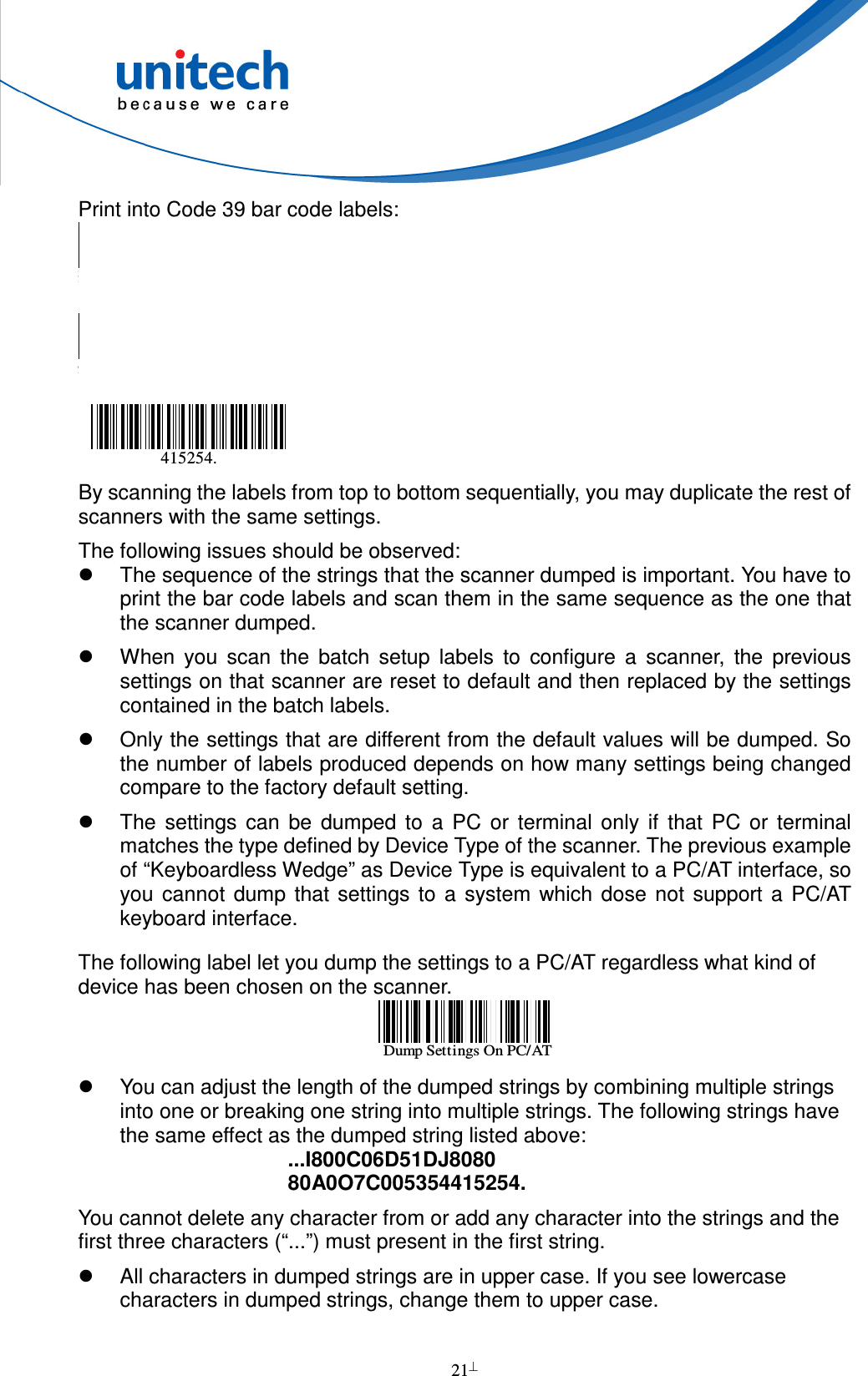
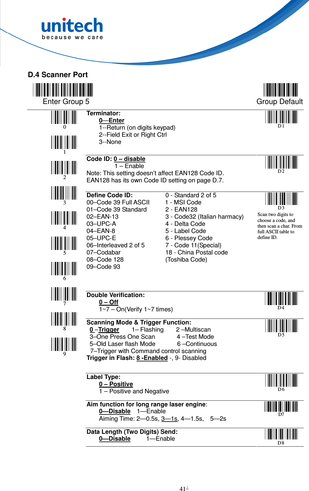
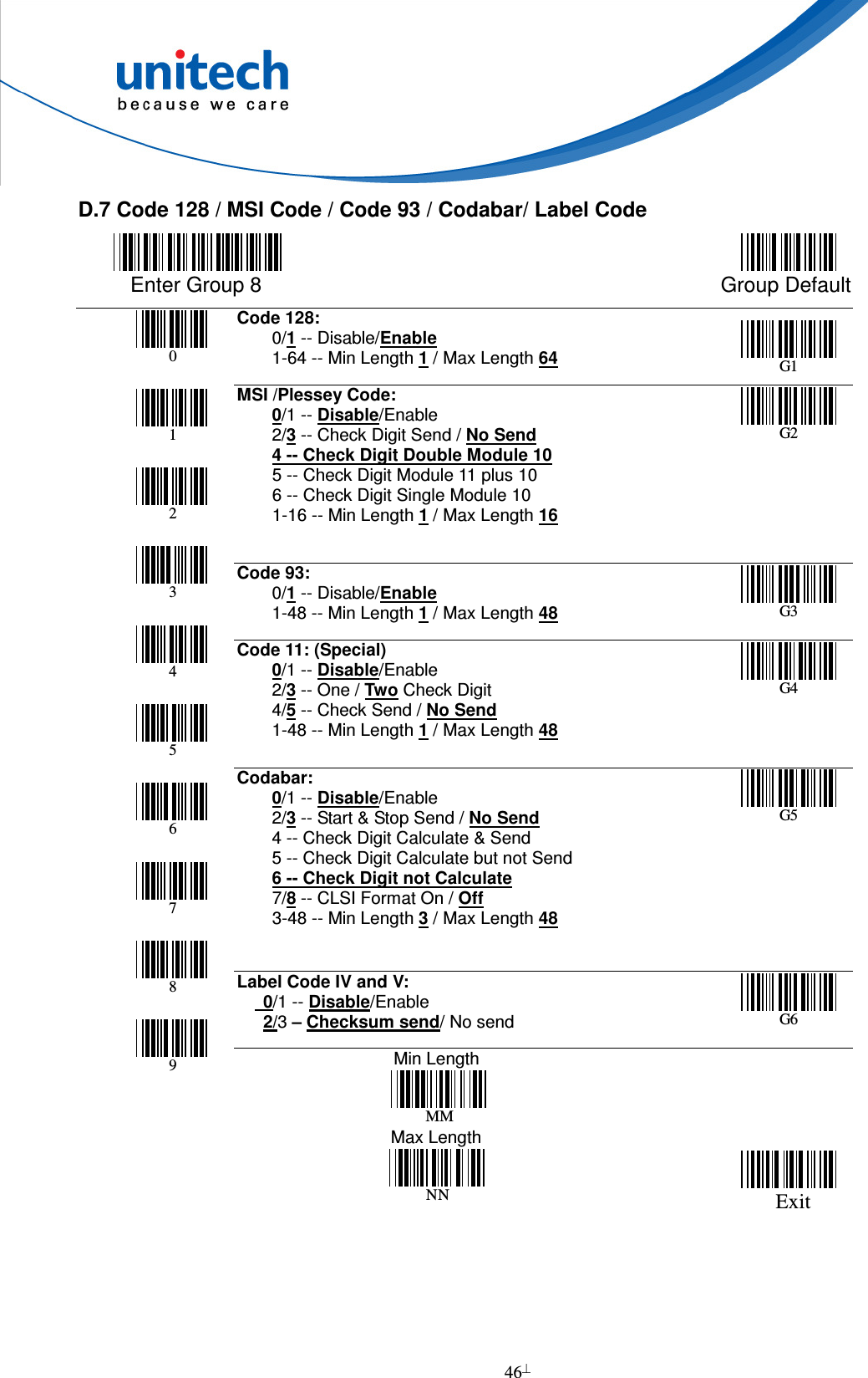
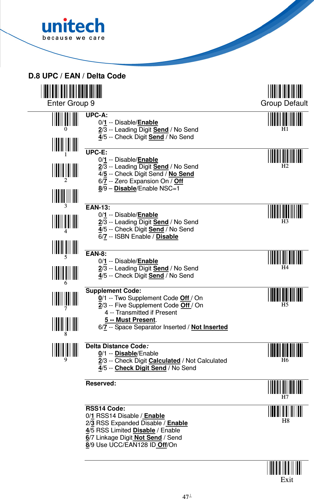
![18 Barcode Length Setting The following example illustrates how to set Code 39 with a minimum length of 5 and a maximum length of 20. * Scan “Enter Group 7”. * Scan “F1” to select Code 39. * Scan “MIN LENGTH” to enter minimum length setting. * Scan “0” and “5” to select length 5. * Scan “MIN LENGTH” to end minimum length setting. * Scan “MAX LENGTH” to enter maximum length setting. * Scan “2” and “0” to select length 20. * Scan “MAX LENGTH” to end maximum length setting. * Scan “Exit” to end setup. Code ID Setting Each barcode symbology supported by the scanner has a default ID character defined below. If you don’t know what the label that you’re scanning is, you may use this feature to identify. Symbology Pre-Defined UPC-A A UPC-E E EAN-13 F EAN-8 FF I 2 of 5 I S 2 of 5 H Code 39 M Codabar N Code 93 L Code 128 K UCC/EAN128 ]C1 MSI O Code 32 T Delta Code D Plessey Code P Label Code IV,V B China Postal Code C](https://usermanual.wiki/Unitech-Electronics/MS840BC/User-Guide-1570507-Page-27.png)
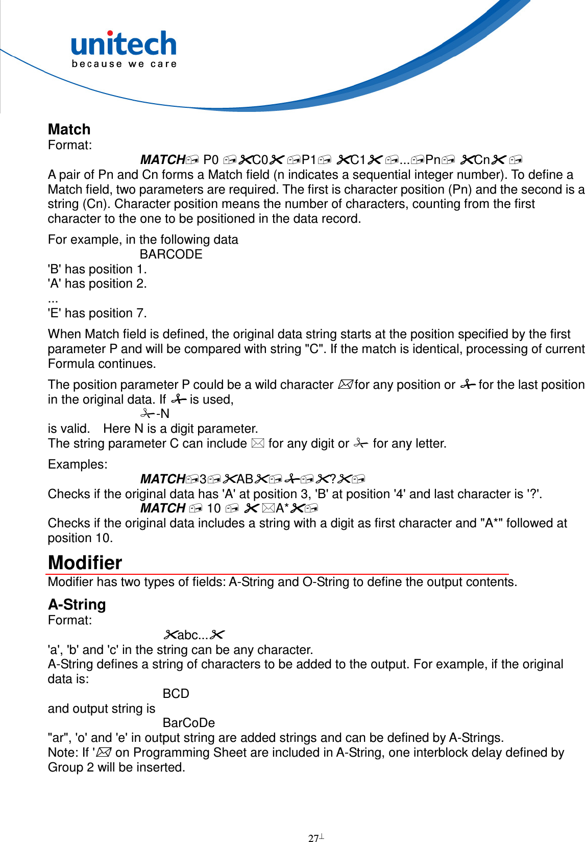
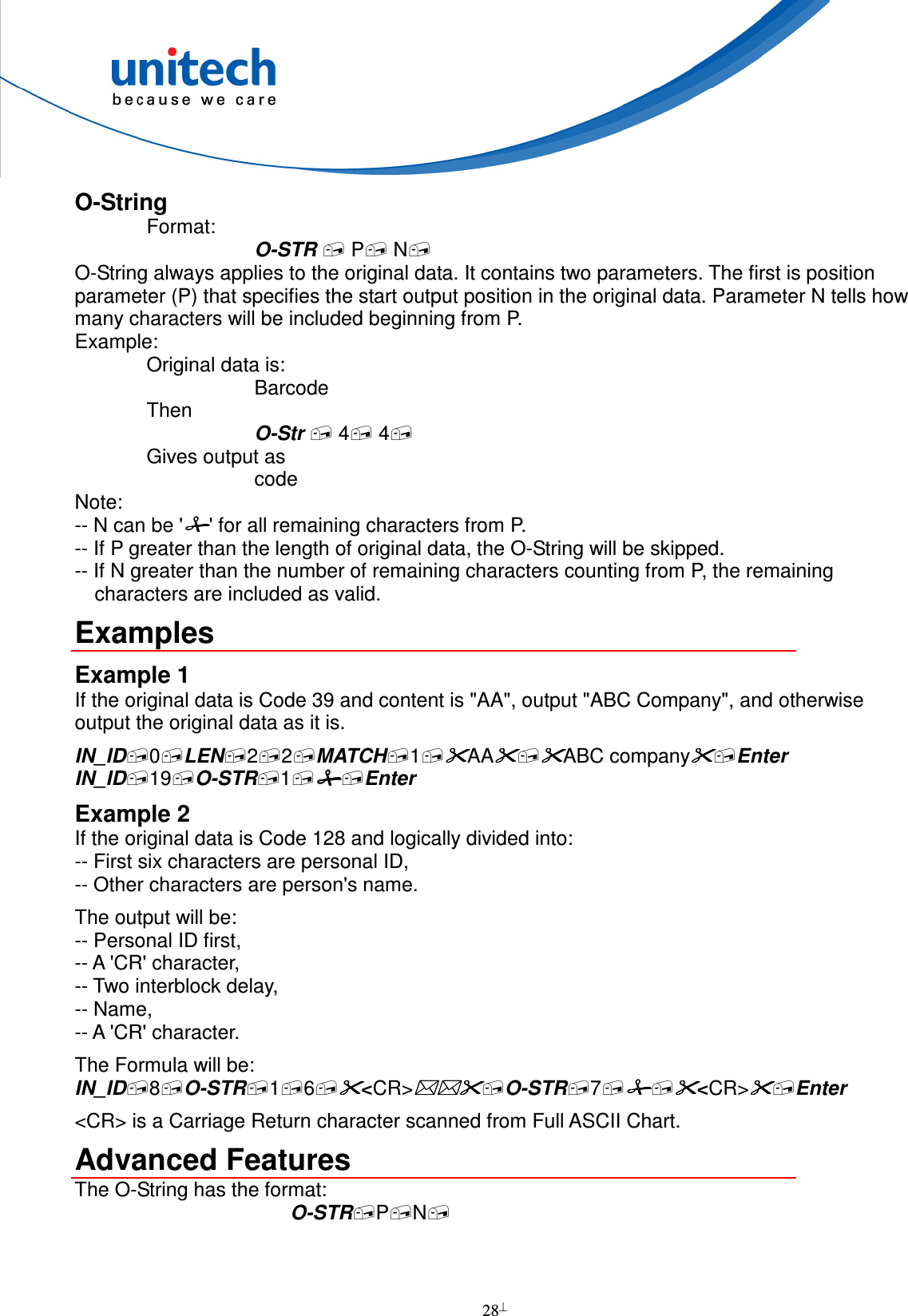
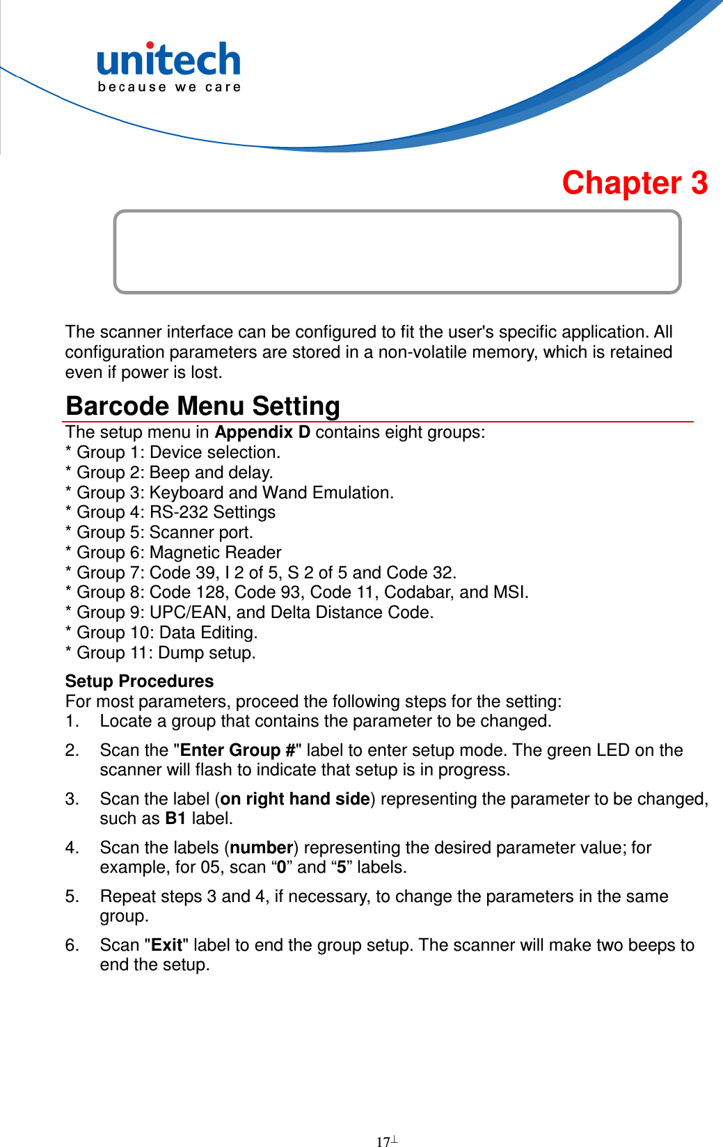
![29 Both parameters of O-String mentioned above are numbers. But both parameters can be specified as strings. If N is a string, it becomes a position and the meaning of O-String will be "Output from position P to position N". If P is defined as: "ab...ik" a, b, I, and k can be any character, the position will be evaluated as -- Start from the first position of the original string and search character 'a'. -- From the position next to 'a' in original data, search for 'b'. -- .... -- From the position next to 'i', search for k. -- If above searches are all found, the result of the parameter will be the position where 'k' is located. If N is a string, the position evaluation of N is the same as P except that the searching position is starting from P+1. For both P and N, if string is defined, a value can be added to or subtracted from the position. That following O-Strings: "ab...ik"+M, and "ab...ik"-M, are meaningful. M is an integer number. Example: Suppose the following is a message to be modified: %B012345678901234^ABEL/STEVE L MGR ^90010129999999? In this message: "%" is start sentinel. "012345678901234" is account number. "^" is a separator 6. "ABEL" is surname. "/" is a separator. "STEVE" is first name. "L" is initial. "MGR" is title "^" is a separator. "9001" is expiration date. "?" is end sentinel. The output sequence desired is: Surname, First Name [CR] Account Number [CR] Expiration Date [CR] The formula input will be: IN_ID0O-STR^+1/-1,O-STR/+1<SP>-1<CR>O-STR3^-1<CR>O-STR^^+14<CR>Enter Here <SP> is Space character and <CR> is Carriage Return character.](https://usermanual.wiki/Unitech-Electronics/MS840BC/User-Guide-1570507-Page-38.png)
![30 The output of above input will be ABEL,STEVE[CR] 012345678901234[CR] 9001[CR]](https://usermanual.wiki/Unitech-Electronics/MS840BC/User-Guide-1570507-Page-39.png)


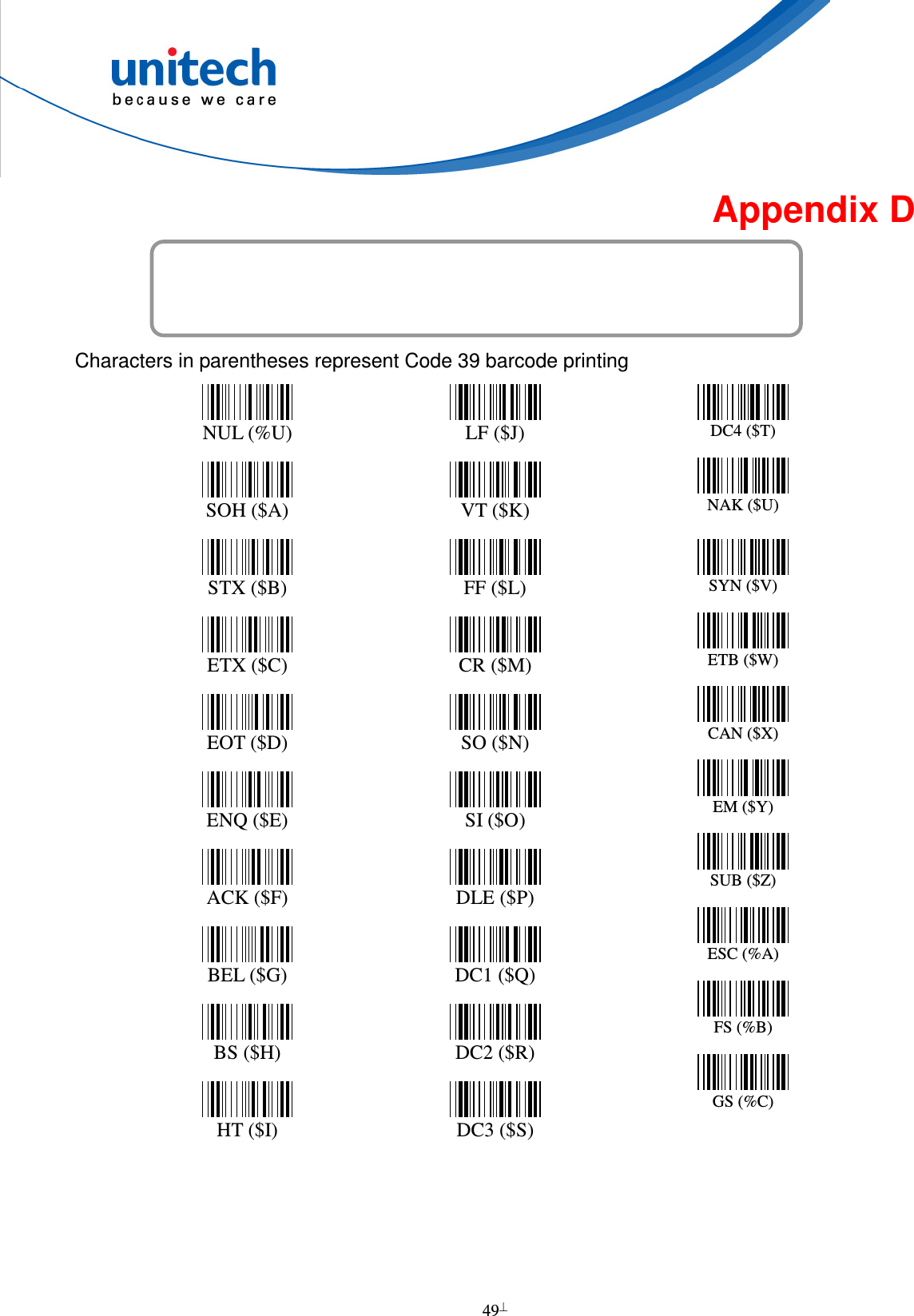
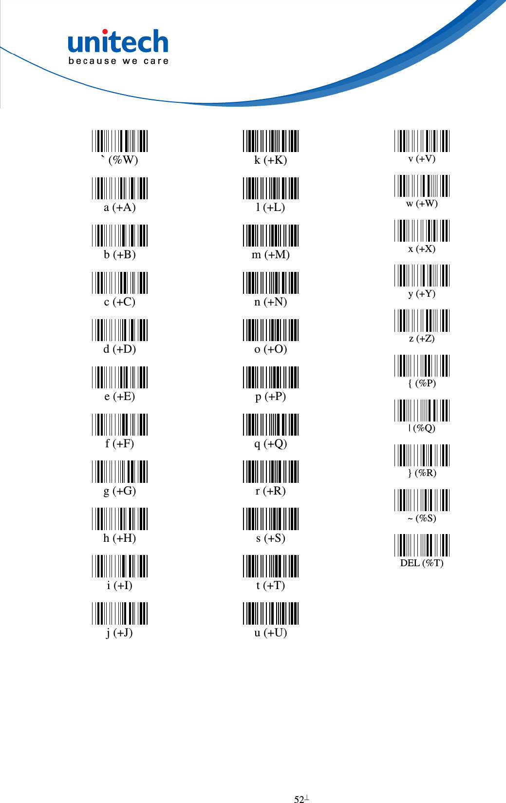
![51 ? (%J) @ (%V) A B C D E F G H I J K L M N O P Q R S T U V W X Y Z [ (%K) \ (%L) ] (%M) ^ (%N) _ (%O)](https://usermanual.wiki/Unitech-Electronics/MS840BC/User-Guide-1570507-Page-60.png)