Unitech Electronics MS84XG Dongle for MS84X wireless scanner User Manual
Unitech Electronics Co., Ltd. Dongle for MS84X wireless scanner
UserManual.wiki
>
Unitech Electronics
>
MS84XG User Manual
User Manual
Navigation menu
Upload a User Manual
Namespaces
Wiki Guide
HTML
PDF
Info
Views
User Manual
Discussion / Help
Navigation
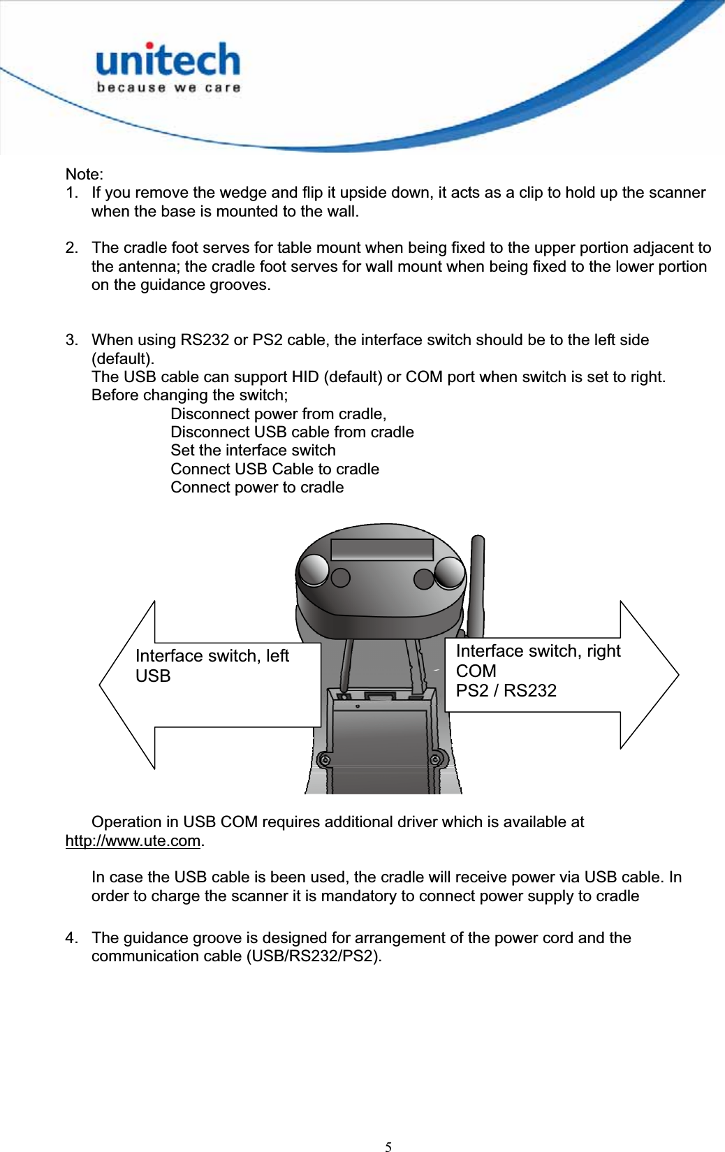
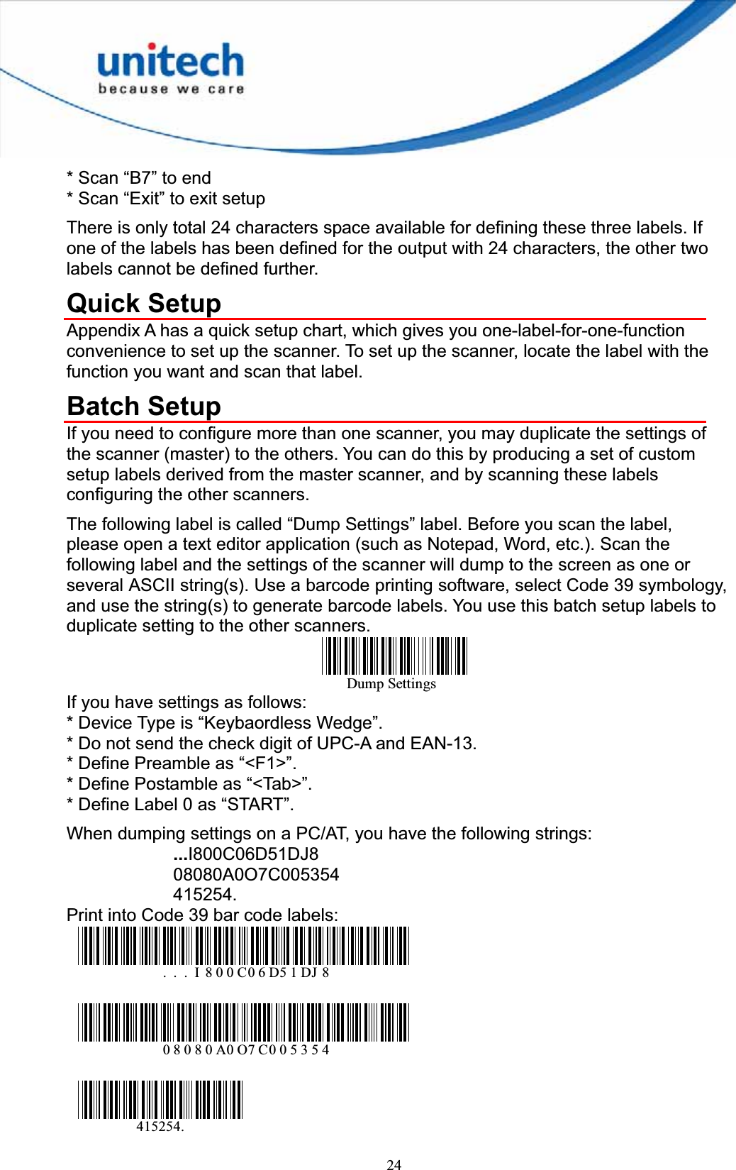
![4[Scanner Body Aspect]1 LED indicator 2 Scanner Grip 3 Laser Exit Window 4 Trigger 5 Scanner Contact Points for Charge 6 Reset Pinhole [Cradle Aspect]1 Antenna 2 Communication Status LED 3 Page Button 4 Wedge Note 1 5 Power LED 6 Cradle Contact Points for Charge 7 Cradle Foot Note 2 8 Cradle address barcode 9 Interface Switch Note 310 USB/RS232/PS2 Socket 11 Reset Pinhole 12 DC Power Socket (5V) 13 Guidance Groove Note 4 12345625316104812711139](https://usermanual.wiki/Unitech-Electronics/MS84XG/User-Guide-2004494-Page-13.png)
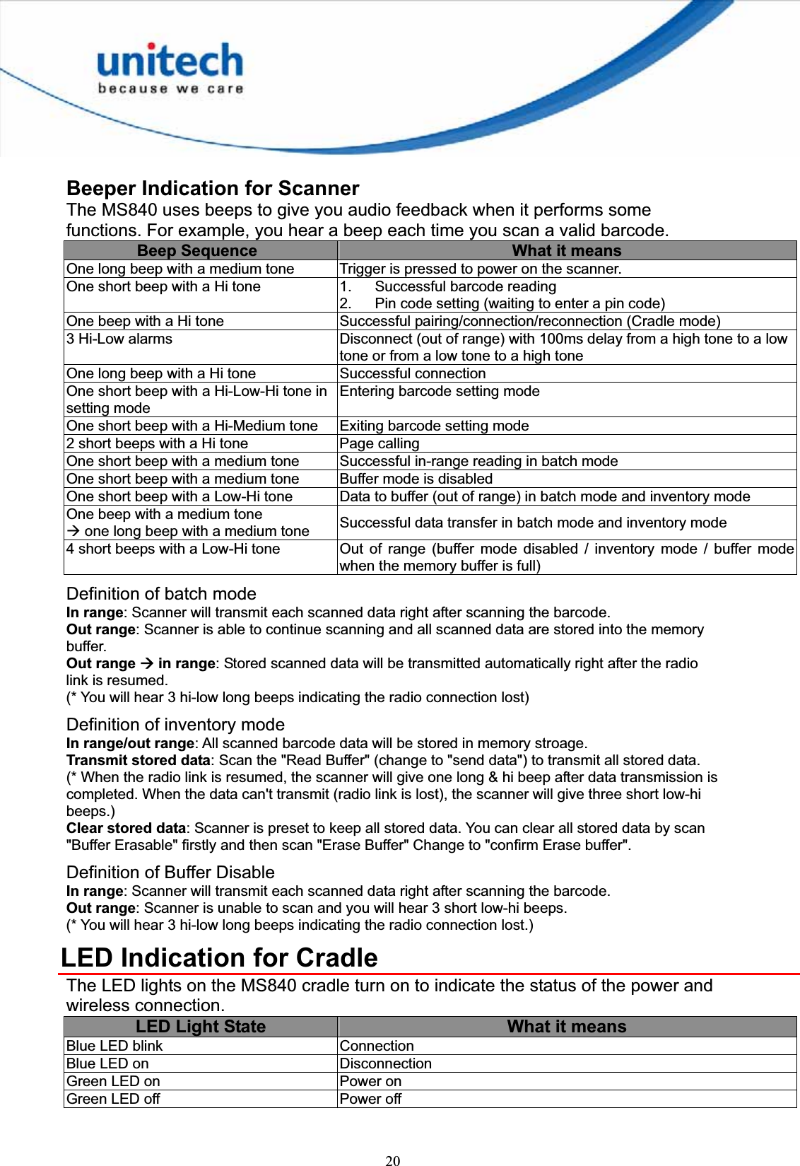
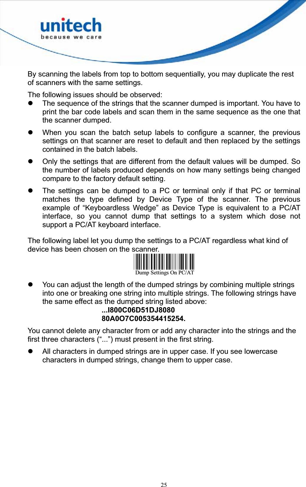
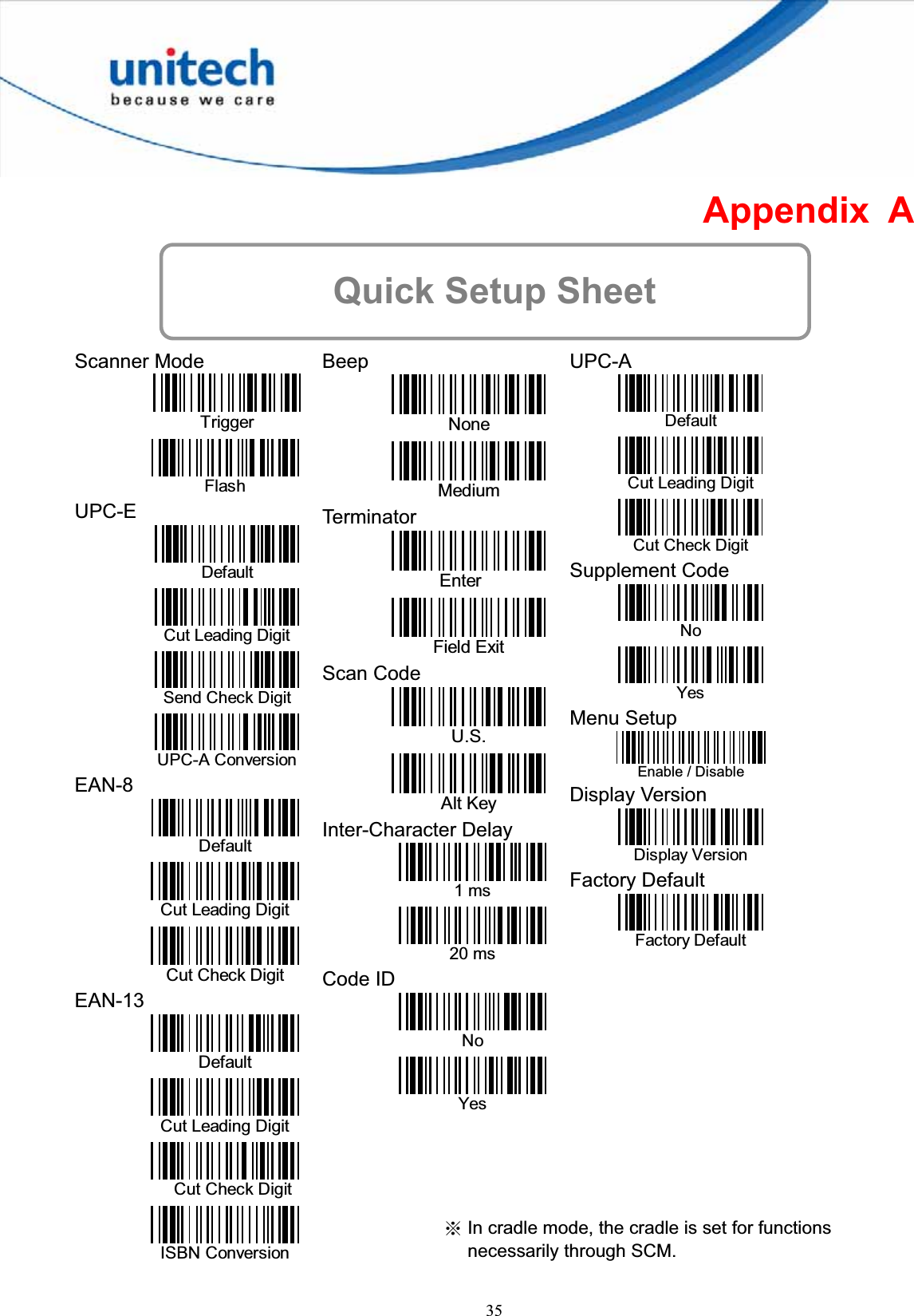
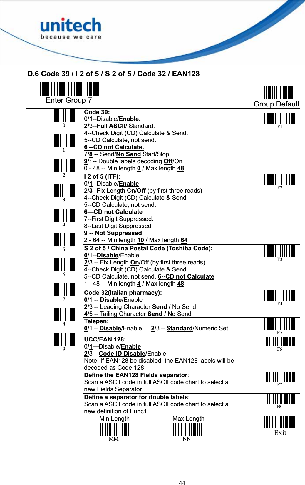
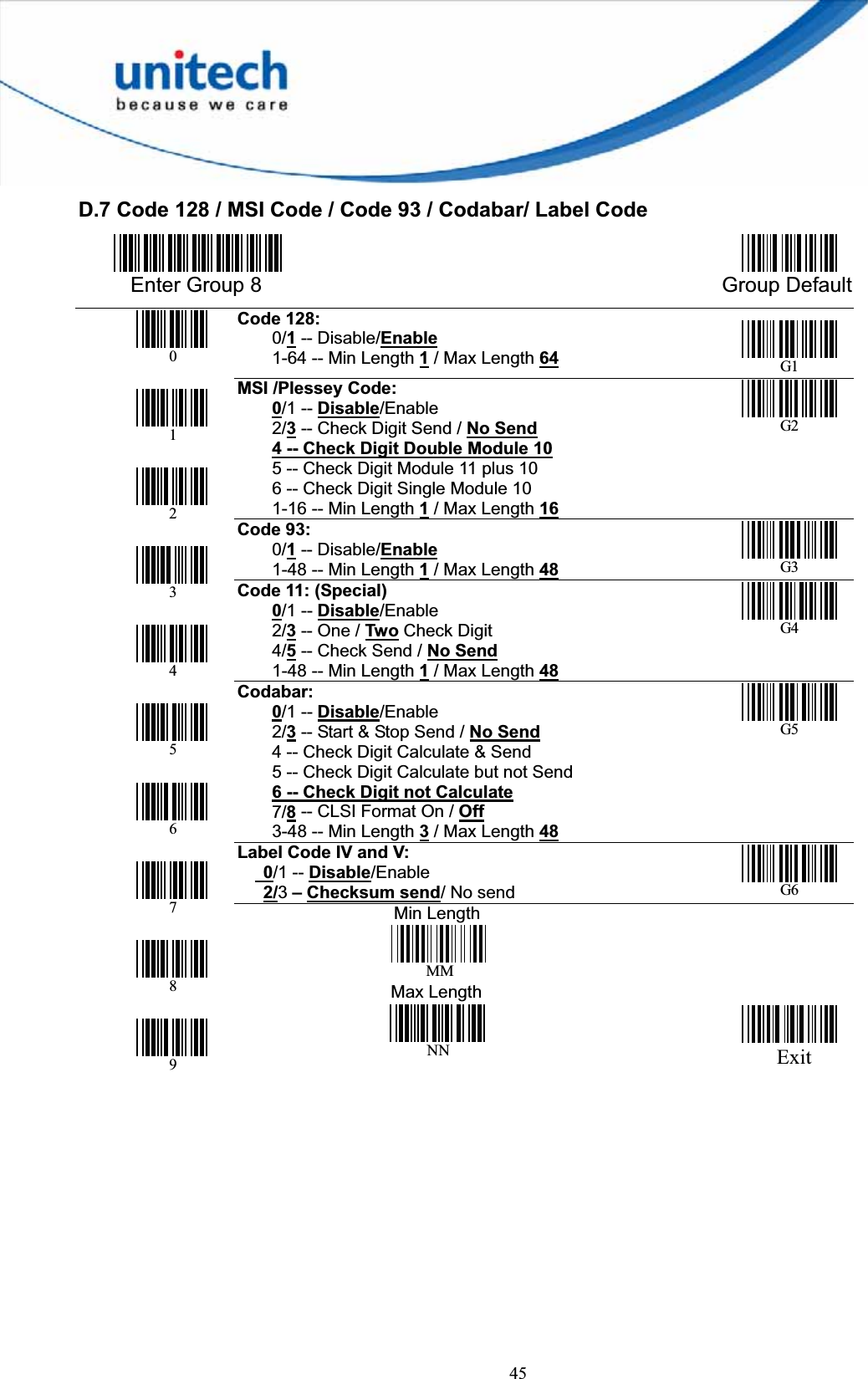
![22Barcode Length Setting The following example illustrates how to set Code 39 with a minimum length of 5 and a maximum length of 20. * Scan “Enter Group 7”. * Scan “F1” to select Code 39. * Scan “MIN LENGTH” to enter minimum length setting. * Scan “0” and “5” to select length 5. * Scan “MIN LENGTH” to end minimum length setting. * Scan “MAX LENGTH” to enter maximum length setting. * Scan “2” and “0” to select length 20. * Scan “MAX LENGTH” to end maximum length setting. * Scan “Exit” to end setup. Code ID Setting Each barcode symbology supported by the scanner has a default ID character defined below. If you don’t know what the label that you’re scanning is, you may use this feature to identify. Symbology Pre-DefinedUPC-A A UPC-E E EAN-13 F EAN-8 FF I 2 of 5 IS 2 of 5 HCode 39 MCodabar N Code 93 LCode 128 KUCC/EAN128 ]C1 MSI O Code 32 TDelta Code DPlessey Code PLabel Code IV,V B China Postal Code C Those ID characters can be redefined through setup menu. The following example shows how to set Code 93 with ID ‘O’ and Code 128 without ID: * Scan “Enter Group 5”. * Scan “D2” to select Code ID. * Scan “1” for "Enable". * Scan “D3” to define IDs. * Scan “0” and “9” for selecting Code 93. * Scan “O” from Full ASCII Table for new ID. * Scan “0” and "8" to select Code 128.](https://usermanual.wiki/Unitech-Electronics/MS84XG/User-Guide-2004494-Page-30.png)
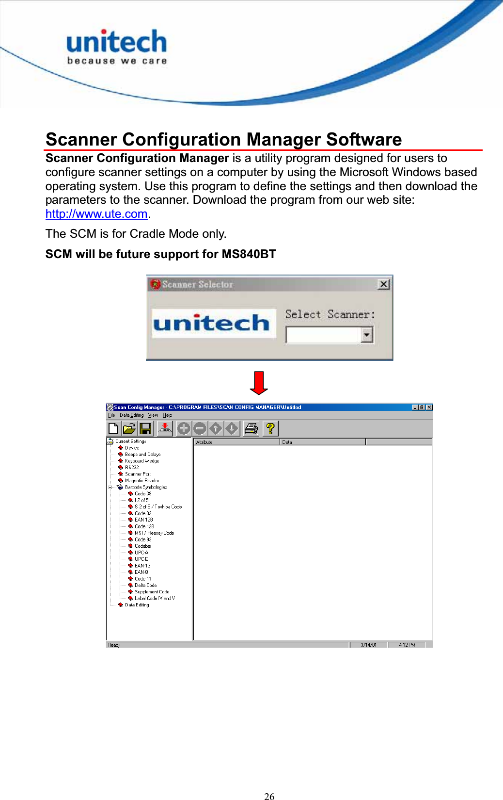
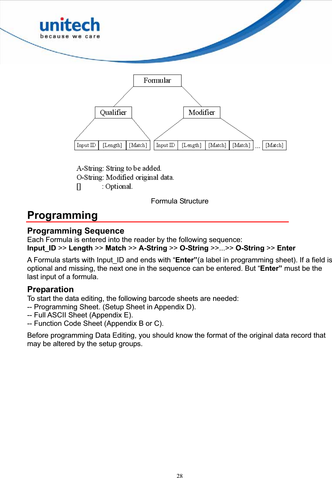
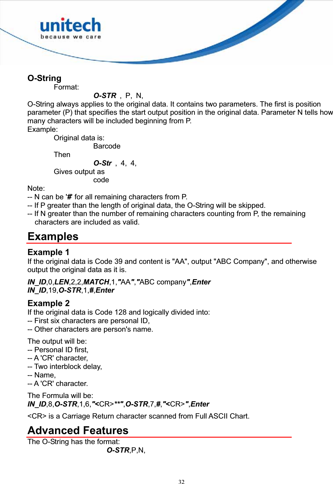
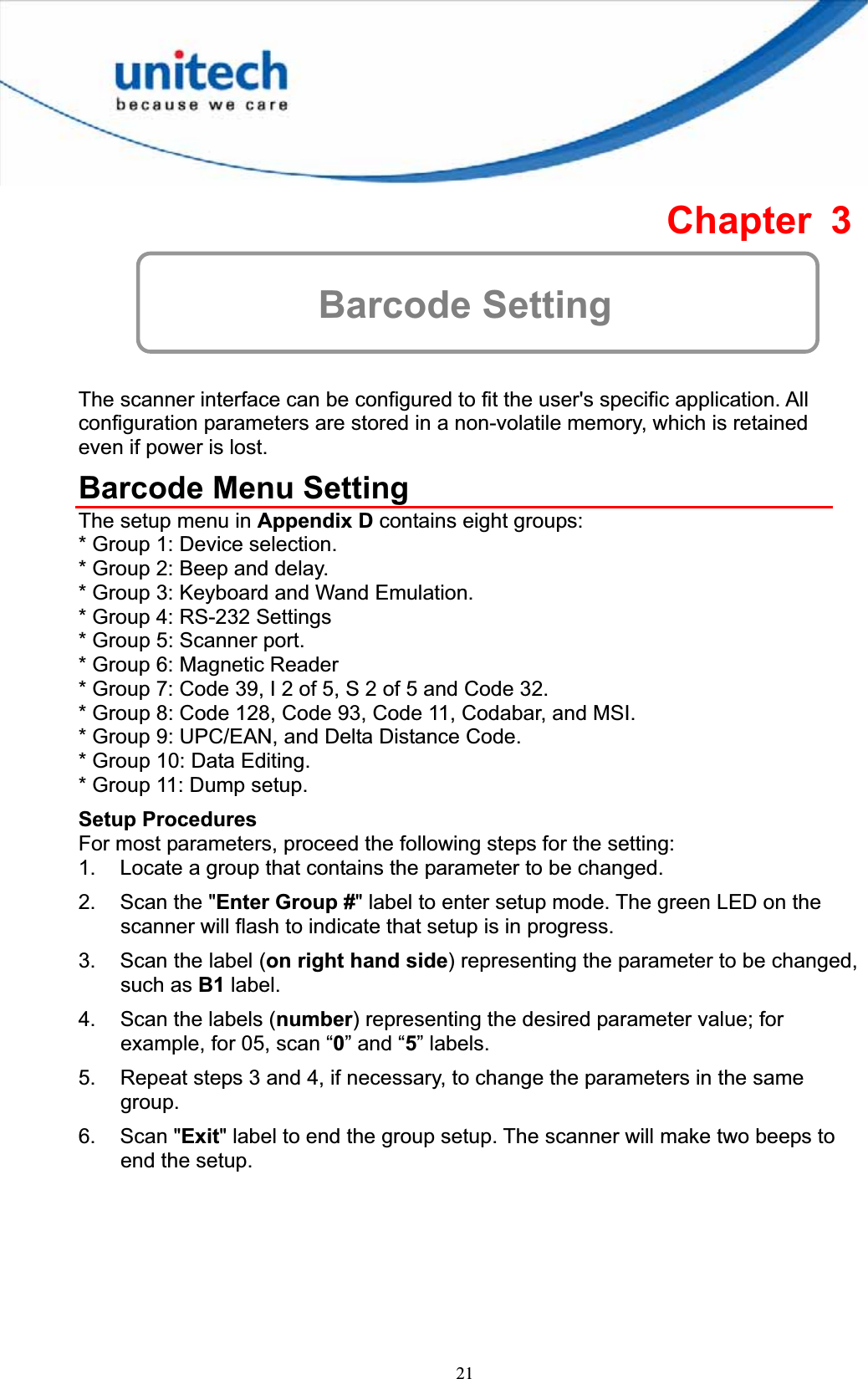
![33Both parameters of O-String mentioned above are numbers. But both parameters can be specified as strings. If N is a string, it becomes a position and the meaning of O-String will be "Output from position P to position N". If P is defined as: "ab...ik"a, b, I, and k can be any character, the position will be evaluated as -- Start from the first position of the original string and search character 'a'. -- From the position next to 'a' in original data, search for 'b'. -- .... -- From the position next to 'i', search for k. -- If above searches are all found, the result of the parameter will be the position where 'k' is located.If N is a string, the position evaluation of N is the same as P except that the searching position is starting from P+1. For both P and N, if string is defined, a value can be added to or subtracted from the position. That following O-Strings: "ab...ik"+M,and"ab...ik"-M,are meaningful. M is an integer number. Example:Suppose the following is a message to be modified: %B012345678901234^ABEL/STEVE L MGR ^90010129999999? In this message: "%" is start sentinel. "012345678901234" is account number. "^" is a separator 6. "ABEL" is surname. "/" is a separator. "STEVE" is first name. "L" is initial. "MGR" is title "^" is a separator. "9001" is expiration date. "?" is end sentinel. The output sequence desired is: Surname, First Name [CR] Account Number [CR] Expiration Date [CR] The formula input will be: IN_ID,0,O-STR,"^"+1,"/"-1,",",O-STR,"/"+1,"<SP>"-1,"<CR>",O-STR,3,"^"-1,"<CR>",O-STR,"^^"+1,4,"<CR>",EnterHere <SP> is Space character and <CR> is Carriage Return character.](https://usermanual.wiki/Unitech-Electronics/MS84XG/User-Guide-2004494-Page-41.png)
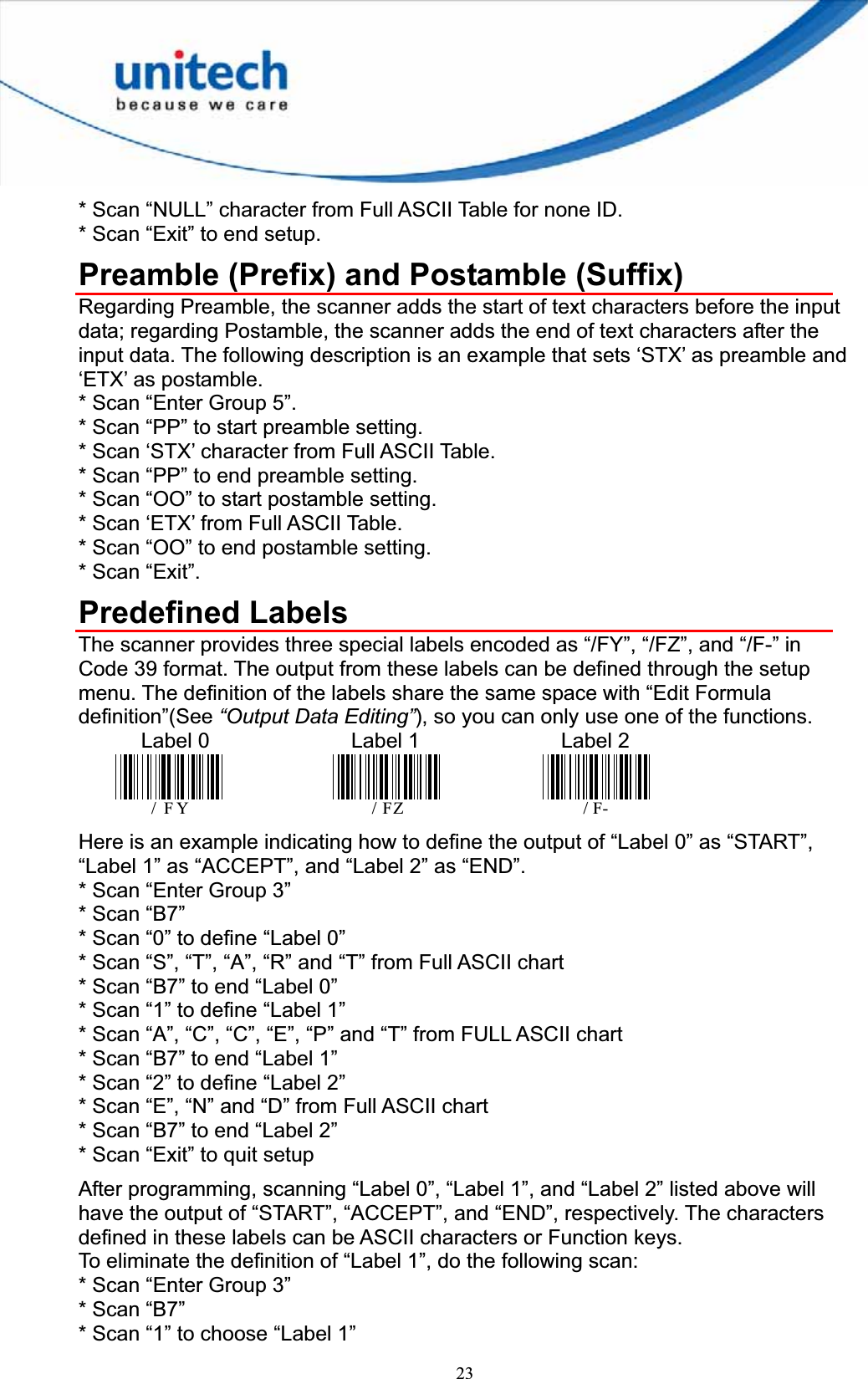
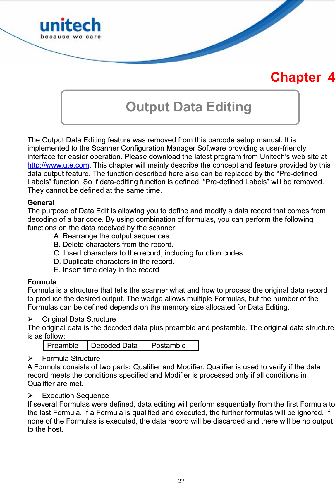
![34The output of above input will be ABEL,STEVE[CR] 012345678901234[CR] 9001[CR]](https://usermanual.wiki/Unitech-Electronics/MS84XG/User-Guide-2004494-Page-42.png)
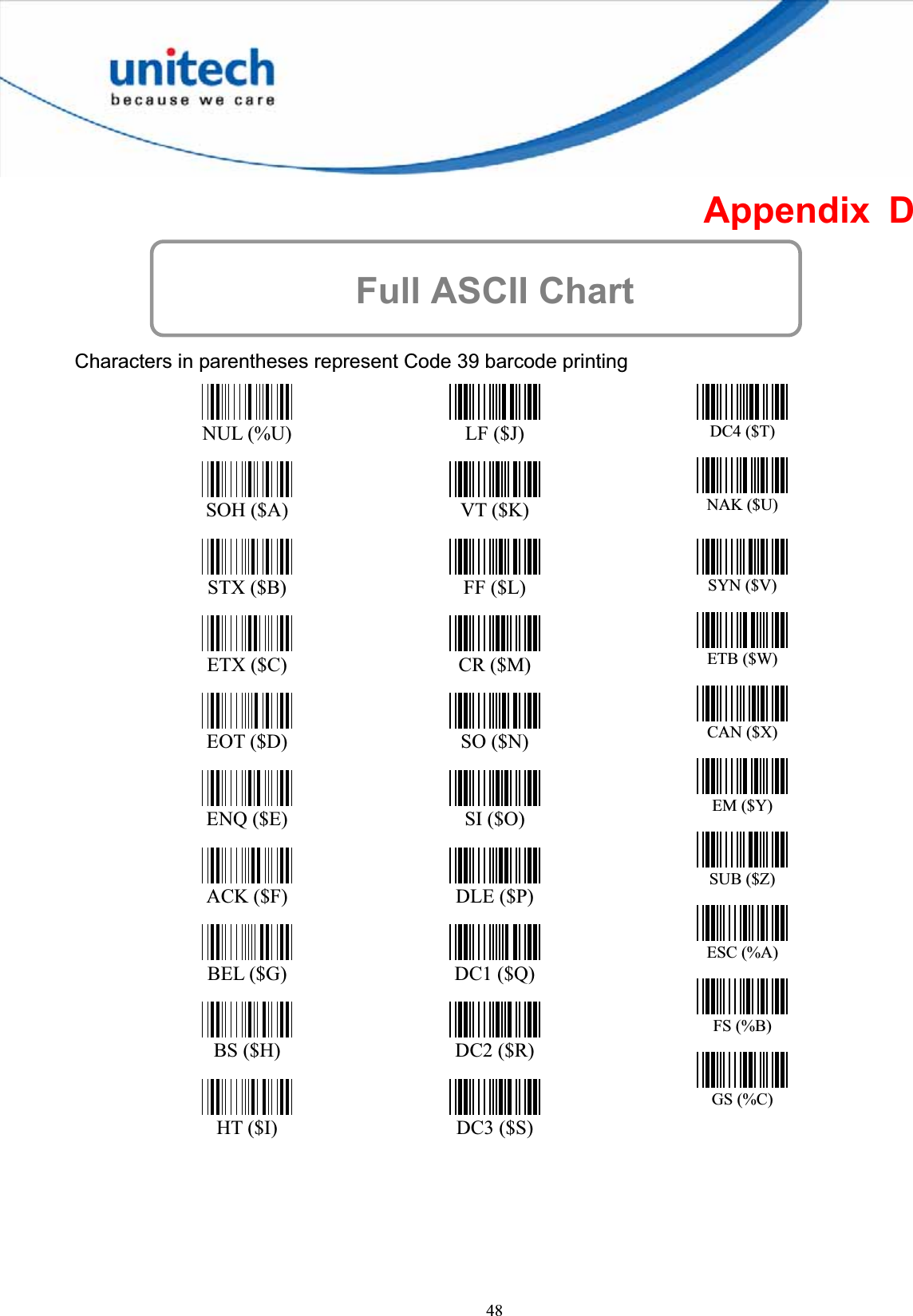
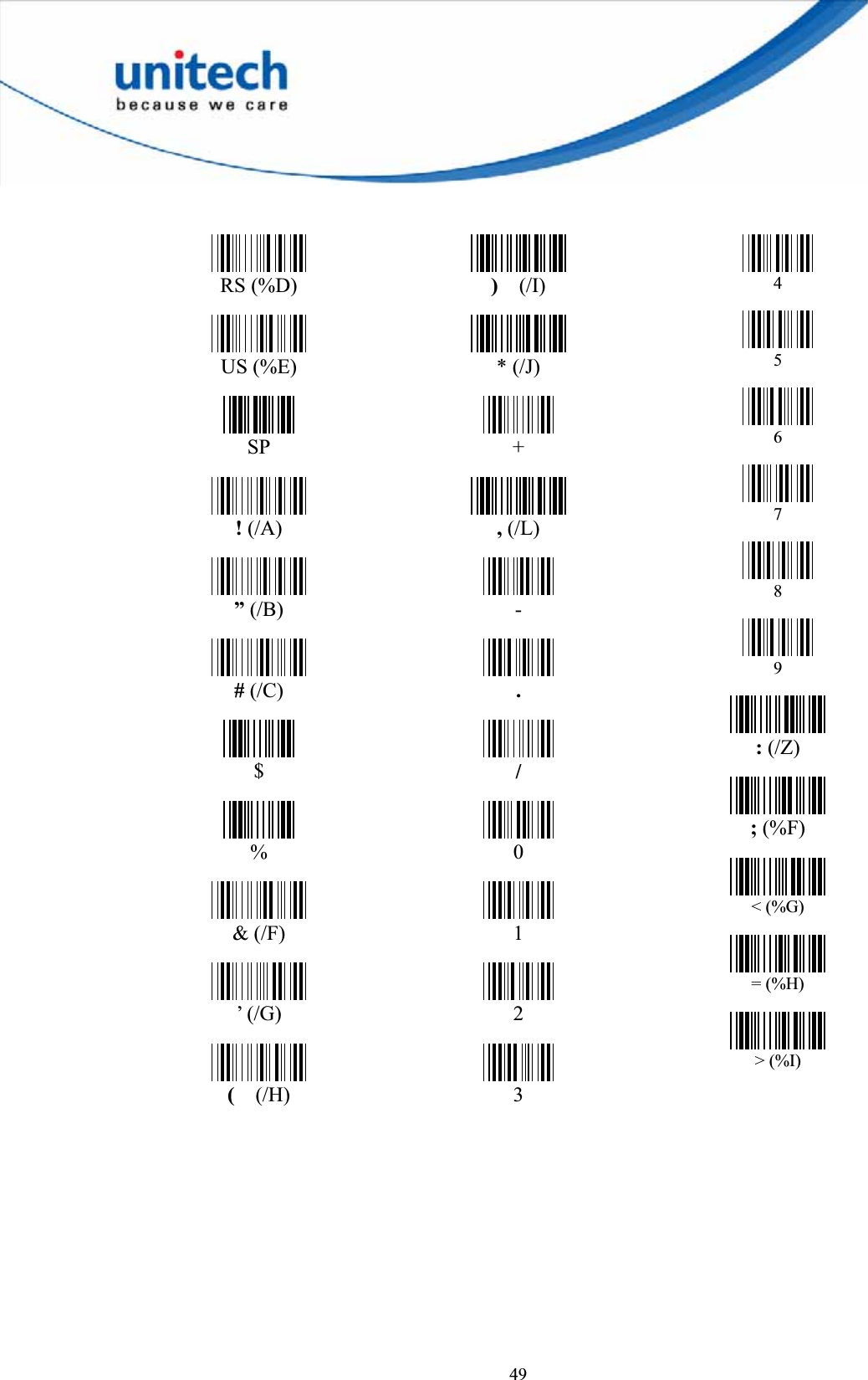
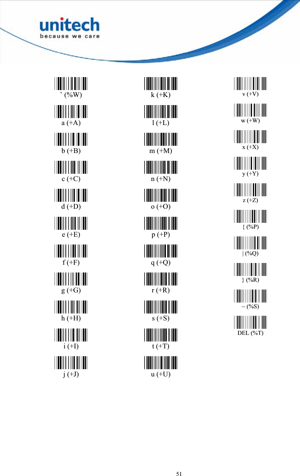
![50? (%J) @ (%V) ABCDEFGHIJKLMNOPQRSTUVWXYZ[ (%K) \ (%L) ] (%M) ^ (%N) _ (%O)](https://usermanual.wiki/Unitech-Electronics/MS84XG/User-Guide-2004494-Page-58.png)