Unitech Electronics MT18EM01 An Economy Versatile T&A; Terminal User Manual
Unitech Electronics Co., Ltd. An Economy Versatile T&A; Terminal
UserManual.wiki
>
Unitech Electronics
>
MT18EM01 User Manual
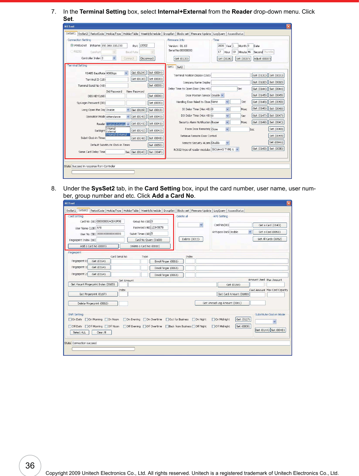
User manual
Navigation menu
Upload a User Manual
Namespaces
Wiki Guide
HTML
PDF
Info
Views
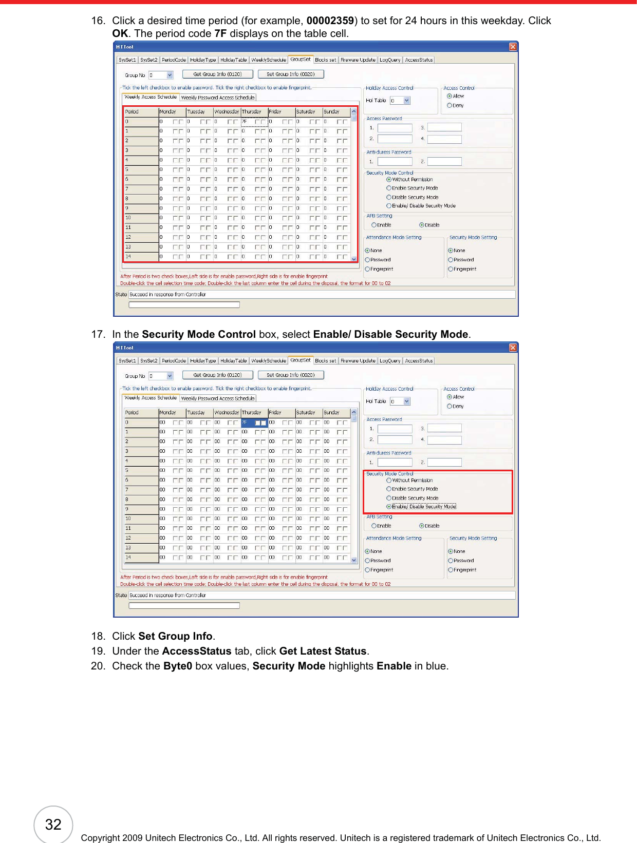
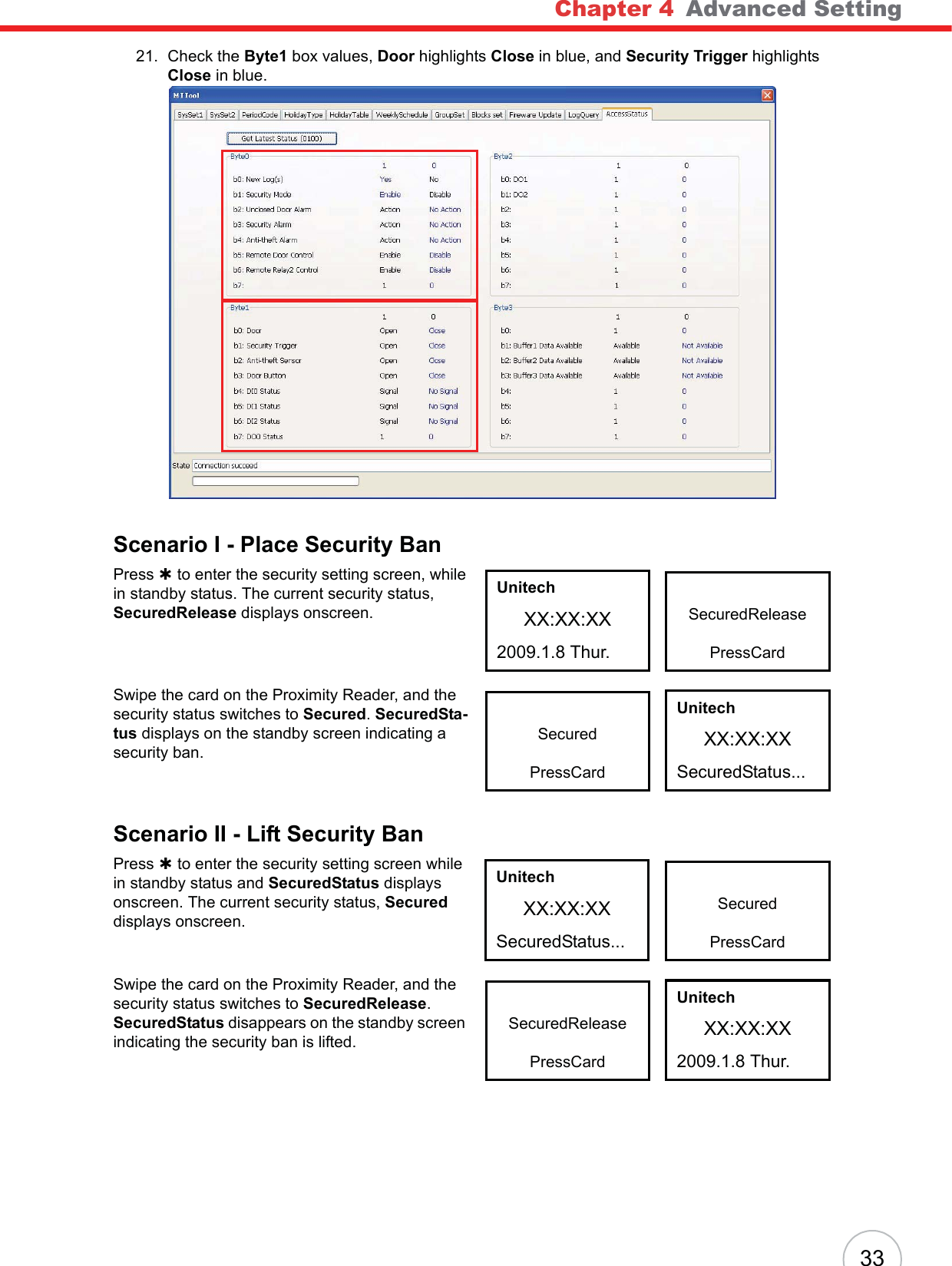
User Manual
Discussion / Help
Navigation

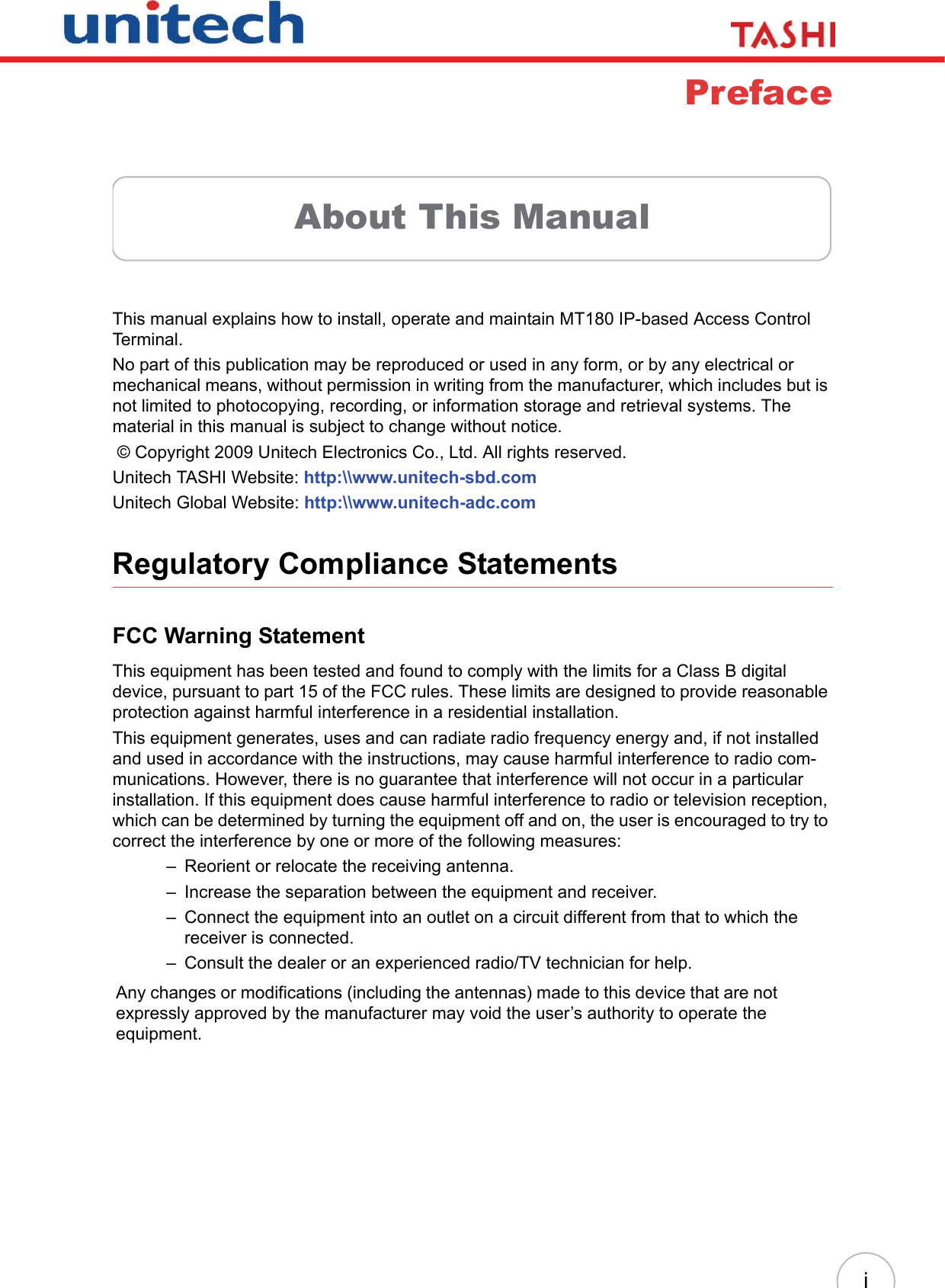

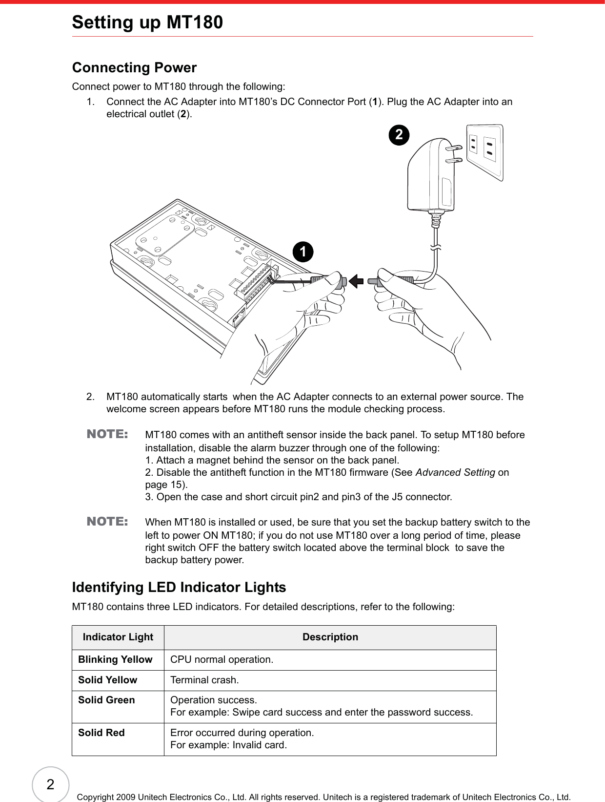
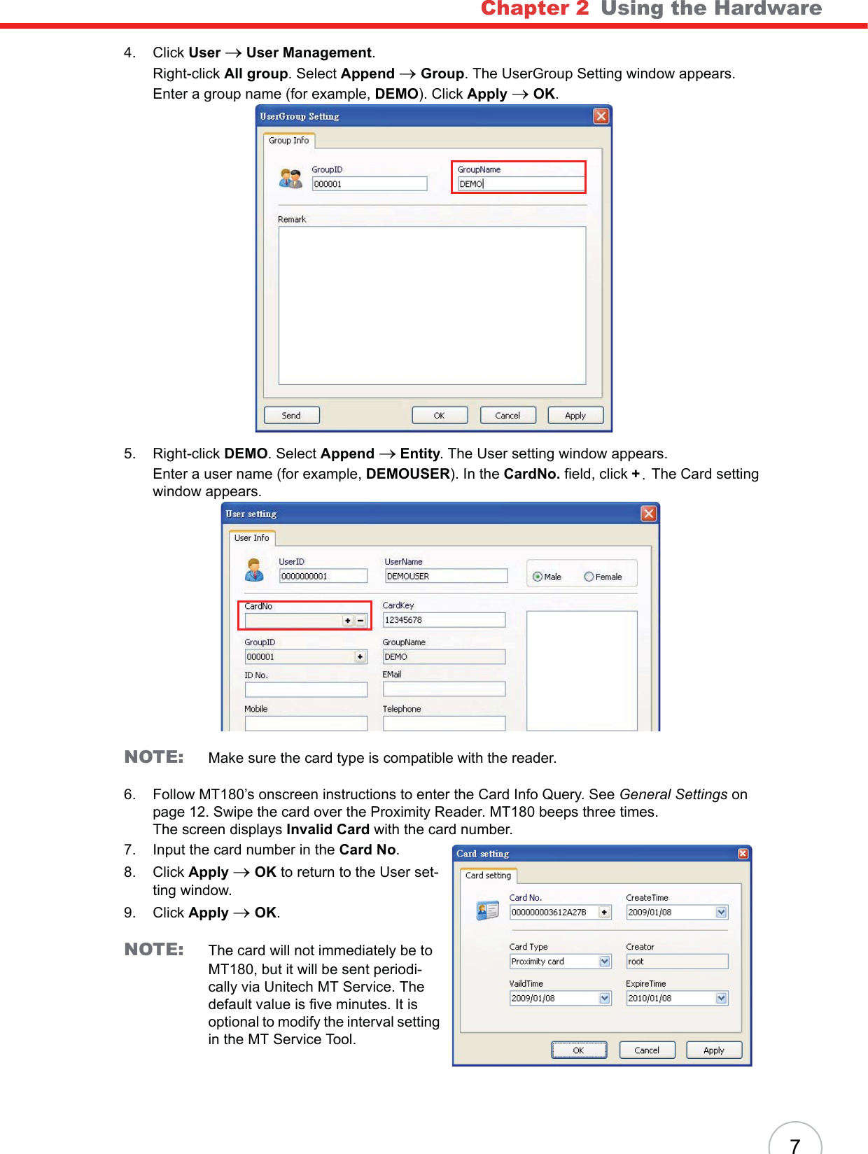
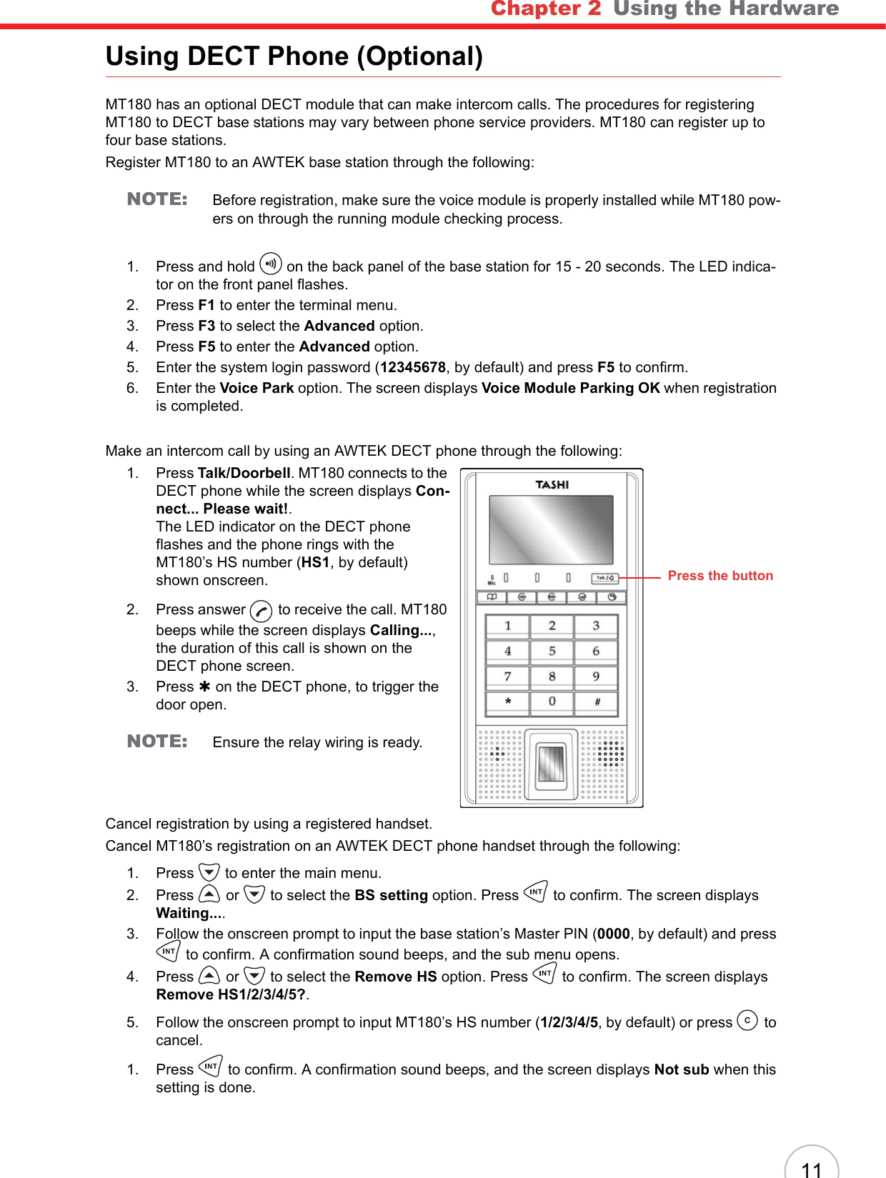
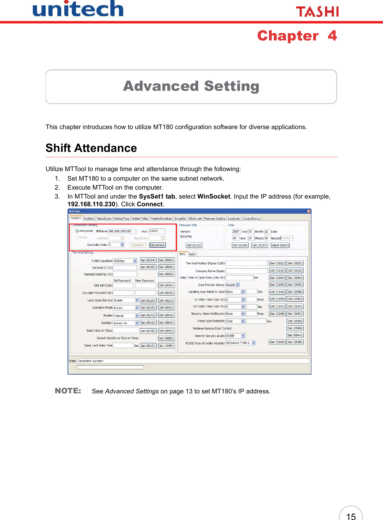
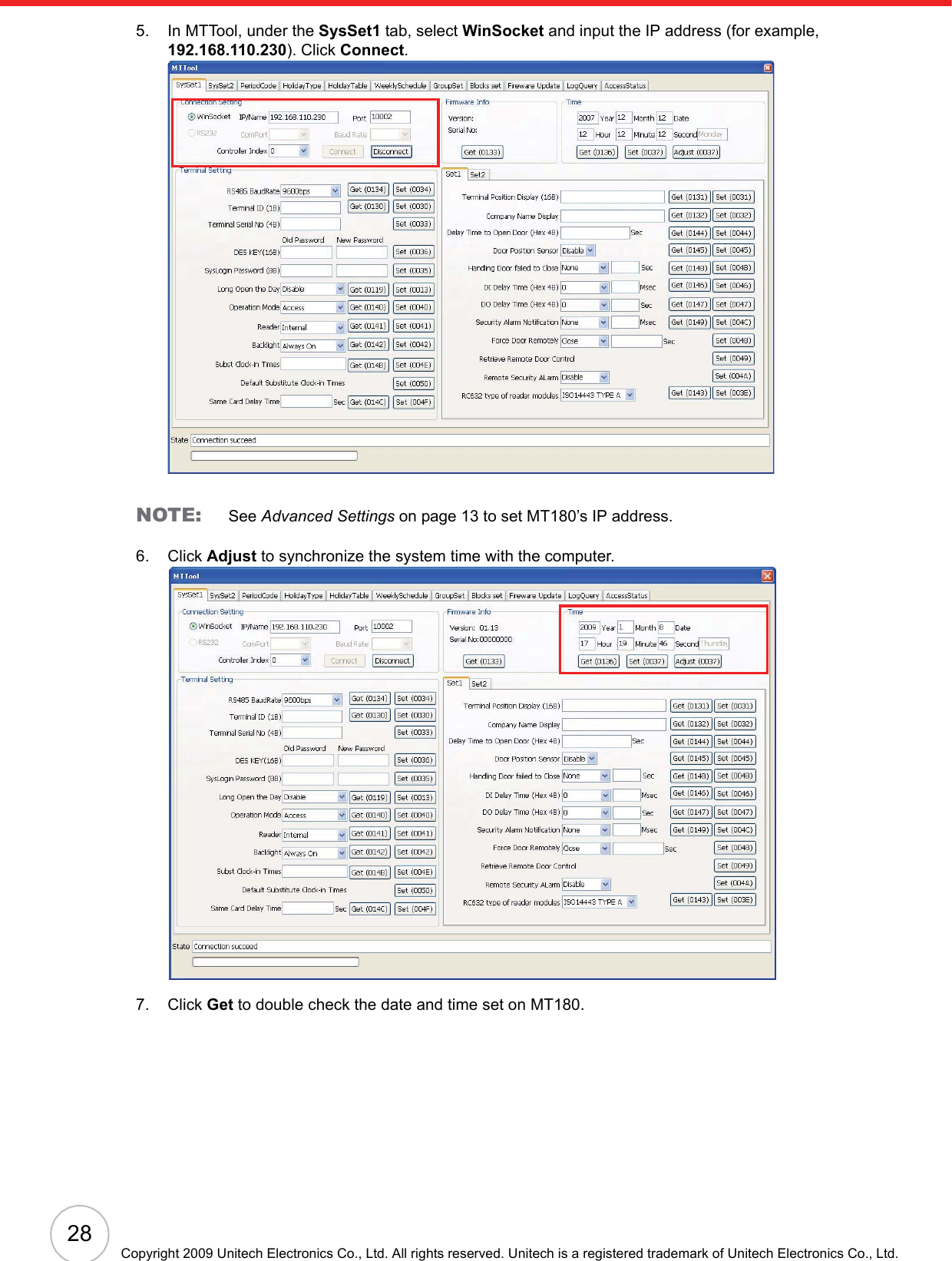
![5Chapter 2Using the HardwareUsing the KeypadMT180 contains five function keys and 12 numeric keys.MT180’s key functions are described in the following:After powering on MT180, the standby screen displays the company name, system time and date, which are configurable by pressing F1 button to enter the menu options.While in standby status, press # during the password access period, and then follow the onscreen prompt to input 2-digit group number and a 4-digit group access password to open the door.In Access+Attendance Mode, press F2 or F3 to switch into Attendance Mode. Press F2 or F3 to choose the work shift and swipe an ID card to clock in. To use the substitute clock in, press any key and follow the onscreen prompt to input a user clock in number.Key Main FunctionMenu.[F1]: Open menu options.Clock in.[F2]: Move upward through menu items.Clock out.[F3]: Move downward through menu items.Break in.[F4]: Returns to the previous menu item.Break out.[F5]: Enters a menu item or confirms a setting.TalkMicFunctionKeysNumericKeys](https://usermanual.wiki/Unitech-Electronics/MT18EM01/User-Guide-1141754-Page-11.png)
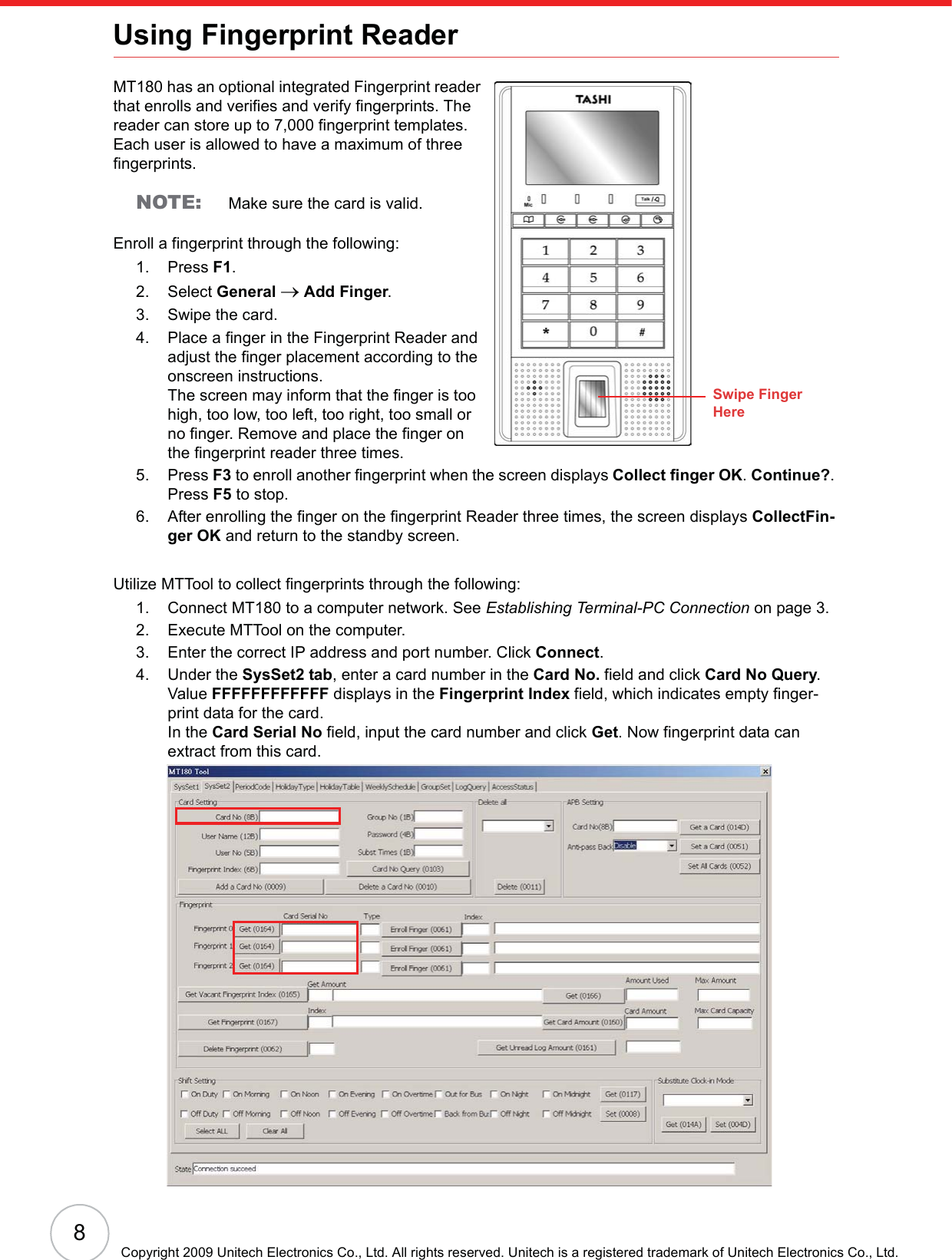
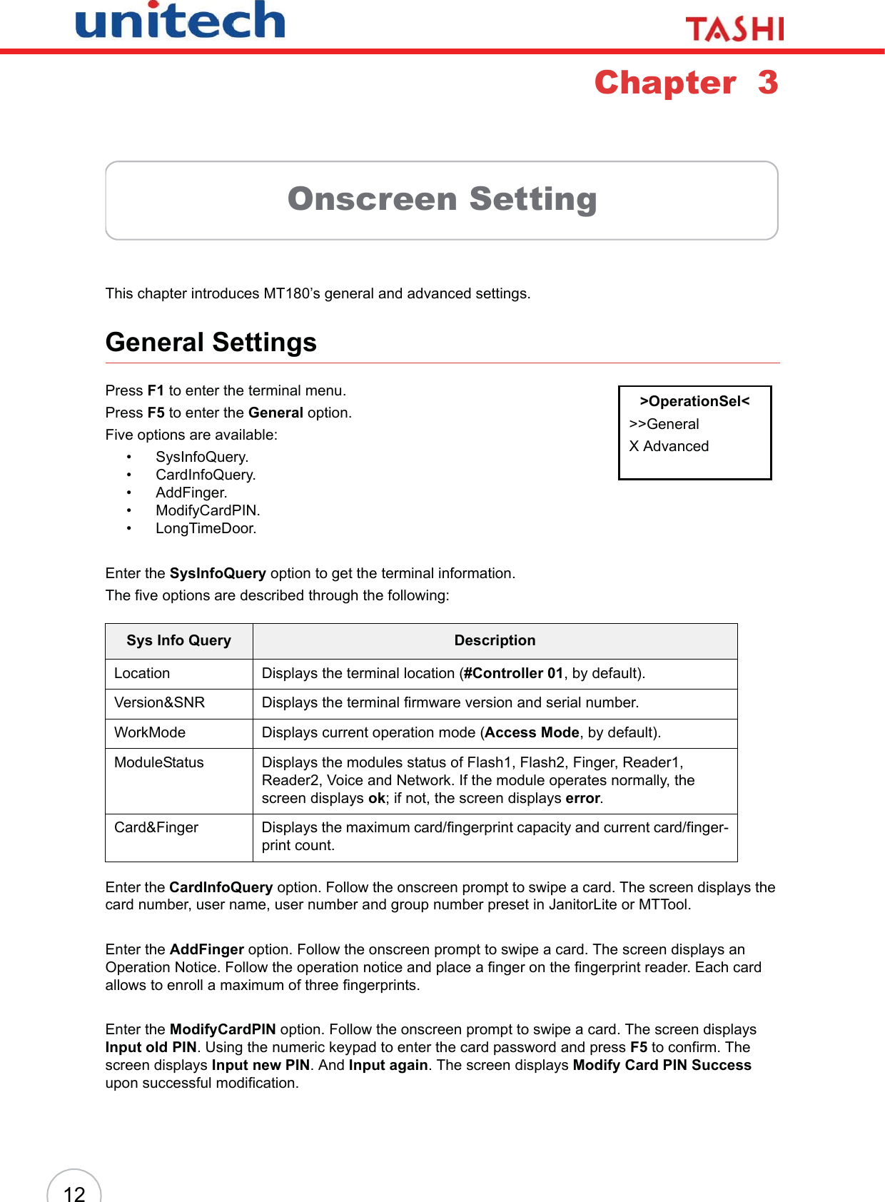
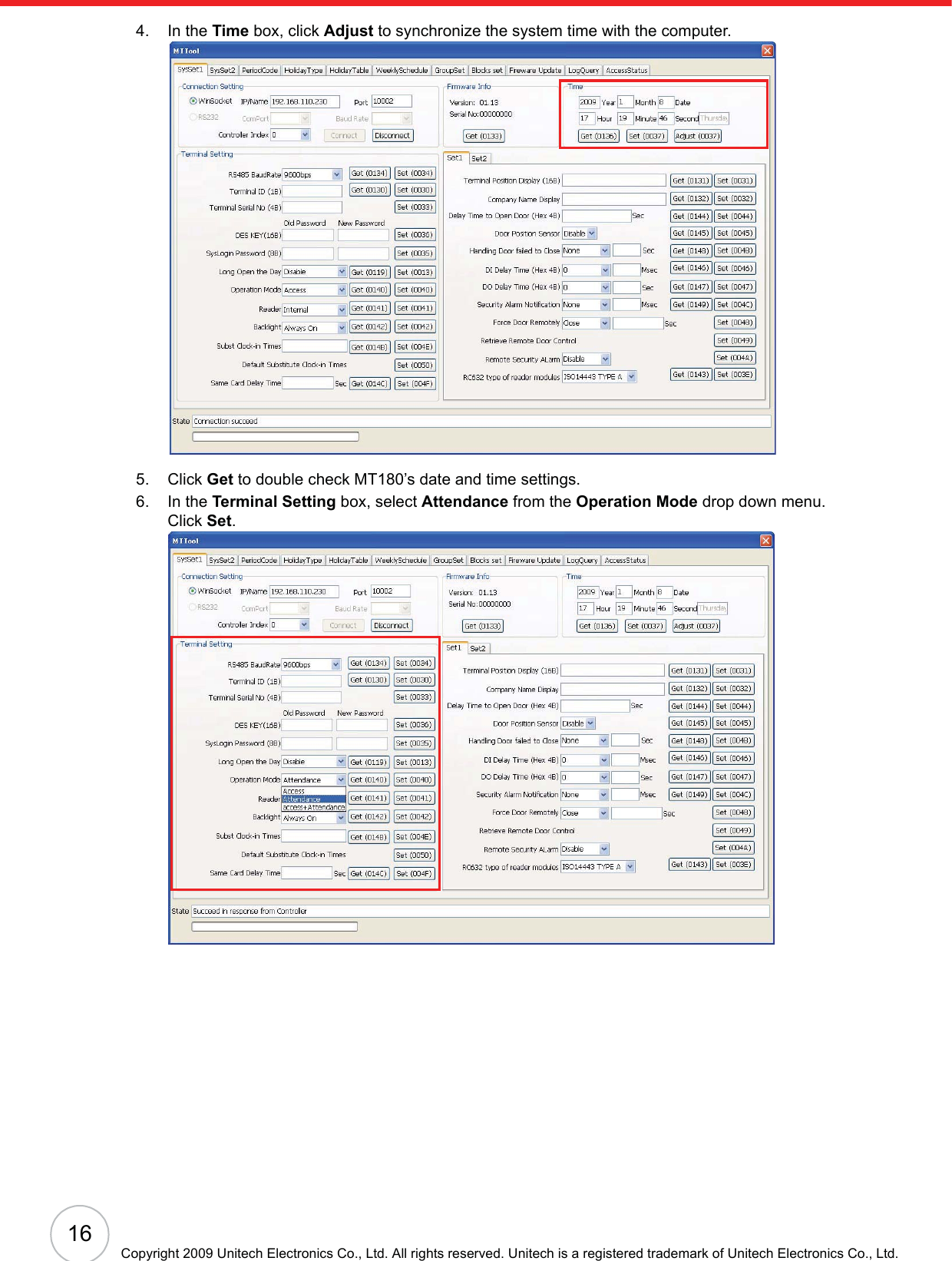
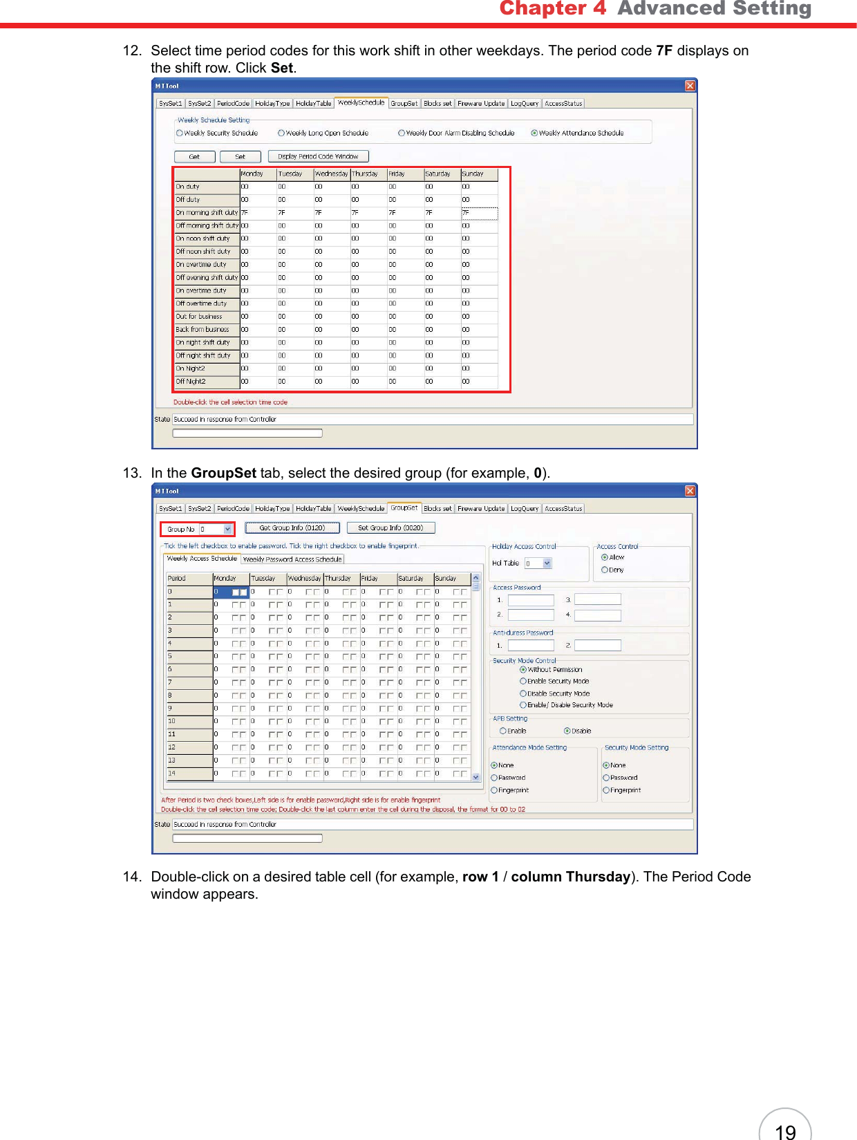
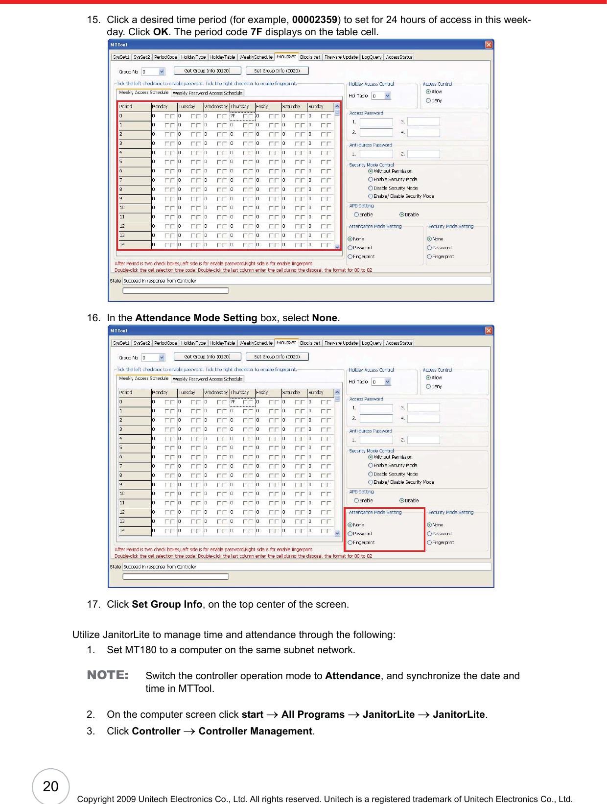
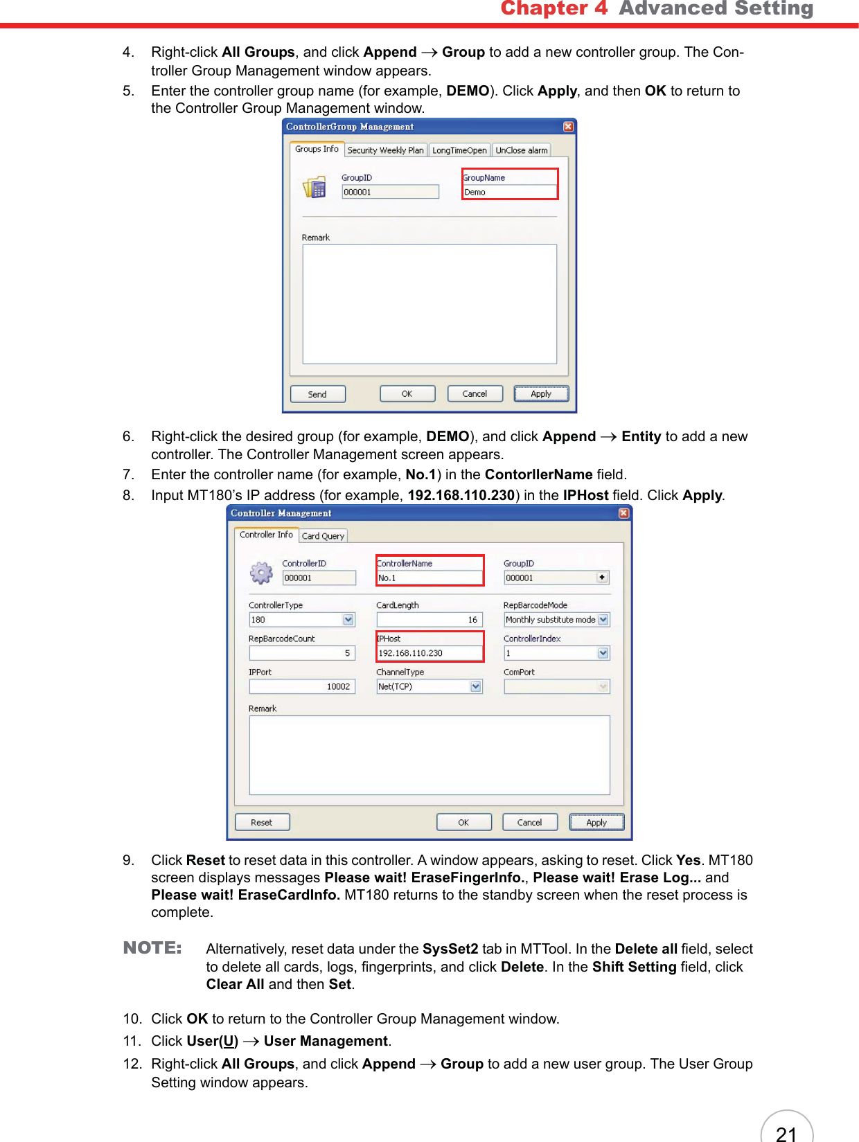
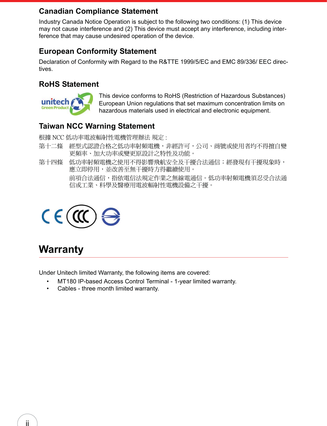
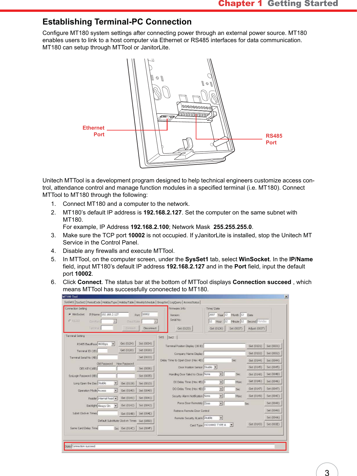
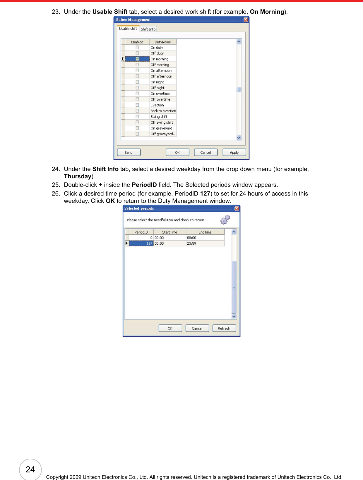
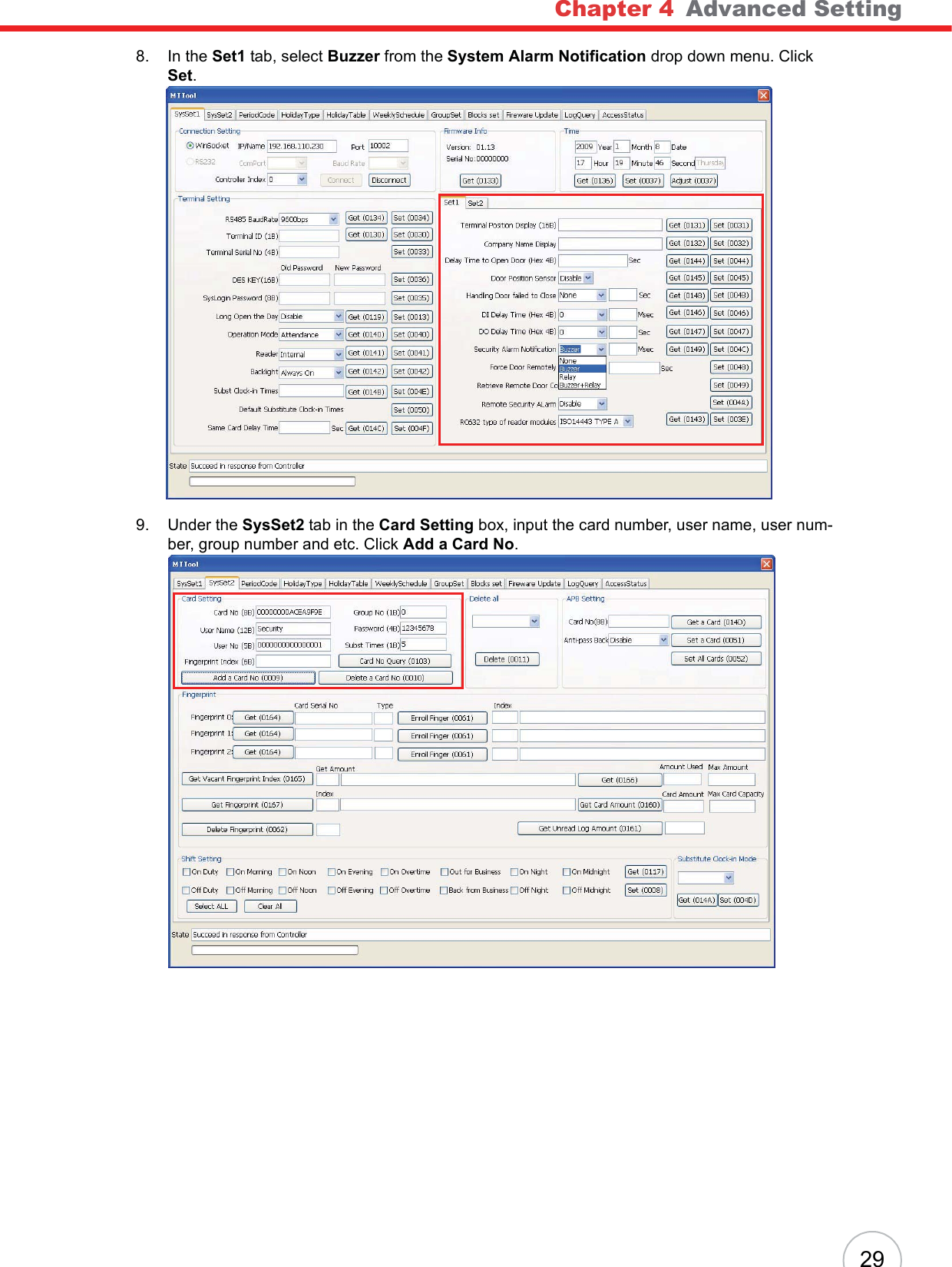
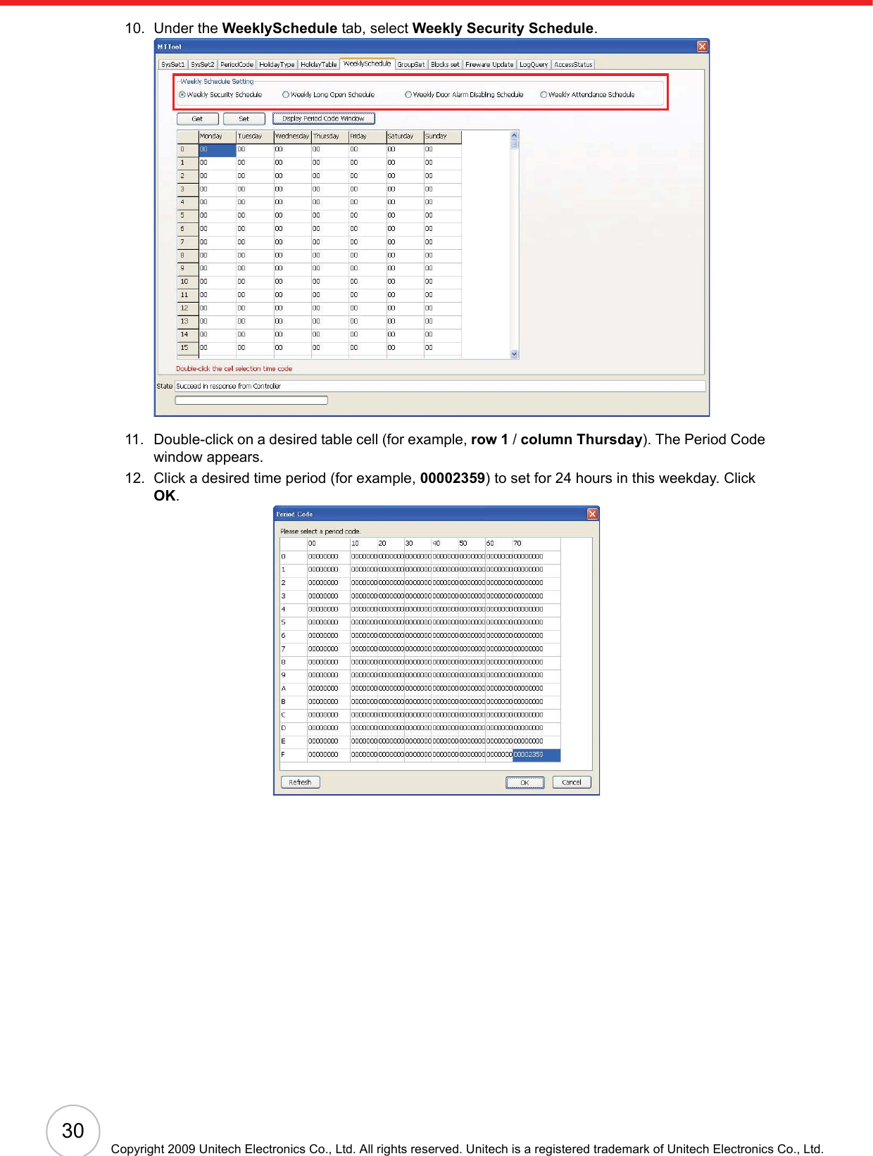
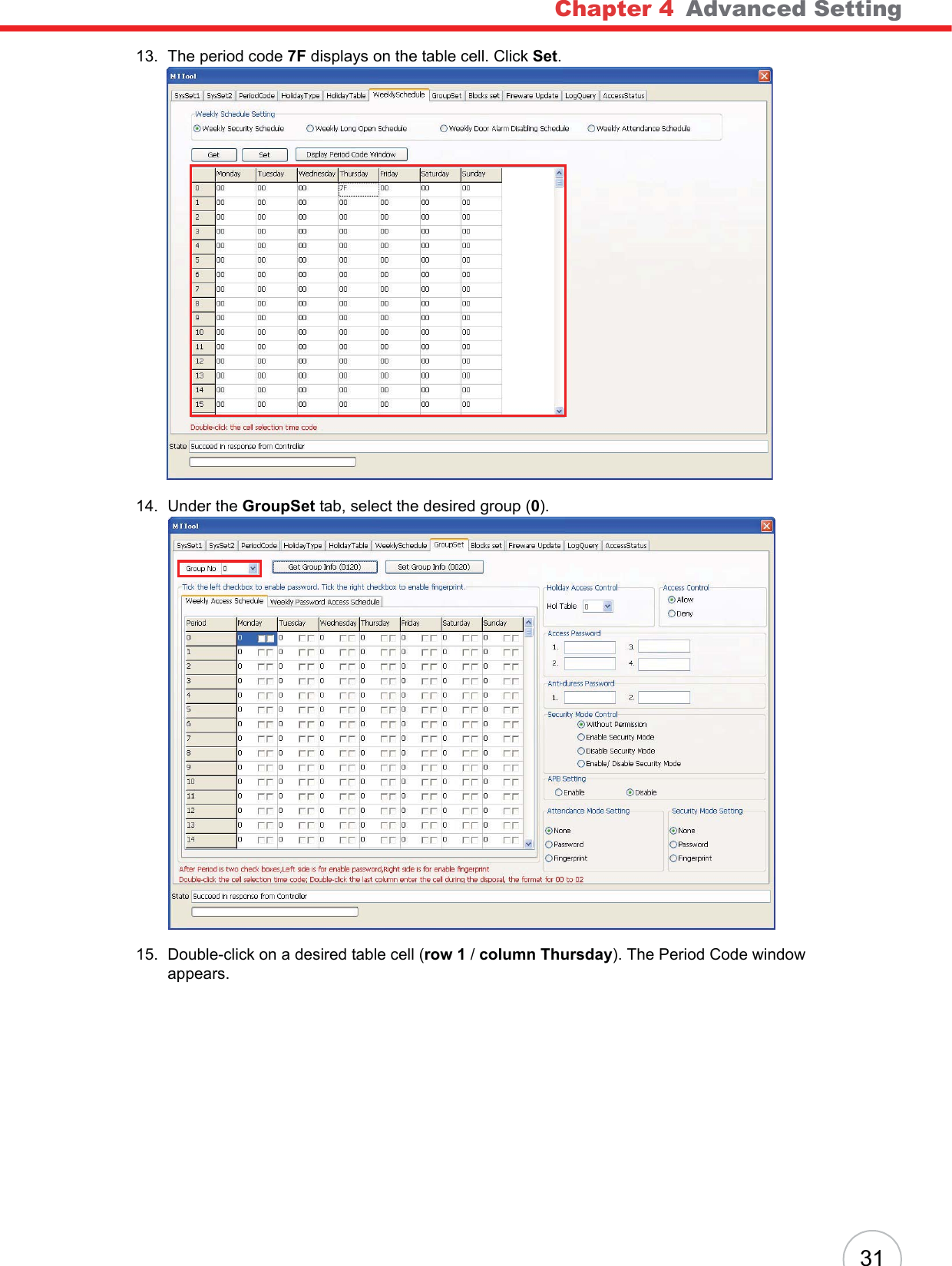
![Chapter 4 Advanced Setting2317. Input the card number in the Card No. field. Click Apply, and then OK to return to the User set-ting window.NOTE: See General Settings on page 12 to acquire the card number.18. Click OK to return to the User Group Setting window.19. Click Permit(P)o Permit Management.20. Select the desired user group (for example, DEMO), and click Setting on the toolbar. The Selected Controllers window appears.21. Select the desired controllers (for example, No.1 DEMO), and click OK to return to the Janitor-Lite - [Permit Management] window.22. Click Attendance o Duty Management.](https://usermanual.wiki/Unitech-Electronics/MT18EM01/User-Guide-1141754-Page-29.png)
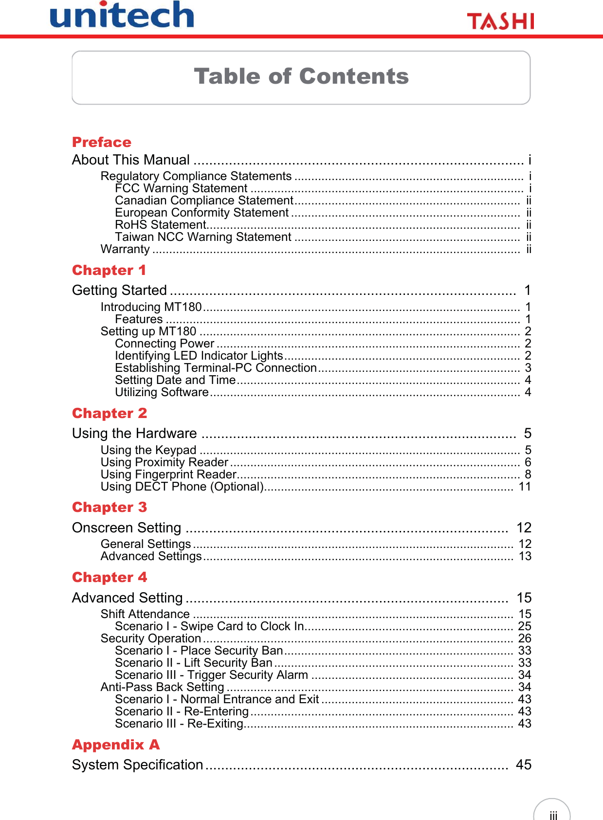
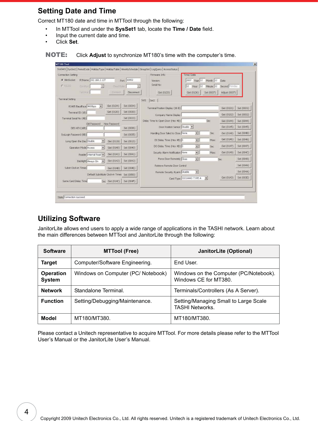
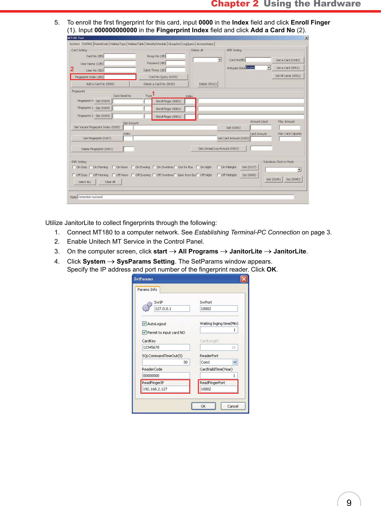
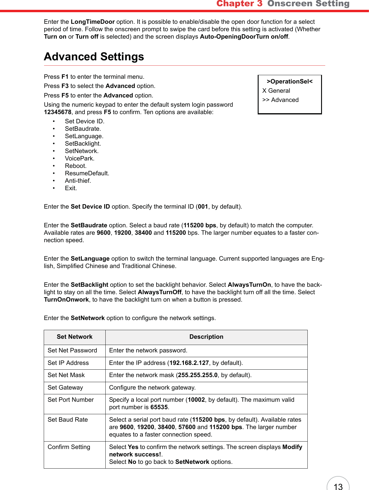
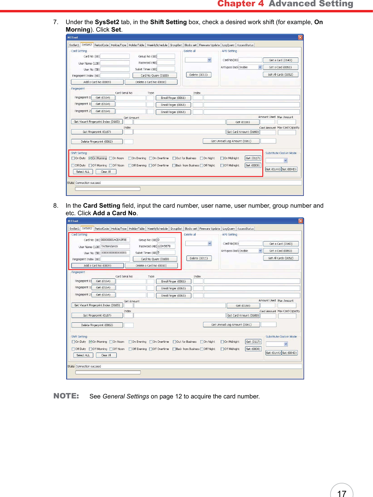
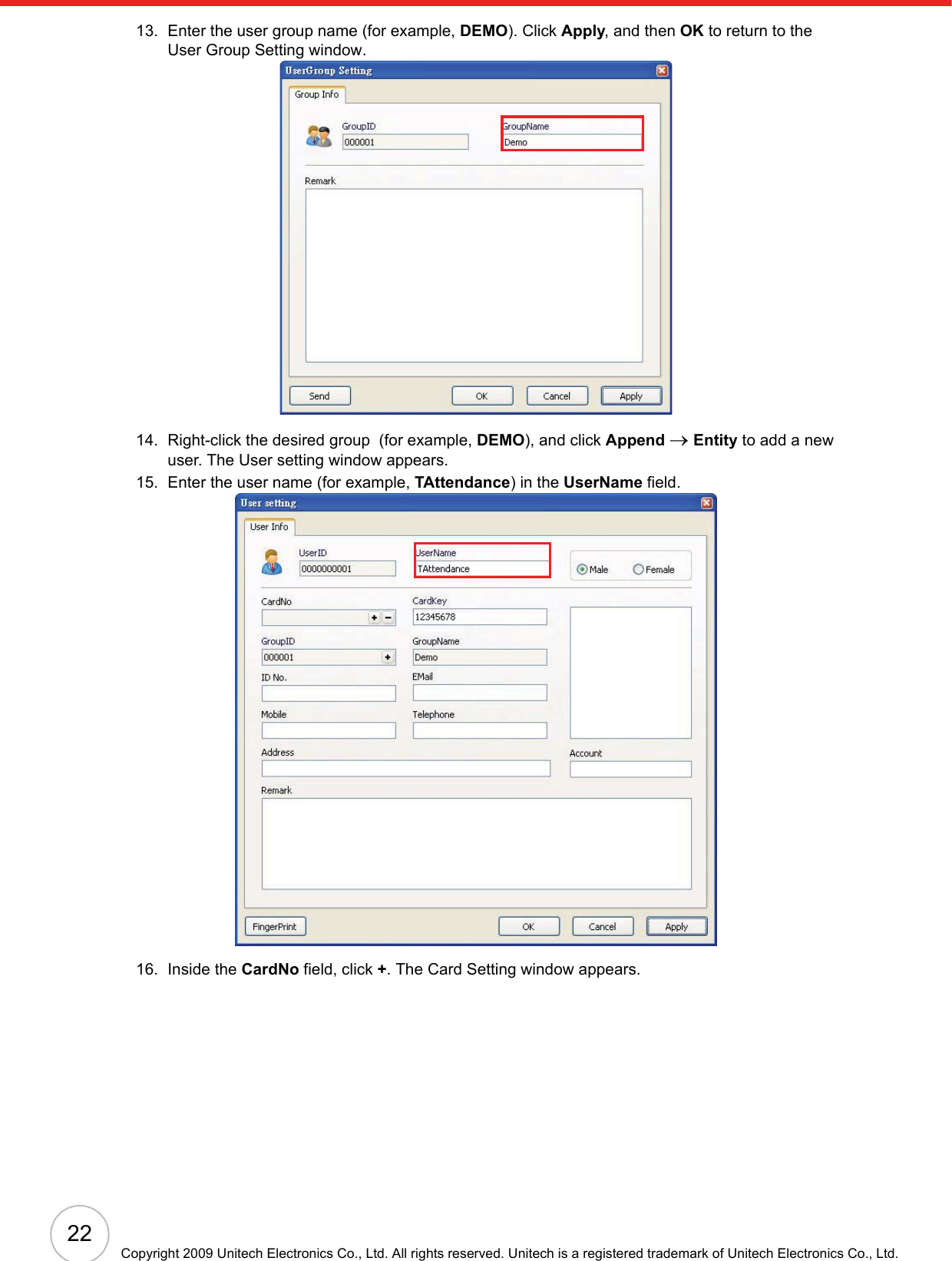
![40Copyright 2009 Unitech Electronics Co., Ltd. All rights reserved. Unitech is a registered trademark of Unitech Electronics Co., Ltd.13. Right-click All Groups, and click Append o Group to add a new user group. The UserGroup Setting window appears.14. In the GroupName field, enter the user group name (Demo). Click Apply oOK to return to the JanitorLite - [Users Management] window.15. Right-click the desired group (Demo), and click Append oEntity to add a new user. The User Setting window appears.16. In the UserName field, enter the user name (for example, APB).17. Inside the CardNo field, click +. The Card setting window appears.](https://usermanual.wiki/Unitech-Electronics/MT18EM01/User-Guide-1141754-Page-46.png)
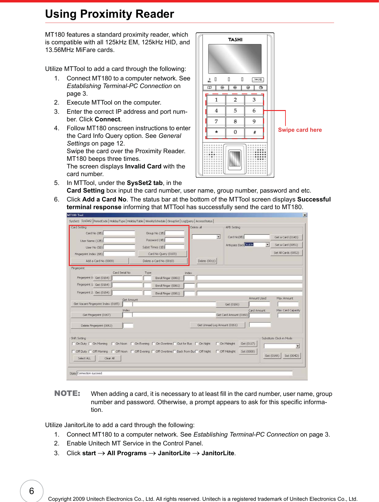
![Chapter 4 Advanced Setting4118. Input the card number in the Card No. field. Click Apply oOK to return to the User setting window.NOTE: See General Settings on page 12 to acquire the card number.19. Click OK to return to the JanitorLite - [Users Management] window.20. Click Permit(P)o Permit Management.21. Select the desired user group (Demo), and click Setting on the toolbar. The Selected Control-lers window appears.22. Select the desired controllers (MT180 and Demo), and click OK to return to the JanitorLite - [Permit Management] window.23. Double-click the desired user group (Demo). The UserGroup Setting window appears.](https://usermanual.wiki/Unitech-Electronics/MT18EM01/User-Guide-1141754-Page-47.png)
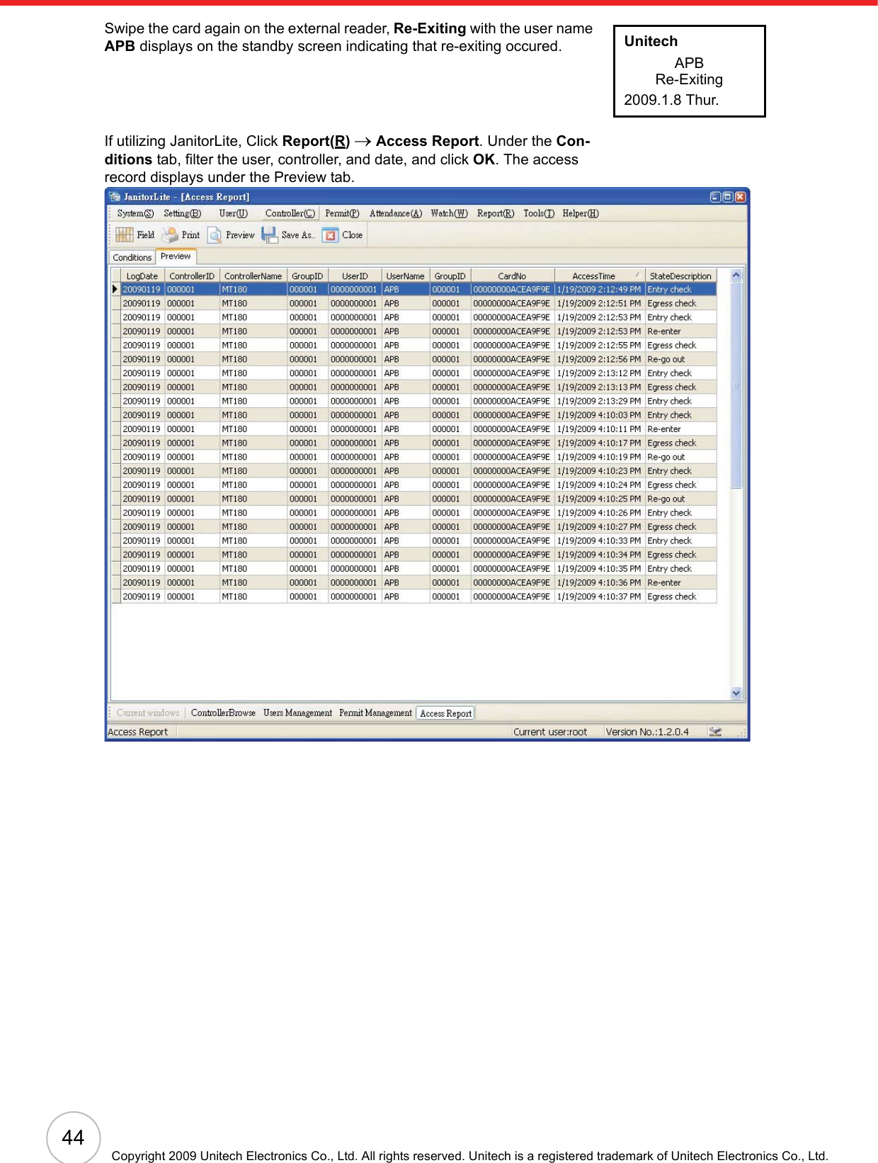
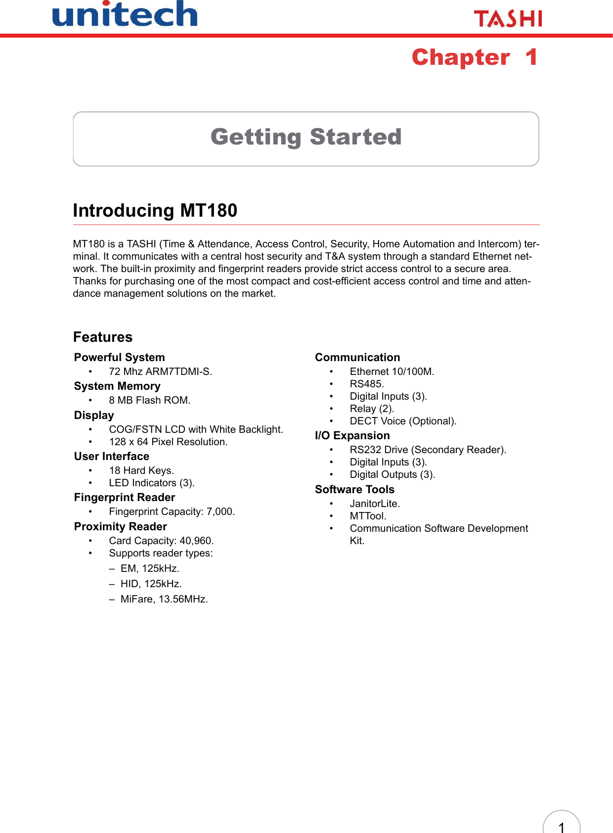
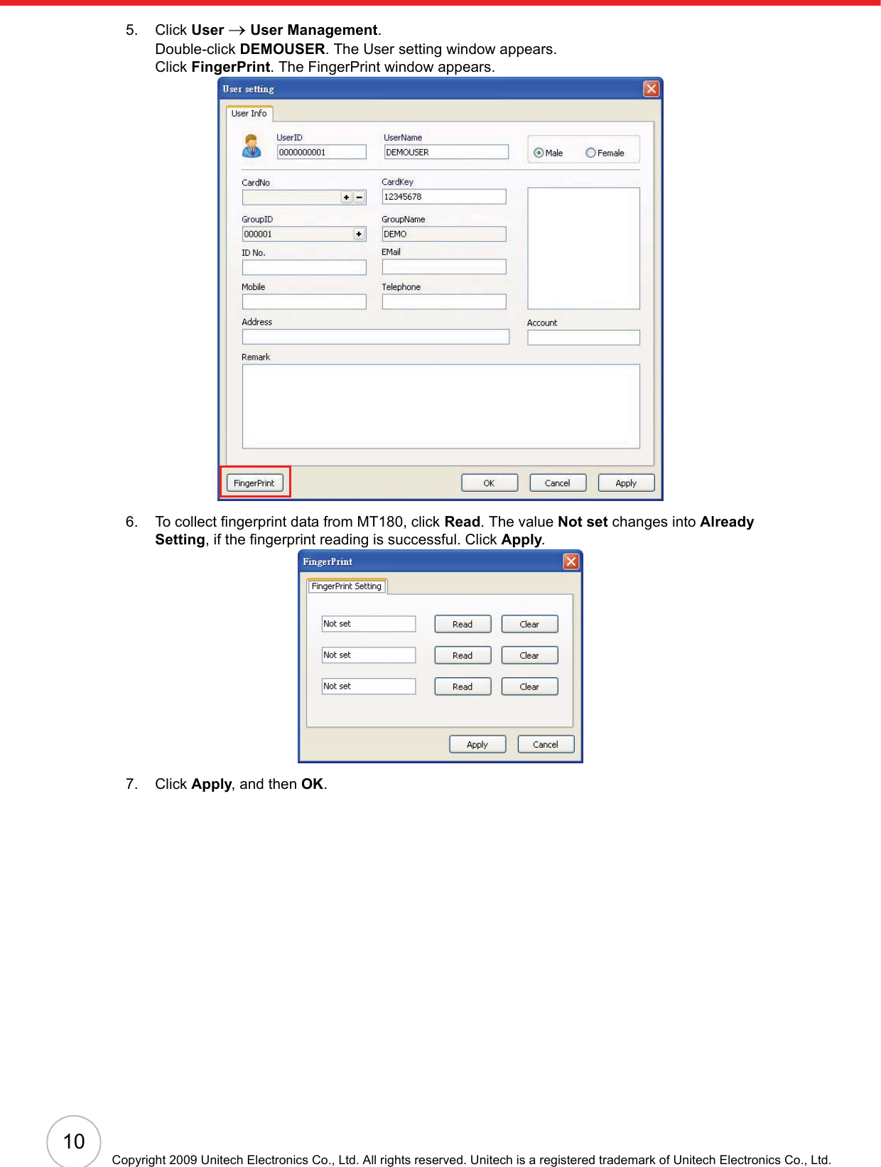
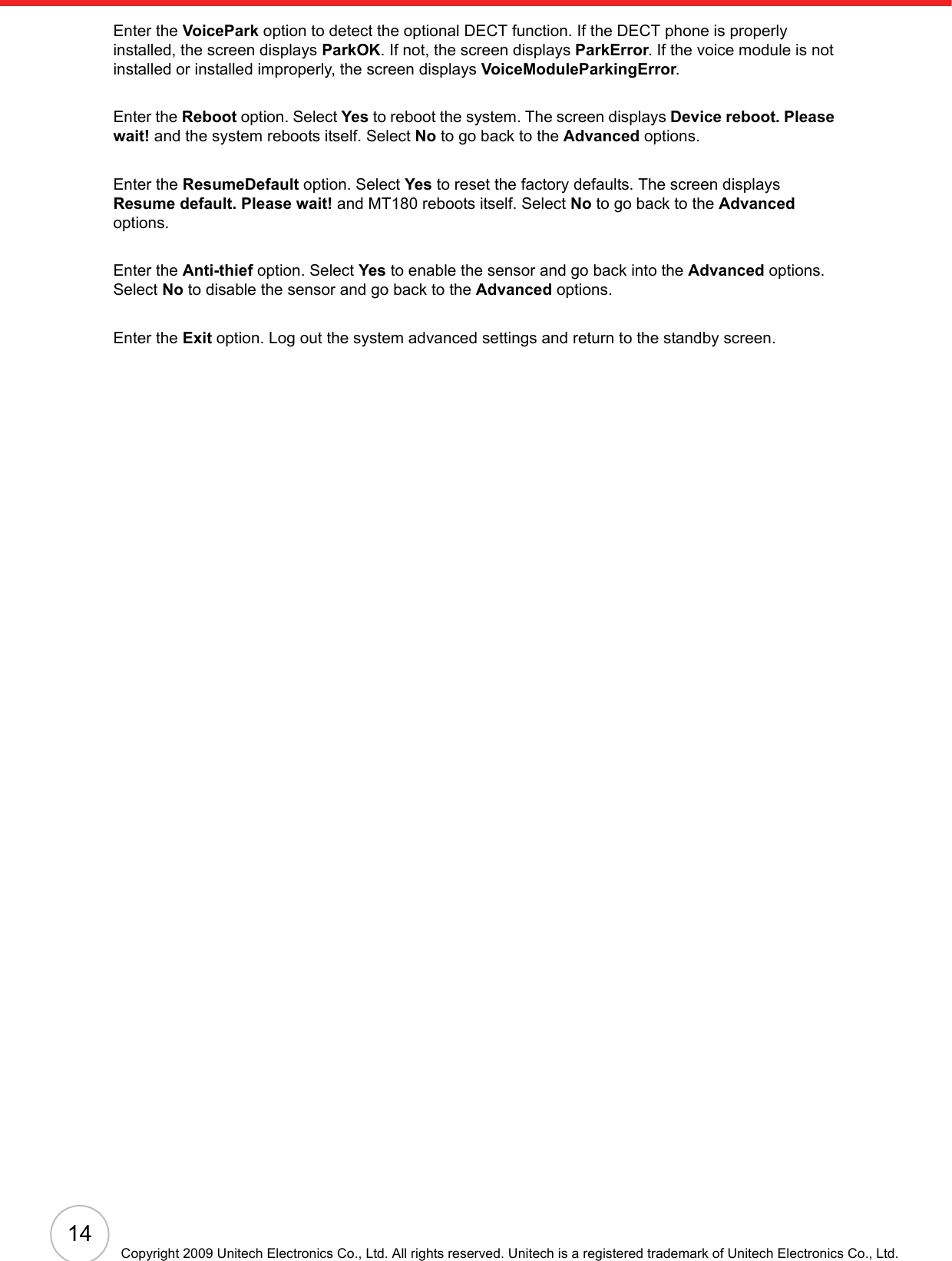
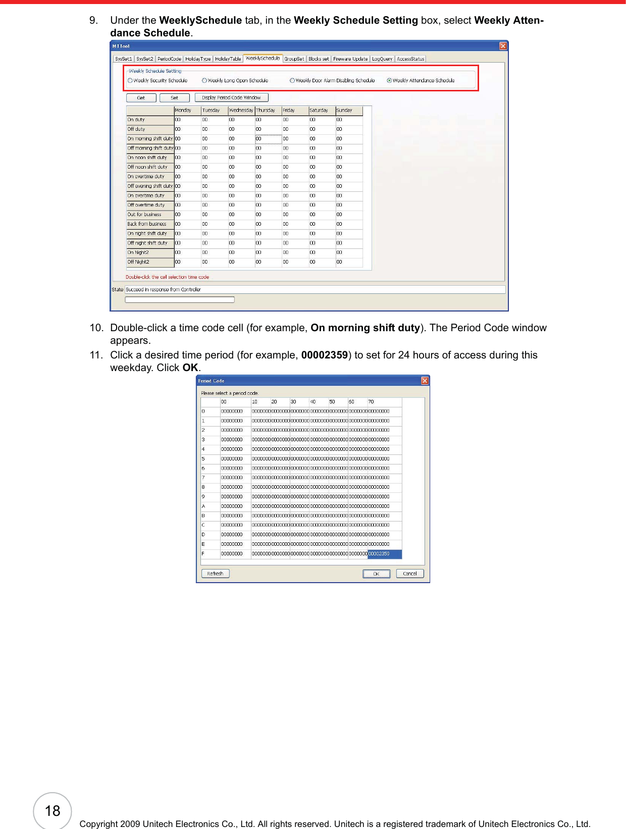
![Chapter 4 Advanced Setting4328. Click Apply oSend to send the command to the controller immediately.29. Click OK to return to the JanitorLite - [Permit Management] window.Scenario I - Normal Entrance and ExitSwipe the card on the internal reader, while in standby status. Entrancewith the user name APB displays on the standby screen indicating that reentry is not allowed.Swipe the card on the external reader, Exit with the user name APB dis-plays on the standby screen indicating that re-exiting is not allowed.Scenario II - Re-EnteringSwipe the card on the internal reader, Entrance with the user name APBdisplays on the standby screen.Swipe the card again on the internal reader, Re-Entering with the user name APB displays on the standby screen indicating that reentry occurred.Scenario III - Re-ExitingSwipe the card on the external reader, Exit with the user name APB dis-plays on the standby screen.UnitechAPBEntrance2009.1.8 Thur.UnitechAPBExit2009.1.8 Thur.UnitechAPBEntrance2009.1.8 Thur.UnitechAPBRe-Entering2009.1.8 Thur.UnitechAPBExit2009.1.8 Thur.](https://usermanual.wiki/Unitech-Electronics/MT18EM01/User-Guide-1141754-Page-49.png)