Unitech Electronics MT18MIFARE01 An Economy Versatile T&A; Terminal User Manual
Unitech Electronics Co., Ltd. An Economy Versatile T&A; Terminal
User manual
A Versatile Multi-Function Terminal
User Manual
Talk
Mic
400664G Version 3.0


i
Preface
About This Manual
This manual explains how to install, operate and maintain MT180 IP-based Access Control
Terminal.
No part of this publication may be reproduced or used in any form, or by any electrical or
mechanical means, without permission in writing from the manufacturer, which includes but is
not limited to photocopying, recording, or information storage and retrieval systems. The
material in this manual is subject to change without notice.
© Copyright 2009 Unitech Electronics Co., Ltd. All rights reserved.
Unitech TASHI Website: http:\\www.unitech-sbd.com
Unitech Global Website: http:\\www.unitech-adc.com
Regulatory Compliance Statements
FCC Warning Statement
This equipment has been tested and found to comply with the limits for a Class B digital
device, pursuant to part 15 of the FCC rules. These limits are designed to provide reasonable
protection against harmful interference in a residential installation.
This equipment generates, uses and can radiate radio frequency energy and, if not installed
and used in accordance with the instructions, may cause harmful interference to radio com-
munications. However, there is no guarantee that interference will not occur in a particular
installation. If this equipment does cause harmful interference to radio or television reception,
which can be determined by turning the equipment off and on, the user is encouraged to try to
correct the interference by one or more of the following measures:
– Reorient or relocate the receiving antenna.
– Increase the separation between the equipment and receiver.
– Connect the equipment into an outlet on a circuit different from that to which the
receiver is connected.
– Consult the dealer or an experienced radio/TV technician for help.
Any changes or modifications (including the antennas) made to this device that are not
expressly approved by the manufacturer may void the user’s authority to operate the
equipment.
ii
Canadian Compliance Statement
Industry Canada Notice Operation is subject to the following two conditions: (1) This device
may not cause interference and (2) This device must accept any interference, including inter-
ference that may cause undesired operation of the device.
European Conformity Statement
Declaration of Conformity with Regard to the R&TTE 1999/5/EC and EMC 89/336/ EEC direc-
tives.
RoHS Statement
This device conforms to RoHS (Restriction of Hazardous Substances)
European Union regulations that set maximum concentration limits on
hazardous materials used in electrical and electronic equipment.
Taiwan NCC Warning Statement
ᖕ ˡ˖˖ ܅פሽंᘿ୴ࢤሽᖲጥᙄऄʳࡳ ˍ
รԼԲයΓᆖীڤᎁᢞٽհ܅פ୴᙮ሽᖲΔॺᆖױΔֆΕᇆࢨࠌشृ݁լᖐ۞᧢
ޓ᙮ΕףՕפࢨ᧢ޓૠհࢤ֗פ౨Ζ
รԼයΓ܅פ୴᙮ሽᖲհࠌشլᐙଆڜ٤֗եឫٽऄຏॾΙᆖ࿇ڶեឫွழΔ
ᚨمܛೖشΔࠀޏ۟ྤեឫழֱᤉᥛࠌشΖ
ছႈٽऄຏॾΔਐࠉሽॾऄࡳ܂ᄐհྤᒵሽຏॾΖ܅פ୴᙮ሽᖲႊݴ࠹ٽऄຏ
ॾࢨՠᄐΕઝᖂ֗᠔᛭شሽंᘿ୴ࢤሽᖲໂհեឫΖ
Warranty
Under Unitech limited Warranty, the following items are covered:
• MT180 IP-based Access Control Terminal - 1-year limited warranty.
• Cables - three month limited warranty.

iii
Table of Contents
Preface
About This Manual .................................................................................... i
Regulatory Compliance Statements .................................................................... i
FCC Warning Statement ................................................................................. i
Canadian Compliance Statement................................................................... ii
European Conformity Statement .................................................................... ii
RoHS Statement............................................................................................. ii
Taiwan NCC Warning Statement ................................................................... ii
Warranty ............................................................................................................. ii
Chapter 1
Getting Started ........................................................................................ 1
Introducing MT180.............................................................................................. 1
Features ......................................................................................................... 1
Setting up MT180 ............................................................................................... 2
Connecting Power .......................................................................................... 2
Identifying LED Indicator Lights...................................................................... 2
Establishing Terminal-PC Connection............................................................ 3
Setting Date and Time.................................................................................... 4
Utilizing Software............................................................................................ 4
Chapter 2
Using the Hardware ................................................................................ 5
Using the Keypad ............................................................................................... 5
Using Proximity Reader ...................................................................................... 6
Using Fingerprint Reader.................................................................................... 8
Using DECT Phone (Optional).......................................................................... 11
Chapter 3
Onscreen Setting .................................................................................. 12
General Settings ............................................................................................... 12
Advanced Settings............................................................................................ 13
Chapter 4
Advanced Setting .................................................................................. 15
Shift Attendance ............................................................................................... 15
Scenario I - Swipe Card to Clock In.............................................................. 25
Security Operation ............................................................................................ 26
Scenario I - Place Security Ban.................................................................... 33
Scenario II - Lift Security Ban....................................................................... 33
Scenario III - Trigger Security Alarm ............................................................ 34
Anti-Pass Back Setting ..................................................................................... 34
Scenario I - Normal Entrance and Exit ......................................................... 43
Scenario II - Re-Entering.............................................................................. 43
Scenario III - Re-Exiting................................................................................ 43
Appendix A
System Specification............................................................................. 45

iv
Appendix B
Worldwide Support................................................................................ 46

1
Chapter 1
Getting Started
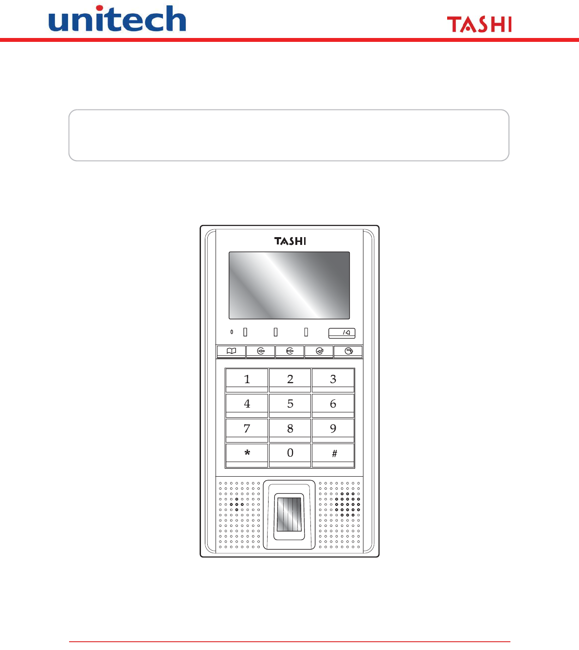
Introducing MT180
MT180 is a TASHI (Time & Attendance, Access Control, Security, Home Automation and Intercom) ter-
minal. It communicates with a central host security and T&A system through a standard Ethernet net-
work. The built-in proximity and fingerprint readers provide strict access control to a secure area.
Thanks for purchasing one of the most compact and cost-efficient access control and time and atten-
dance management solutions on the market.
Features
Powerful System
• 72 Mhz ARM7TDMI-S.
System Memory
• 8 MB Flash ROM.
Display
• COG/FSTN LCD with White Backlight.
• 128 x 64 Pixel Resolution.
User Interface
• 18 Hard Keys.
• LED Indicators (3).
Fingerprint Reader
• Fingerprint Capacity: 7,000.
Proximity Reader
• Card Capacity: 40,960.
• Supports reader types:
– EM, 125kHz.
– HID, 125kHz.
– MiFare, 13.56MHz.
Communication
• Ethernet 10/100M.
• RS485.
• Digital Inputs (3).
•Relay (2).
• DECT Voice (Optional).
I/O Expansion
• RS232 Drive (Secondary Reader).
• Digital Inputs (3).
• Digital Outputs (3).
Software Tools
• JanitorLite.
•MTTool.
• Communication Software Development
Kit.
2
Copyright 2009 Unitech Electronics Co., Ltd. All rights reserved. Unitech is a registered trademark of Unitech Electronics Co., Ltd.
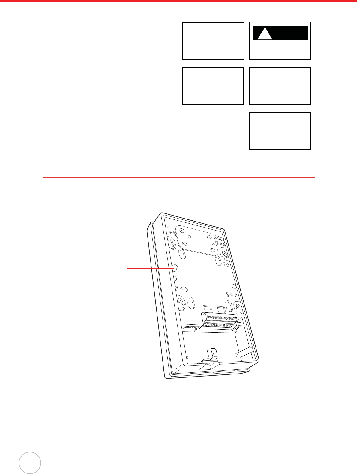
Setting up MT180
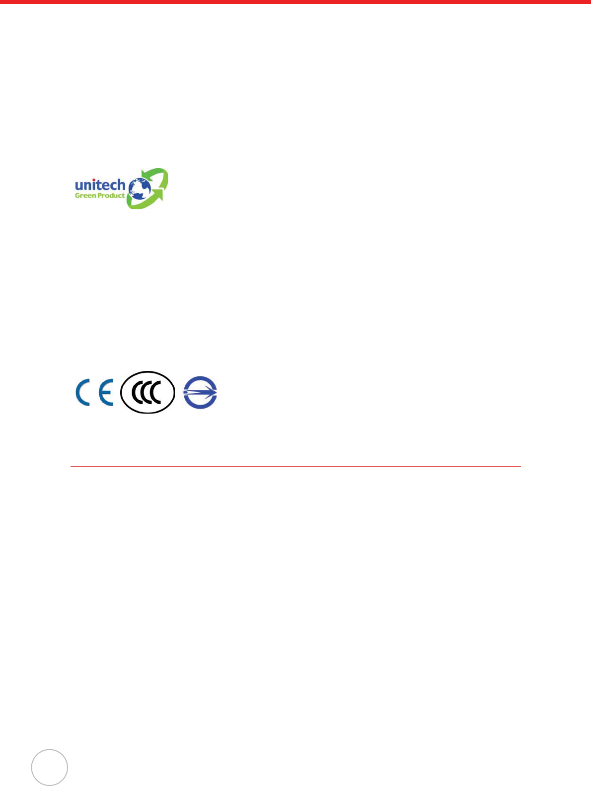
Connecting Power
Connect power to MT180 through the following:
1. Connect the AC Adapter into MT180’s DC Connector Port (1). Plug the AC Adapter into an
electrical outlet (2).
2. MT180 automatically starts!when the AC Adapter connects to an external power source. The
welcome screen appears before MT180 runs the module checking process.
NOTE: MT180 comes with an antitheft sensor inside the back panel. To setup MT180 before
installation, disable the alarm buzzer through one of the following:
1. Attach a magnet behind the sensor on the back panel.
2. Disable the antitheft function in the MT180 firmware (See Advanced Setting on
page 15).
3. Open the case and short circuit pin2 and pin3 of the J5 connector.
NOTE: When MT180 is installed or used, be sure that you set the backup battery switch to the
left to power ON MT180; if you do not use MT180 over a long period of time, please
right switch OFF the battery switch located above the terminal block to save the
backup battery power.
Identifying LED Indicator Lights
MT180 contains three LED indicators. For detailed descriptions, refer to the following:
Indicator Light Description
Blinking Yellow CPU normal operation.
Solid Yellow Terminal crash.
Solid Green Operation success.
For example: Swipe card success and enter the password success.
Solid Red Error occurred during operation.
For example: Invalid card.
1
2
Chapter 1 Getting Started
3
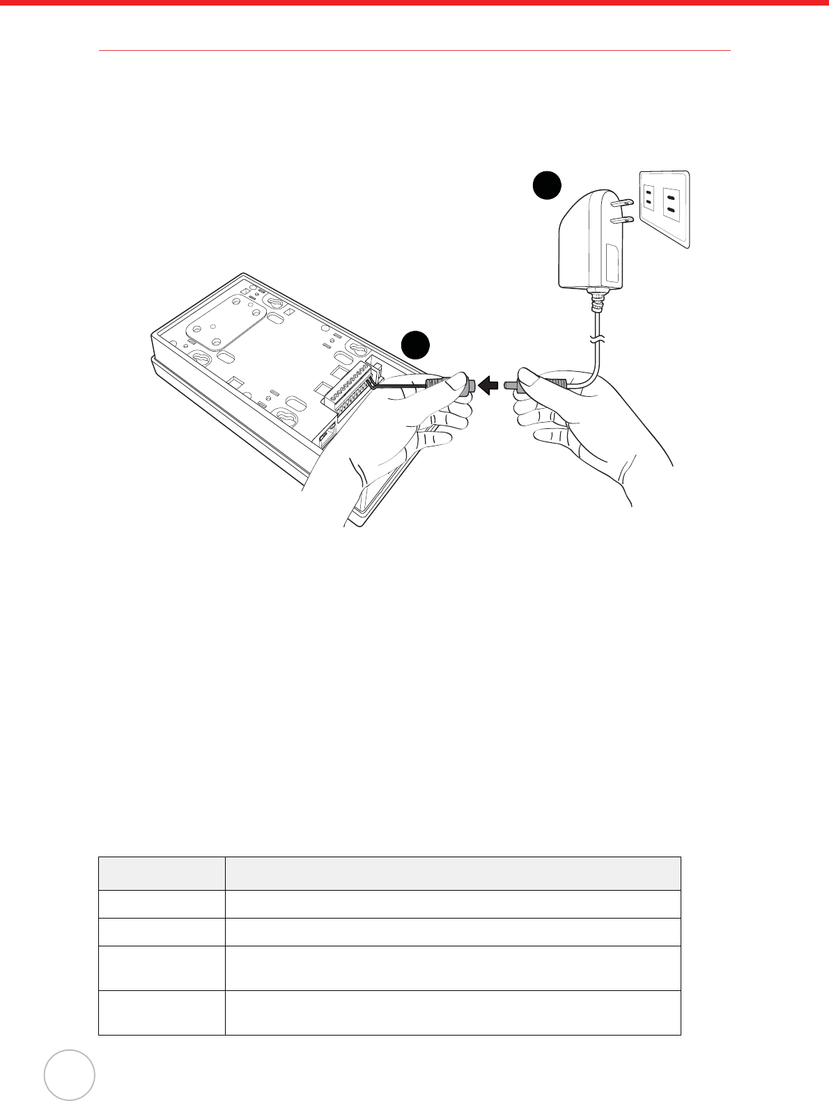
Establishing Terminal-PC Connection
Configure MT180 system settings after connecting power through an external power source. MT180
enables users to link to a host computer via Ethernet or RS485 interfaces for data communication.
MT180 can setup through MTTool or JanitorLite.
Unitech MTTool is a development program designed to help technical engineers customize access con-
trol, attendance control and manage function modules in a specified terminal (i.e. MT180). Connect
MTTool to MT180 through the following:
1. Connect MT180 and a computer to the network.
2. MT180’s default IP address is 192.168.2.127. Set the computer on the same subnet with
MT180.
For example, IP Address 192.168.2.100; Network Mask 255.255.255.0.
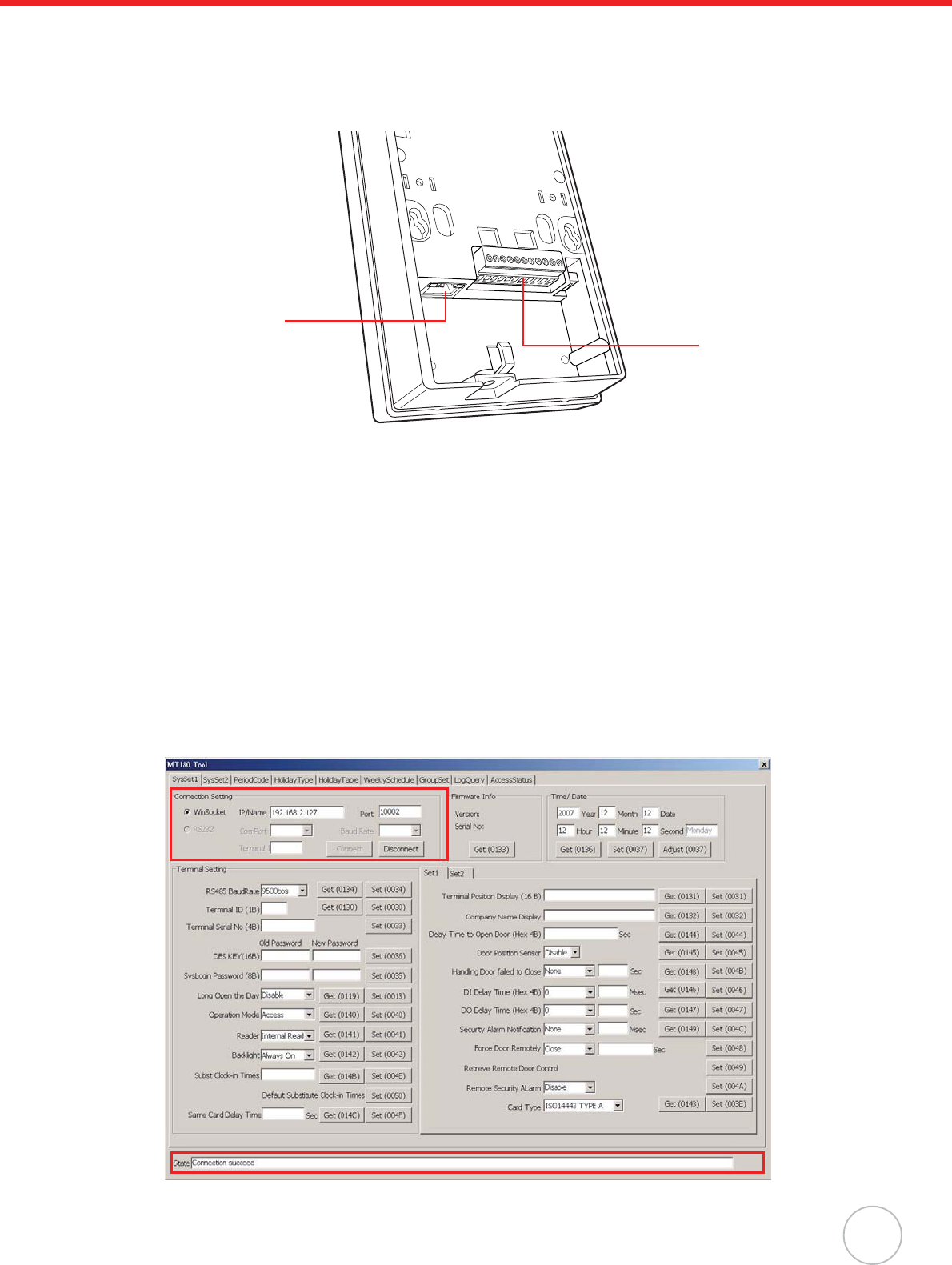
3. Make sure the TCP port 10002 is not occupied. If yJanitorLite is installed, stop the Unitech MT
Service in the Control Panel.
4. Disable any firewalls and execute MTTool.
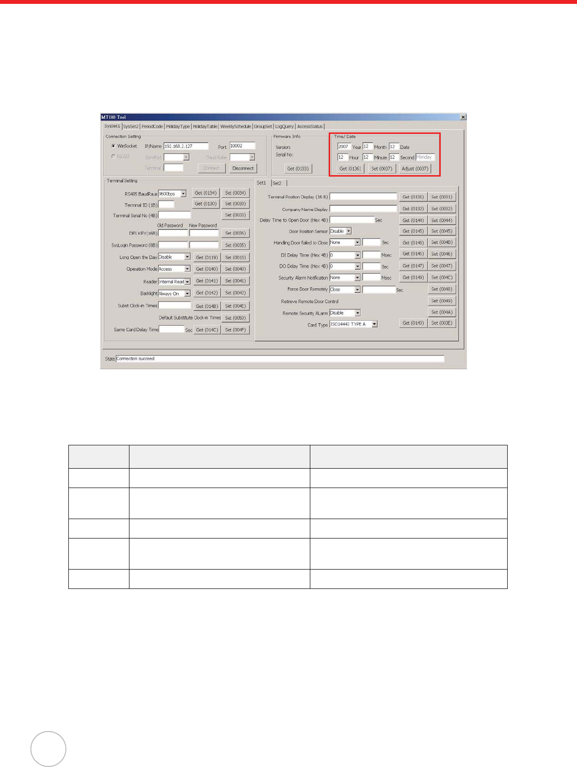
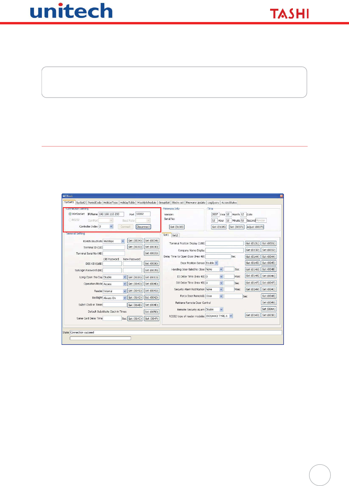
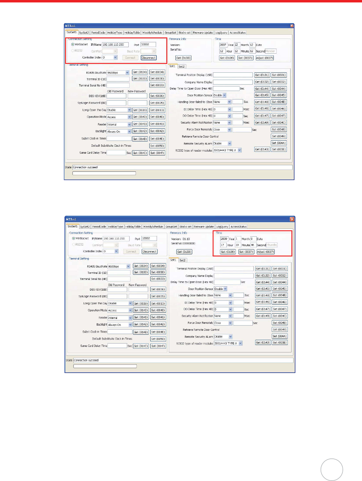
5. In MTTool, on the computer screen, under the SysSet1 tab, select WinSocket. In the IP/Name
field, input MT180’s default IP address 192.168.2.127 and in the Port field, input the default
port 10002.
6. Click Connect. The status bar at the bottom of MTTool displays Connection succeed , which
means MTTool has successfully cononected to MT180.
RS485
Port
Ethernet
Port
4
Copyright 2009 Unitech Electronics Co., Ltd. All rights reserved. Unitech is a registered trademark of Unitech Electronics Co., Ltd.
Setting Date and Time
Correct MT180 date and time in MTTool through the following:
• In MTTool and under the SysSet1 tab, locate the Time / Date field.
• Input the current date and time.
• Click Set.
NOTE: Click Adjust to synchronize MT180’s time with the computer’s time.
Utilizing Software
JanitorLite allows end users to apply a wide range of applications in the TASHI network. Learn about
the main differences between MTTool and JanitorLite through the following:
Please contact a Unitech representative to acquire MTTool. For more details please refer to the MTTool
User’s Manual or the JanitorLite User’s Manual.
Software MTTool (Free) JanitorLite (Optional)
Target Computer/Software Engineering. End User.
Operation
System
Windows on Computer (PC/ Notebook) Windows on the Computer (PC/Notebook).
Windows CE for MT380.
Network Standalone Terminal. Terminals/Controllers (As A Server).
Function Setting/Debugging/Maintenance. Setting/Managing Small to Large Scale
TASHI Networks.
Model MT180/MT380. MT180/MT380.
5
Chapter 2
Using the Hardware
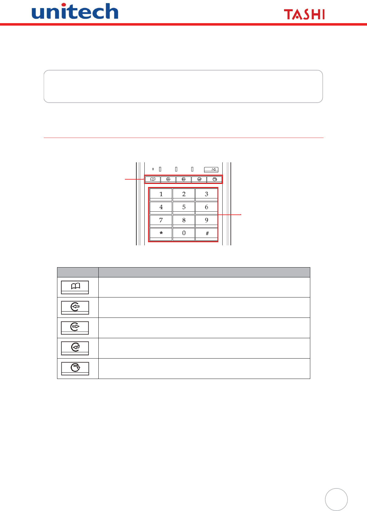
Using the Keypad
MT180 contains five function keys and 12 numeric keys.
MT180’s key functions are described in the following:
After powering on MT180, the standby screen displays the company name, system time and date,
which are configurable by pressing F1 button to enter the menu options.
While in standby status, press # during the password access period, and then follow the onscreen
prompt to input 2-digit group number and a 4-digit group access password to open the door.
In Access+Attendance Mode, press F2 or F3 to switch into Attendance Mode. Press F2 or F3 to choose
the work shift and swipe an ID card to clock in. To use the substitute clock in, press any key and follow
the onscreen prompt to input a user clock in number.
Key Main Function
Menu.
[F1]: Open menu options.
Clock in.
[F2]: Move upward through menu items.
Clock out.
[F3]: Move downward through menu items.
Break in.
[F4]: Returns to the previous menu item.
Break out.
[F5]: Enters a menu item or confirms a setting.
Talk
Mic
Function
Keys
Numeric
Keys
6
Copyright 2009 Unitech Electronics Co., Ltd. All rights reserved. Unitech is a registered trademark of Unitech Electronics Co., Ltd.
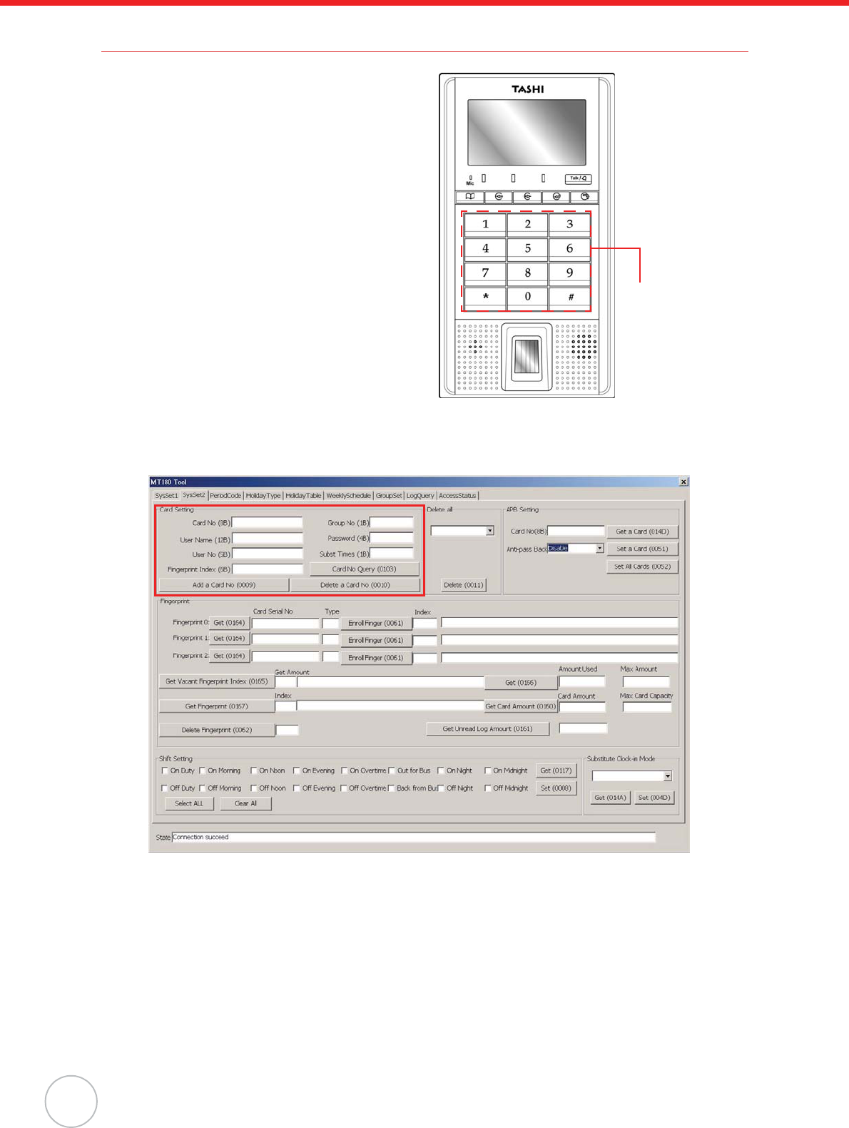
Using Proximity Reader
MT180 features a standard proximity reader, which
is compatible with all 125kHz EM, 125kHz HID, and
13.56MHz MiFare cards.
Utilize MTTool to add a card through the following:
1. Connect MT180 to a computer network. See
Establishing Terminal-PC Connection on
page 3.
2. Execute MTTool on the computer.
3. Enter the correct IP address and port num-
ber. Click Connect.
4. Follow MT180 onscreen instructions to enter
the Card Info Query option. See General
Settings on page 12.
Swipe the card over the Proximity Reader.
MT180 beeps three times.
The screen displays Invalid Card with the
card number.
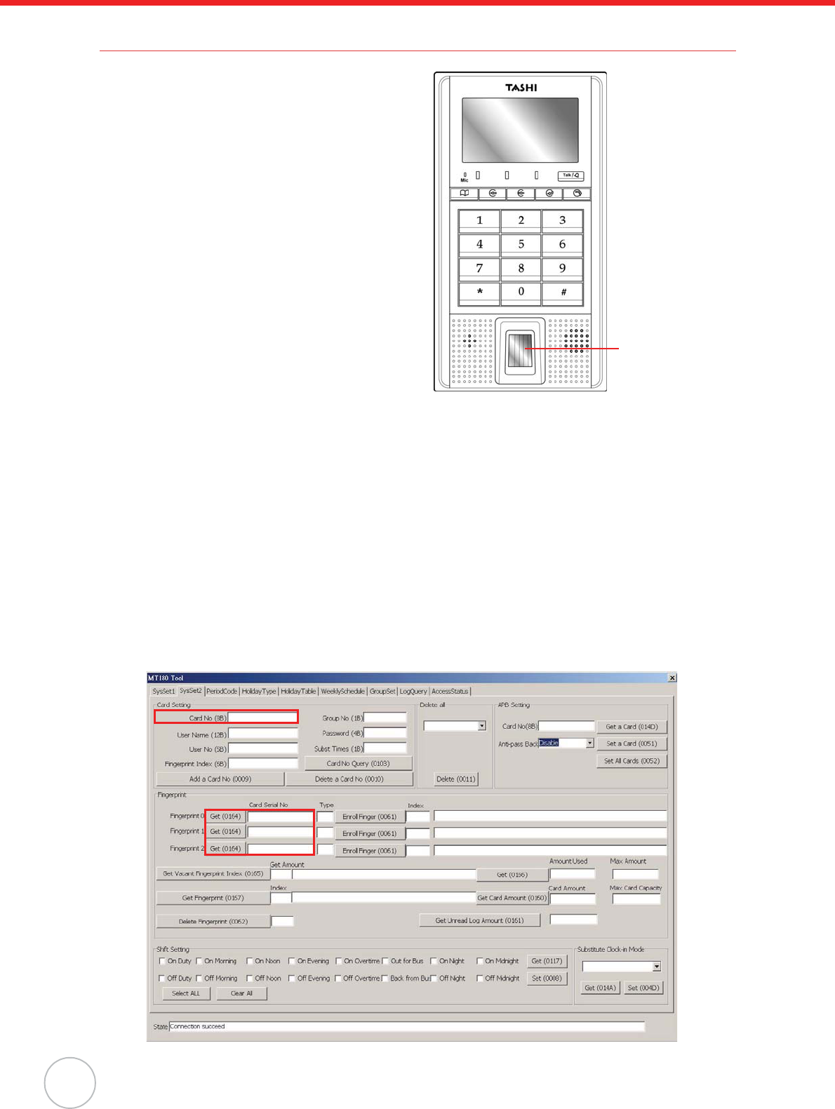
5. In MTTool, under the SysSet2 tab, in the
Card Setting box input the card number, user name, group number, password and etc.
6. Click Add a Card No. The status bar at the bottom of the MTTool screen displays Successful
terminal response informing that MTTool has successfully send the card to MT180.
NOTE: When adding a card, it is necessary to at least fill in the card number, user name, group
number and password. Otherwise, a prompt appears to ask for this specific informa-
tion.
Utilize JanitorLite to add a card through the following:
1. Connect MT180 to a computer network. See Establishing Terminal-PC Connection on page 3.
2. Enable Unitech MT Service in the Control Panel.
3. Click start oAll Programs oJanitorLite oJanitorLite.
Swipe card here
Chapter 2 Using the Hardware
7
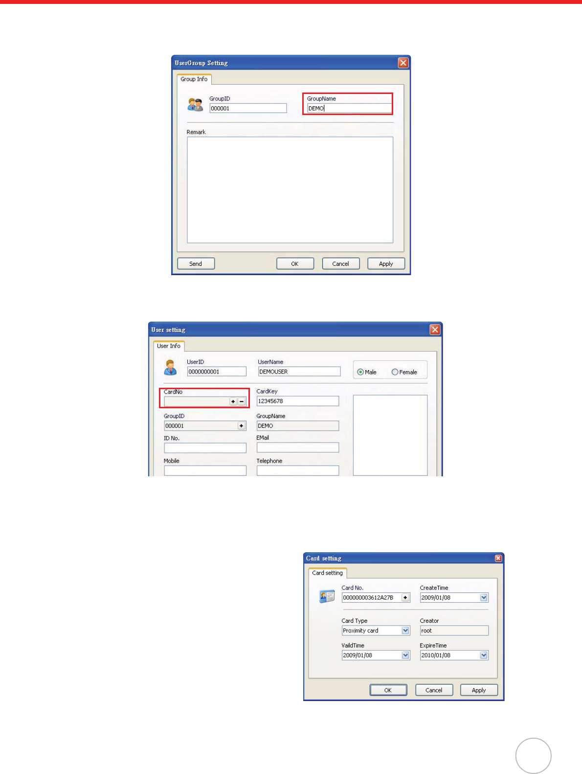
4. Click User o User Management.
Right-click All group. Select Append oGroup. The UserGroup Setting window appears.
Enter a group name (for example, DEMO). Click Apply oOK.
5. Right-click DEMO. Select Append o Entity. The User setting window appears.
Enter a user name (for example, DEMOUSER). In the CardNo. field, click +/ The Card setting
window appears.
NOTE: Make sure the card type is compatible with the reader.
6. Follow MT180’s onscreen instructions to enter the Card Info Query. See General Settings on
page 12. Swipe the card over the Proximity Reader. MT180 beeps three times.
The screen displays Invalid Card with the card number.
7. Input the card number in the Card No.
8. Click Apply oOK to return to the User set-
ting window.
9. Click Apply oOK.
NOTE: The card will not immediately be to
MT180, but it will be sent periodi-
cally via Unitech MT Service. The
default value is five minutes. It is
optional to modify the interval setting
in the MT Service Tool.
8
Copyright 2009 Unitech Electronics Co., Ltd. All rights reserved. Unitech is a registered trademark of Unitech Electronics Co., Ltd.
Using Fingerprint Reader
MT180 has an optional integrated Fingerprint reader
that enrolls and verifies and verify fingerprints. The
reader can store up to 7,000 fingerprint templates.
Each user is allowed to have a maximum of three
fingerprints.
NOTE: Make sure the card is valid.
Enroll a fingerprint through the following:
1. Press F1.
2. Select General oAdd Finger.
3. Swipe the card.
4. Place a finger in the Fingerprint Reader and
adjust the finger placement according to the
onscreen instructions.
The screen may inform that the finger is too
high, too low, too left, too right, too small or
no finger. Remove and place the finger on
the fingerprint reader three times.
5. Press F3 to enroll another fingerprint when the screen displays Collect finger OK.Continue?.
Press F5 to stop.
6. After enrolling the finger on the fingerprint Reader three times, the screen displays CollectFin-
ger OK and return to the standby screen.
Utilize MTTool to collect fingerprints through the following:
1. Connect MT180 to a computer network. See Establishing Terminal-PC Connection on page 3.
2. Execute MTTool on the computer.
3. Enter the correct IP address and port number. Click Connect.
4. Under the SysSet2 tab, enter a card number in the Card No. field and click Card No Query.
Value FFFFFFFFFFFF displays in the Fingerprint Index field, which indicates empty finger-
print data for the card.
In the Card Serial No field, input the card number and click Get. Now fingerprint data can
extract from this card.
Swipe Finger
Here
Chapter 2 Using the Hardware
9
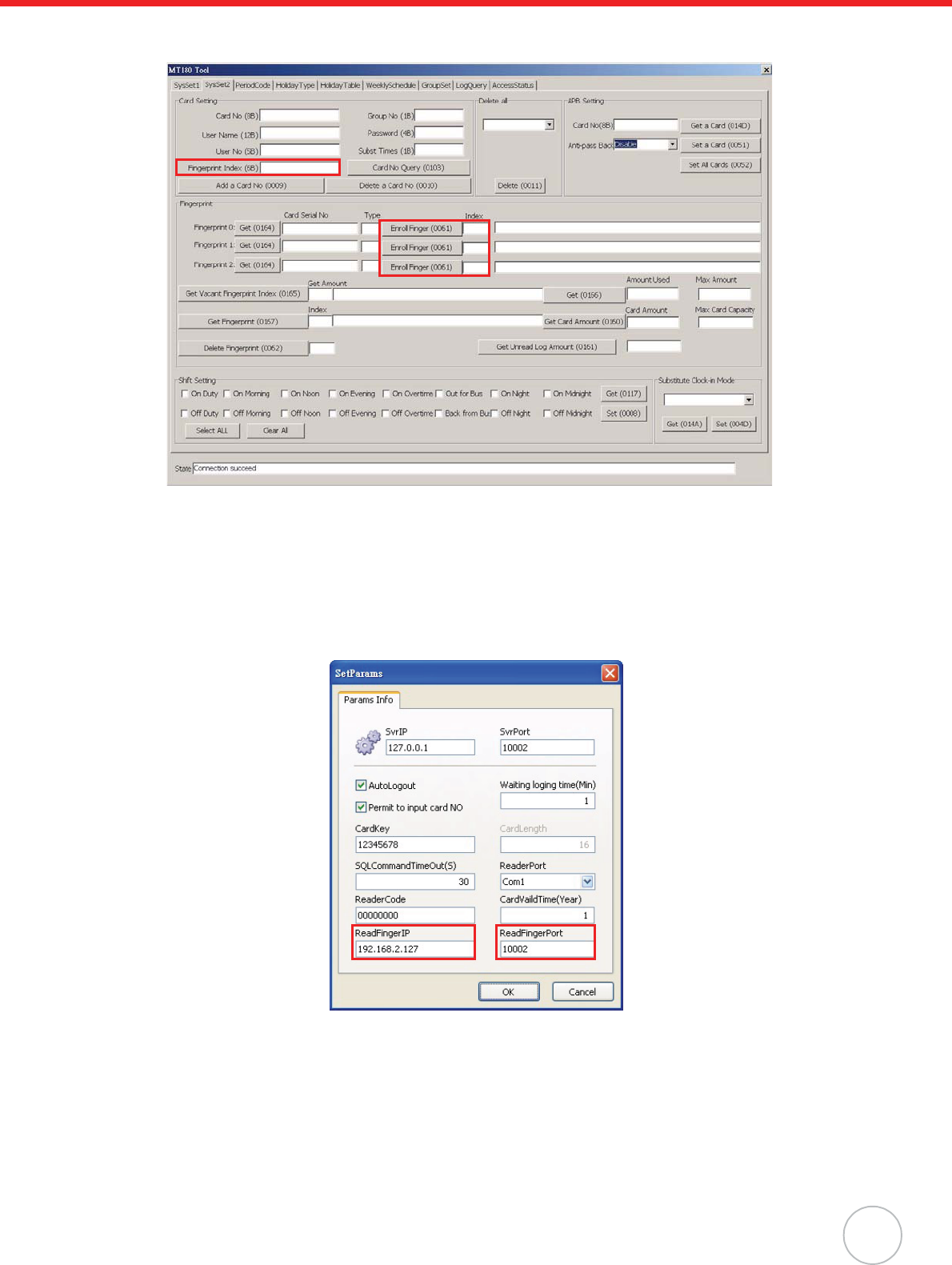
5. To enroll the first fingerprint for this card, input 0000 in the Index field and click Enroll Finger
(1). Input 000000000000 in the Fingerprint Index field and click Add a Card No (2).
Utilize JanitorLite to collect fingerprints through the following:
1. Connect MT180 to a computer network. See Establishing Terminal-PC Connection on page 3.
2. Enable Unitech MT Service in the Control Panel.
3. On the computer screen, click start oAll Programs oJanitorLite oJanitorLite.
4. Click System oSysParams Setting. The SetParams window appears.
Specify the IP address and port number of the fingerprint reader. Click OK.
1
2
10
Copyright 2009 Unitech Electronics Co., Ltd. All rights reserved. Unitech is a registered trademark of Unitech Electronics Co., Ltd.
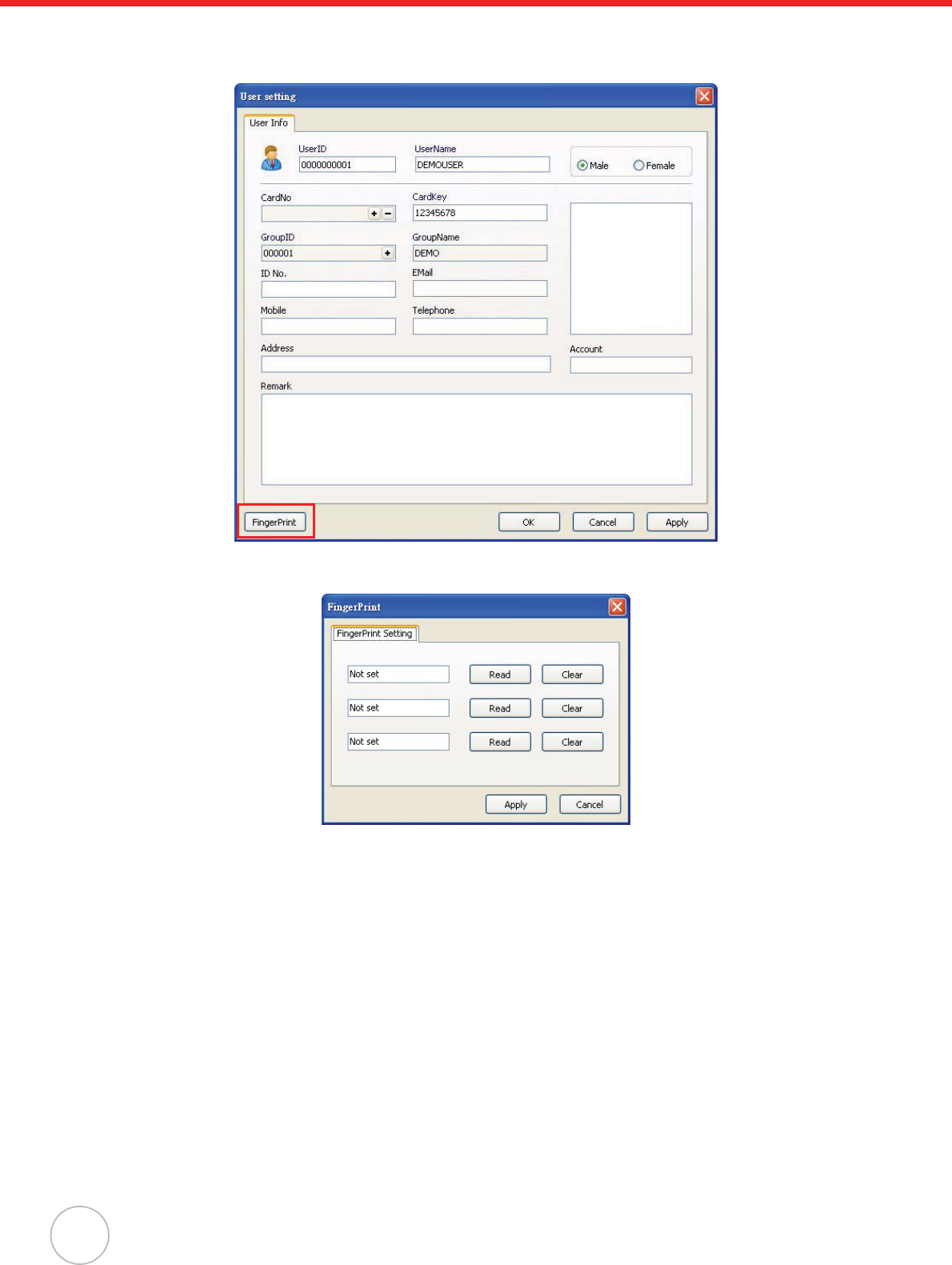
5. Click User oUser Management.
Double-click DEMOUSER. The User setting window appears.
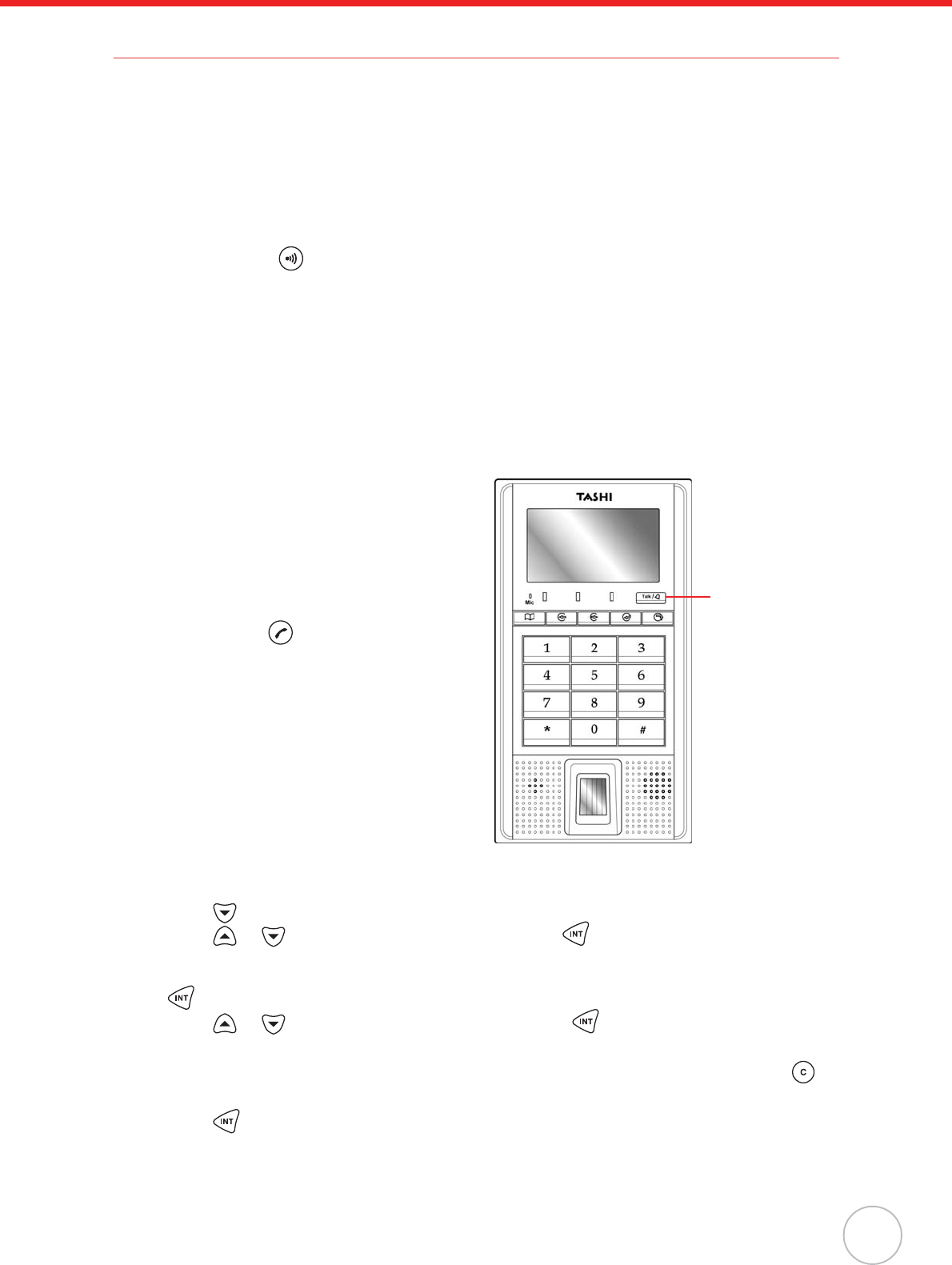
Click FingerPrint. The FingerPrint window appears.
6. To collect fingerprint data from MT180, click Read. The value Not set changes into Already
Setting, if the fingerprint reading is successful. Click Apply.
7. Click Apply, and then OK.
Chapter 2 Using the Hardware
11
Using DECT Phone (Optional)
MT180 has an optional DECT module that can make intercom calls. The procedures for registering
MT180 to DECT base stations may vary between phone service providers. MT180 can register up to
four base stations.
Register MT180 to an AWTEK base station through the following:
NOTE: Before registration, make sure the voice module is properly installed while MT180 pow-
ers on through the running module checking process.
1. Press and hold on the back panel of the base station for 15 - 20 seconds. The LED indica-
tor on the front panel flashes.
2. Press F1 to enter the terminal menu.
3. Press F3 to select the Advanced option.
4. Press F5 to enter the Advanced option.
5. Enter the system login password (12345678, by default) and press F5 to confirm.
6. Enter the Voice Park option. The screen displays Voice Module Parking OK when registration
is completed.
Make an intercom call by using an AWTEK DECT phone through the following:
1. Press Talk/Doorbell. MT180 connects to the
DECT phone while the screen displays Con-
nect... Please wait!.
The LED indicator on the DECT phone
flashes and the phone rings with the
MT180’s HS number (HS1, by default)
shown onscreen.
2. Press answer to receive the call. MT180
beeps while the screen displays Calling...,
the duration of this call is shown on the
DECT phone screen.
3. Press À on the DECT phone, to trigger the
door open.
NOTE: Ensure the relay wiring is ready.
Cancel registration by using a registered handset.
Cancel MT180’s registration on an AWTEK DECT phone handset through the following:
1. Press to enter the main menu.
2. Press or to select the BS setting option. Press to confirm. The screen displays
Waiting....
3. Follow the onscreen prompt to input the base station’s Master PIN (0000, by default) and press
to confirm. A confirmation sound beeps, and the sub menu opens.
4. Press or to select the Remove HS option. Press to confirm. The screen displays
Remove HS1/2/3/4/5?.
5. Follow the onscreen prompt to input MT180’s HS number (1/2/3/4/5, by default) or press to
cancel.
1. Press to confirm. A confirmation sound beeps, and the screen displays Not sub when this
setting is done.
Press the button
12
Chapter 3
Onscreen Setting
This chapter introduces MT180’s general and advanced settings.
General Settings
Press F1 to enter the terminal menu.
Press F5 to enter the General option.
Five options are available:
• SysInfoQuery.
• CardInfoQuery.
• AddFinger.
• ModifyCardPIN.
• LongTimeDoor.
Enter the SysInfoQuery option to get the terminal information.
The five options are described through the following:
Enter the CardInfoQuery option. Follow the onscreen prompt to swipe a card. The screen displays the
card number, user name, user number and group number preset in JanitorLite or MTTool.
Enter the AddFinger option. Follow the onscreen prompt to swipe a card. The screen displays an
Operation Notice. Follow the operation notice and place a finger on the fingerprint reader. Each card
allows to enroll a maximum of three fingerprints.
Enter the ModifyCardPIN option. Follow the onscreen prompt to swipe a card. The screen displays
Input old PIN. Using the numeric keypad to enter the card password and press F5 to confirm. The
screen displays Input new PIN. And Input again. The screen displays Modify Card PIN Success
upon successful modification.
Sys Info Query Description
Location Displays the terminal location (#Controller 01, by default).
Version&SNR Displays the terminal firmware version and serial number.
WorkMode Displays current operation mode (Access Mode, by default).
ModuleStatus Displays the modules status of Flash1, Flash2, Finger, Reader1,
Reader2, Voice and Network. If the module operates normally, the
screen displays ok; if not, the screen displays error.
Card&Finger Displays the maximum card/fingerprint capacity and current card/finger-
print count.
>OperationSel<
>>General
X Advanced
Chapter 3 Onscreen Setting
13
Enter the LongTimeDoor option. It is possible to enable/disable the open door function for a select
period of time. Follow the onscreen prompt to swipe the card before this setting is activated (Whether
Turn on or Turn off is selected) and the screen displays Auto-OpeningDoorTurn on/off.
Advanced Settings
Press F1 to enter the terminal menu.
Press F3 to select the Advanced option.
Press F5 to enter the Advanced option.
Using the numeric keypad to enter the default system login password
12345678, and press F5 to confirm. Ten options are available:
• Set Device ID.
•SetBaudrate.
• SetLanguage.
• SetBacklight.
• SetNetwork.
•VoicePark.
• Reboot.
• ResumeDefault.
• Anti-thief.
•Exit.
Enter the Set Device ID option. Specify the terminal ID (001, by default).
Enter the SetBaudrate option. Select a baud rate (115200 bps, by default) to match the computer.
Available rates are 9600,19200,38400 and 115200 bps. The larger number equates to a faster con-
nection speed.
Enter the SetLanguage option to switch the terminal language. Current supported languages are Eng-
lish, Simplified Chinese and Traditional Chinese.
Enter the SetBacklight option to set the backlight behavior. Select AlwaysTurnOn, to have the back-
light to stay on all the time. Select AlwaysTurnOff, to have the backlight turn off all the time. Select
TurnOnOnwork, to have the backlight turn on when a button is pressed.
Enter the SetNetwork option to configure the network settings.
Set Network Description
Set Net Password Enter the network password.
Set IP Address Enter the IP address (192.168.2.127, by default).
Set Net Mask Enter the network mask (255.255.255.0, by default).
Set Gateway Configure the network gateway.
Set Port Number Specify a local port number (10002, by default). The maximum valid
port number is 65535.
Set Baud Rate Select a serial port baud rate (115200 bps, by default). Available rates
are 9600,19200,38400,57600 and 115200 bps. The larger number
equates to a faster connection speed.
Confirm Setting Select Yes to confirm the network settings. The screen displays Modify
network success!.
Select No to go back to SetNetwork options.
>OperationSel<
X General
>> Advanced

14
Copyright 2009 Unitech Electronics Co., Ltd. All rights reserved. Unitech is a registered trademark of Unitech Electronics Co., Ltd.
Enter the VoicePark option to detect the optional DECT function. If the DECT phone is properly
installed, the screen displays ParkOK. If not, the screen displays ParkError. If the voice module is not
installed or installed improperly, the screen displays VoiceModuleParkingError.
Enter the Reboot option. Select Yes to reboot the system. The screen displays Device reboot. Please
wait! and the system reboots itself. Select No to go back to the Advanced options.
Enter the ResumeDefault option. Select Yes to reset the factory defaults. The screen displays
Resume default. Please wait! and MT180 reboots itself. Select No to go back to the Advanced
options.
Enter the Anti-thief option. Select Yes to enable the sensor and go back into the Advanced options.
Select No to disable the sensor and go back to the Advanced options.
Enter the Exit option. Log out the system advanced settings and return to the standby screen.
15
Chapter 4
Advanced Setting
This chapter introduces how to utilize MT180 configuration software for diverse applications.
Shift Attendance
Utilize MTTool to manage time and attendance through the following:
1. Set MT180 to a computer on the same subnet network.
2. Execute MTTool on the computer.
3. In MTTool and under the SysSet1 tab, select WinSocket. Input the IP address (for example,
192.168.110.230). Click Connect.
NOTE: See Advanced Settings on page 13 to set MT180’s IP address.
16
Copyright 2009 Unitech Electronics Co., Ltd. All rights reserved. Unitech is a registered trademark of Unitech Electronics Co., Ltd.
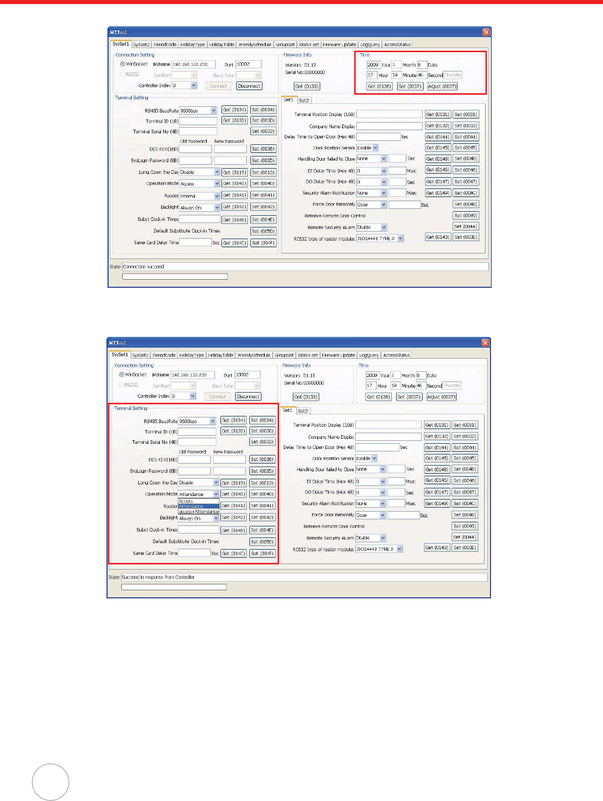
4. In the Time box, click Adjust to synchronize the system time with the computer.
5. Click Get to double check MT180’s date and time settings.
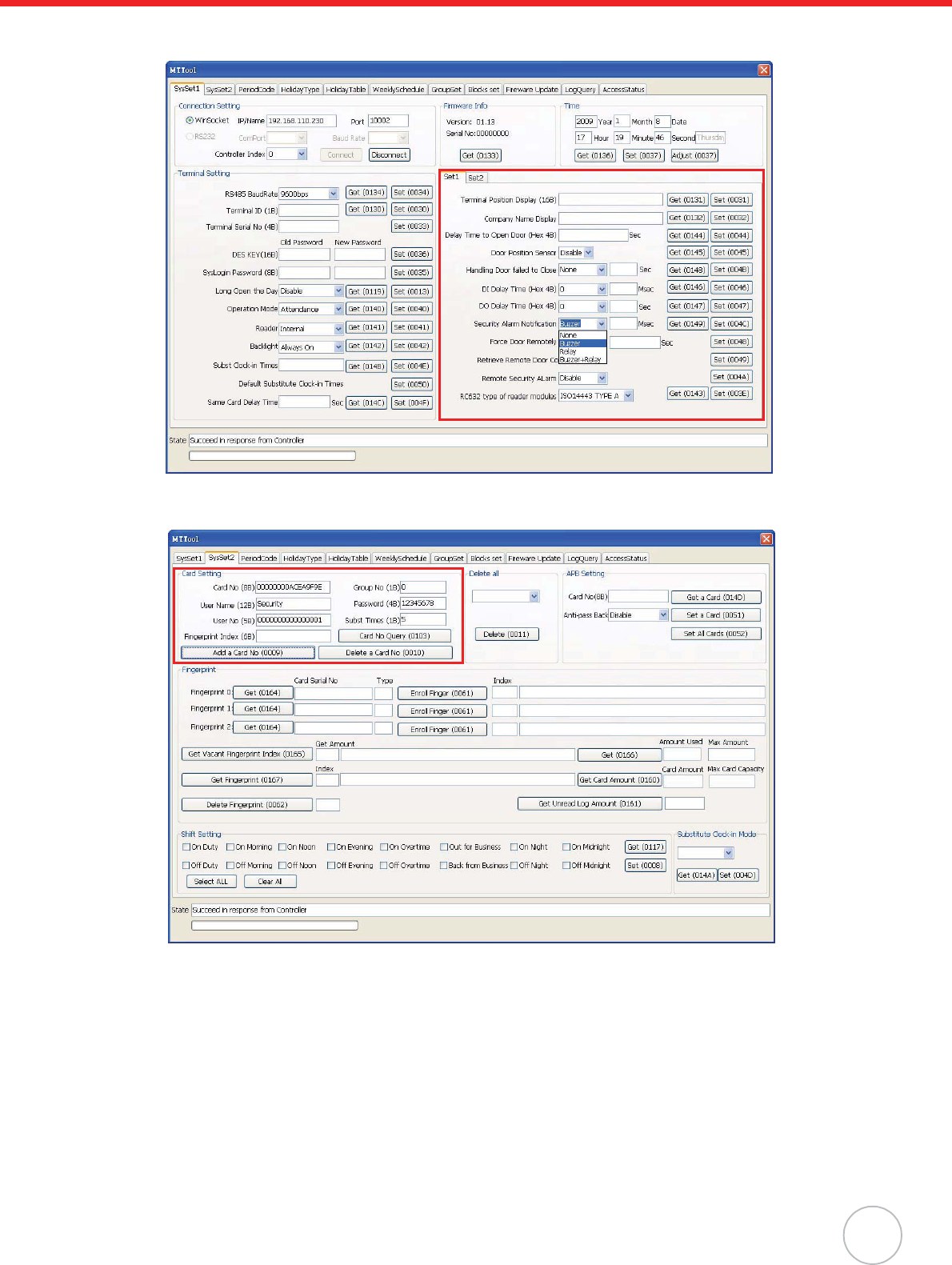
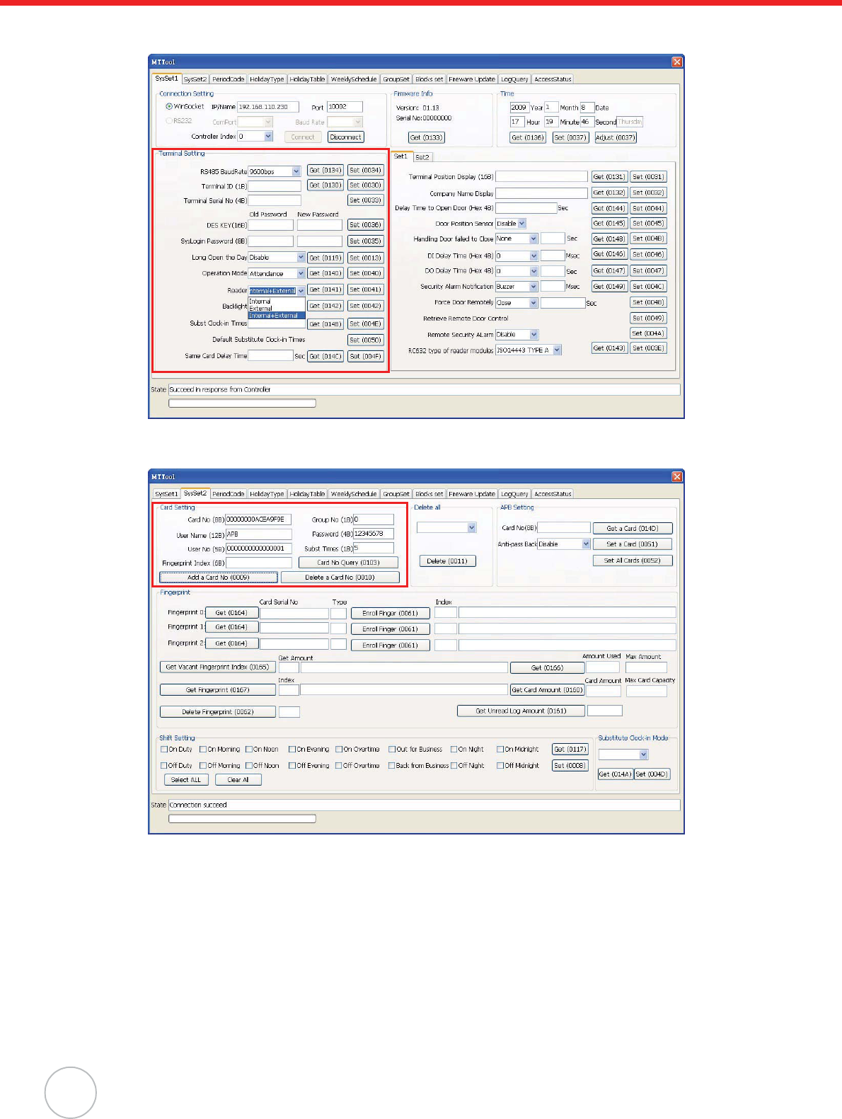
6. In the Terminal Setting box, select Attendance from the Operation Mode drop down menu.
Click Set.
Chapter 4 Advanced Setting
17
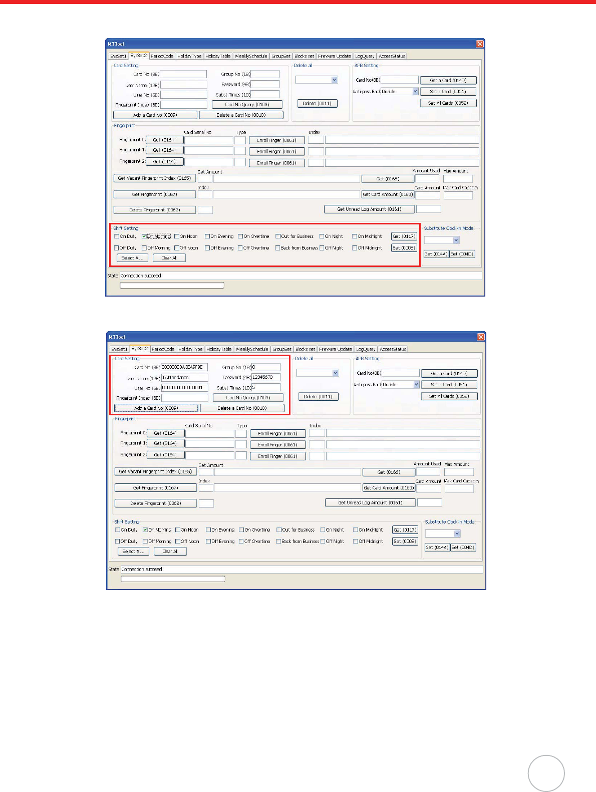
7. Under the SysSet2 tab, in the Shift Setting box, check a desired work shift (for example, On
Morning). Click Set.
8. In the Card Setting field, input the card number, user name, user number, group number and
etc. Click Add a Card No.
NOTE: See General Settings on page 12 to acquire the card number.
18
Copyright 2009 Unitech Electronics Co., Ltd. All rights reserved. Unitech is a registered trademark of Unitech Electronics Co., Ltd.
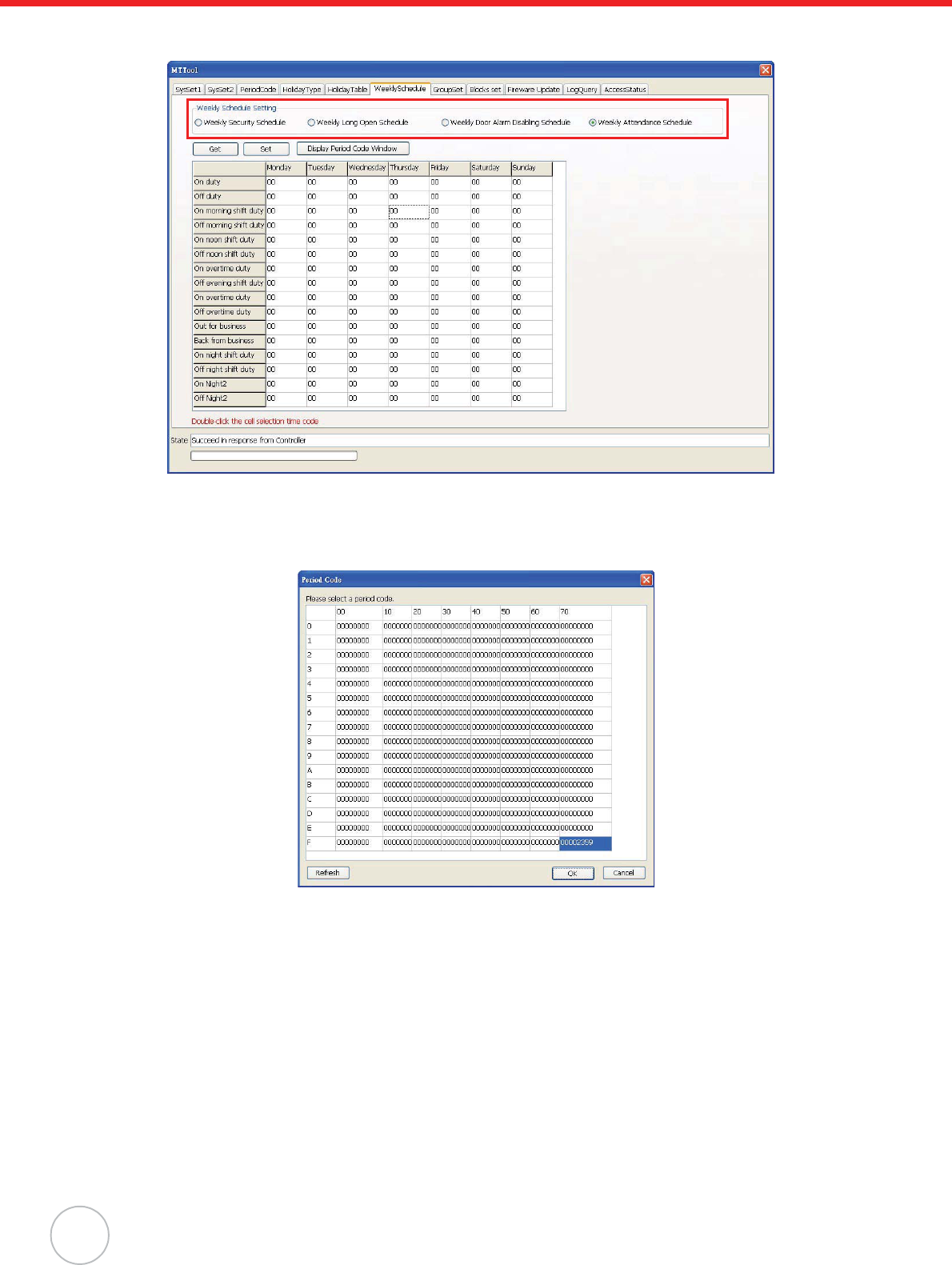
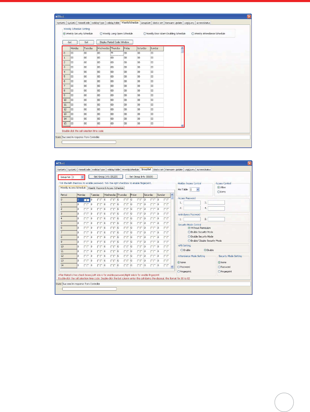
9. Under the WeeklySchedule tab, in the Weekly Schedule Setting box, select Weekly Atten-
dance Schedule.
10. Double-click a time code cell (for example, On morning shift duty). The Period Code window
appears.
11. Click a desired time period (for example, 00002359) to set for 24 hours of access during this
weekday. Click OK.
Chapter 4 Advanced Setting
19
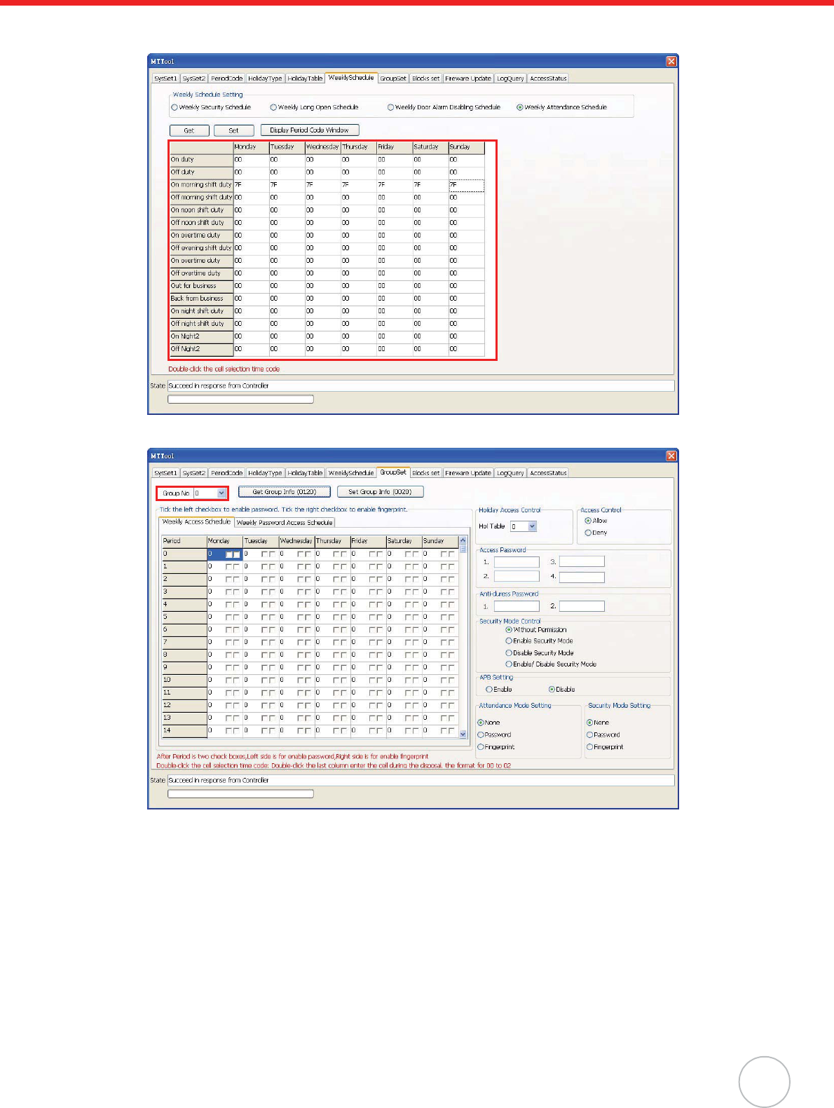
12. Select time period codes for this work shift in other weekdays. The period code 7F displays on
the shift row. Click Set.
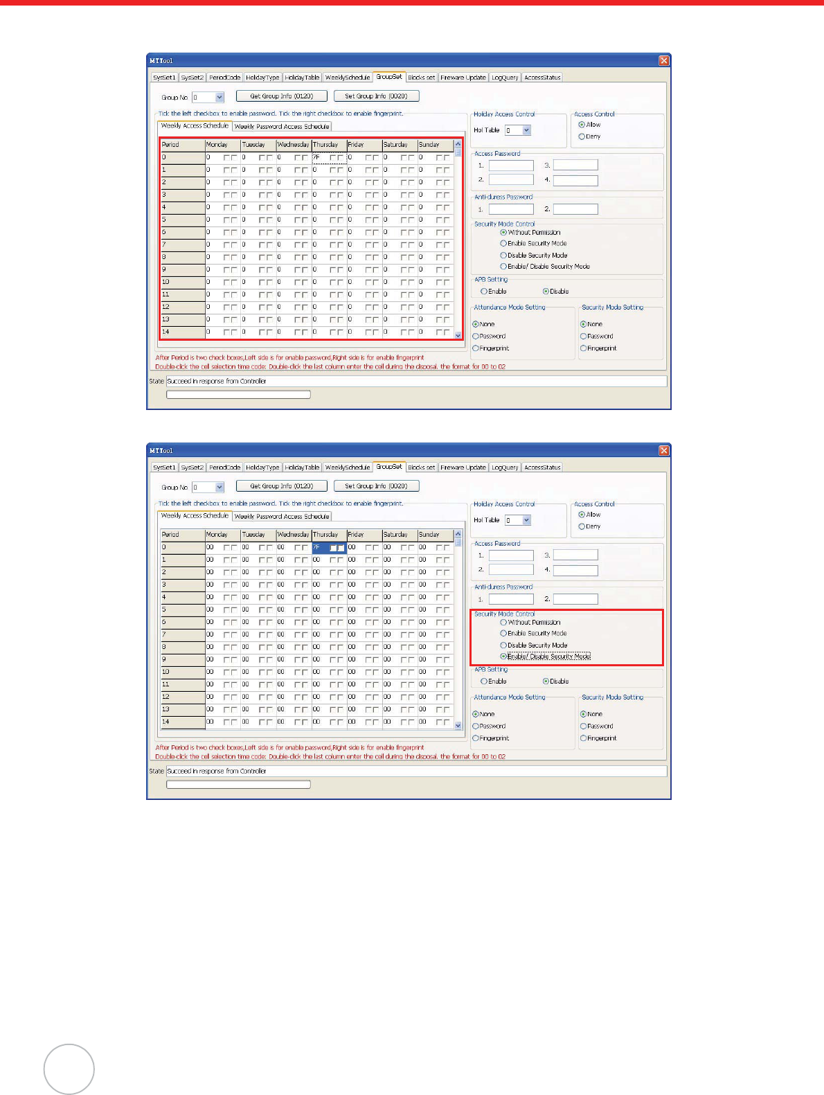
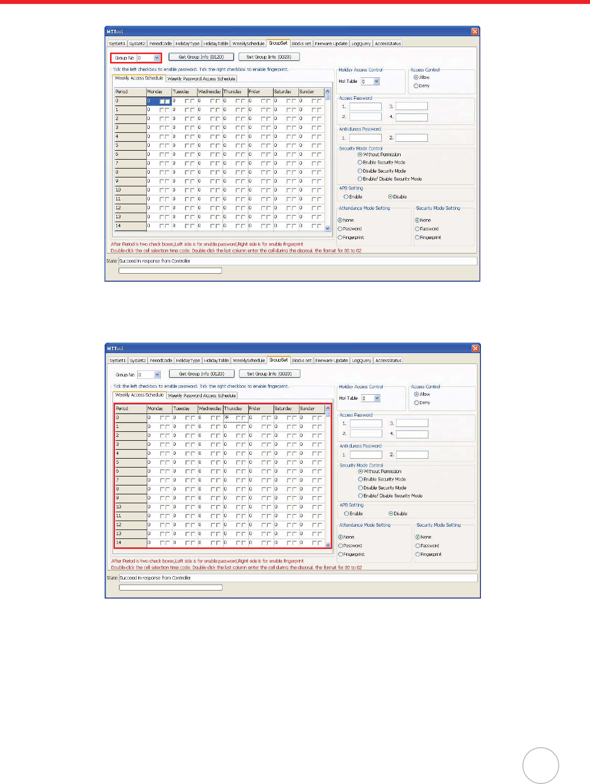
13. In the GroupSet tab, select the desired group (for example, 0).
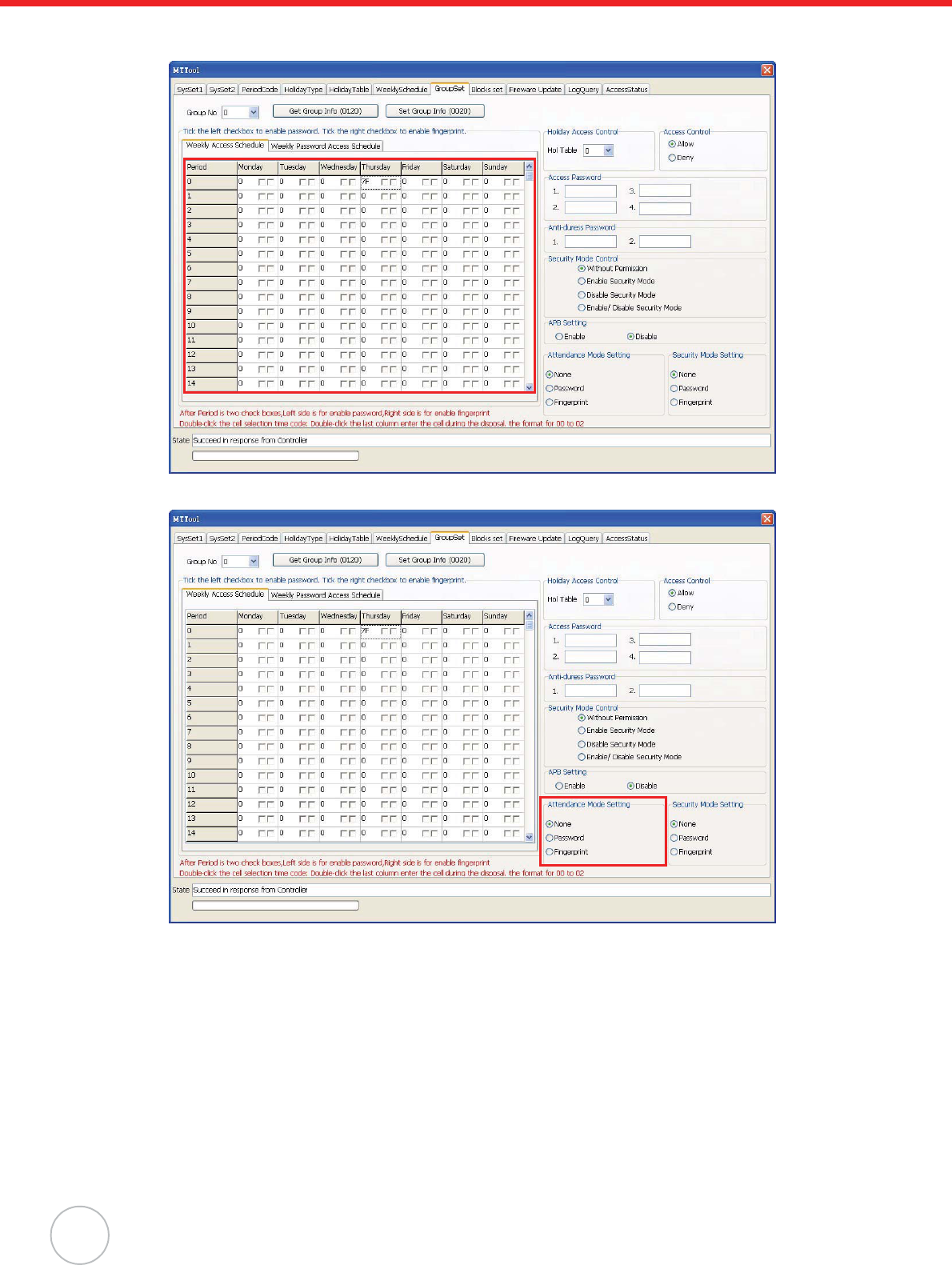
14. Double-click on a desired table cell (for example, row 1 /column Thursday). The Period Code
window appears.
20
Copyright 2009 Unitech Electronics Co., Ltd. All rights reserved. Unitech is a registered trademark of Unitech Electronics Co., Ltd.
15. Click a desired time period (for example, 00002359) to set for 24 hours of access in this week-
day. Click OK. The period code 7F displays on the table cell.
16. In the Attendance Mode Setting box, select None.
17. Click Set Group Info, on the top center of the screen.
Utilize JanitorLite to manage time and attendance through the following:
1. Set MT180 to a computer on the same subnet network.
NOTE: Switch the controller operation mode to Attendance, and synchronize the date and
time in MTTool.
2. On the computer screen click start oAll Programs oJanitorLite oJanitorLite.
3. Click Controller oController Management.
Chapter 4 Advanced Setting
21
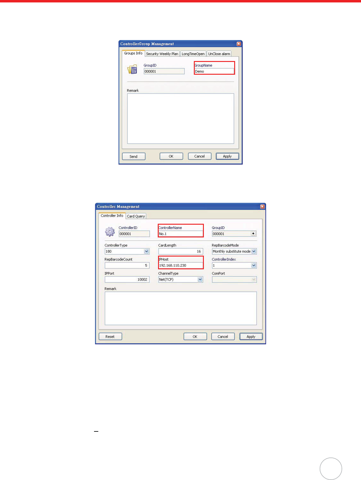
4. Right-click All Groups, and click Append o Group to add a new controller group. The Con-
troller Group Management window appears.
5. Enter the controller group name (for example, DEMO). Click Apply, and then OK to return to
the Controller Group Management window.
6. Right-click the desired group (for example, DEMO), and click Append oEntity to add a new
controller. The Controller Management screen appears.
7. Enter the controller name (for example, No.1) in the ContorllerName field.
8. Input MT180’s IP address (for example, 192.168.110.230) in the IPHost field. Click Apply.
9. Click Reset to reset data in this controller. A window appears, asking to reset. Click Yes. MT180
screen displays messages Please wait! EraseFingerInfo., Please wait! Erase Log... and
Please wait! EraseCardInfo. MT180 returns to the standby screen when the reset process is
complete.
NOTE: Alternatively, reset data under the SysSet2 tab in MTTool. In the Delete all field, select
to delete all cards, logs, fingerprints, and click Delete. In the Shift Setting field, click
Clear All and then Set.
10. Click OK to return to the Controller Group Management window.
11. Click User(U)o User Management.
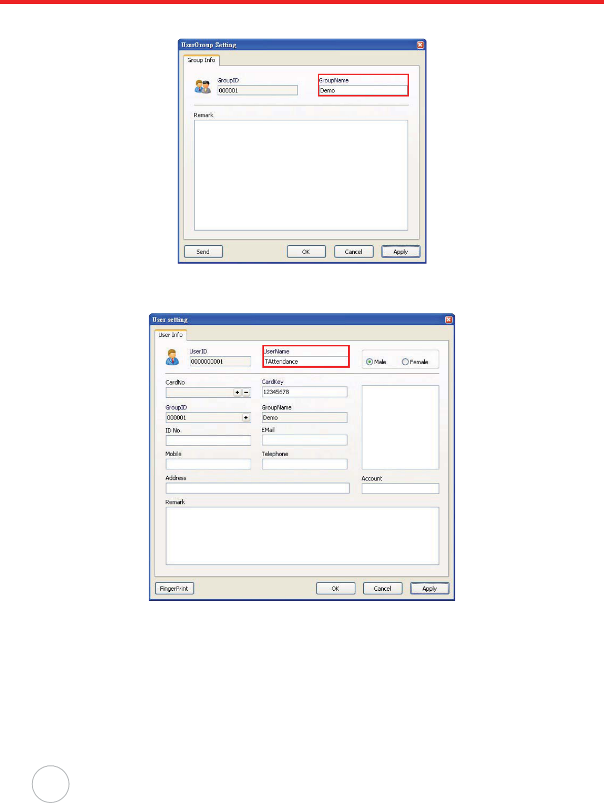
12. Right-click All Groups, and click Append o Group to add a new user group. The User Group
Setting window appears.
22
Copyright 2009 Unitech Electronics Co., Ltd. All rights reserved. Unitech is a registered trademark of Unitech Electronics Co., Ltd.
13. Enter the user group name (for example, DEMO). Click Apply, and then OK to return to the
User Group Setting window.
14. Right-click the desired group (for example, DEMO), and click Append oEntity to add a new
user. The User setting window appears.
15. Enter the user name (for example, TAttendance) in the UserName field.
16. Inside the CardNo field, click +. The Card Setting window appears.
Chapter 4 Advanced Setting
23
17. Input the card number in the Card No. field. Click Apply, and then OK to return to the User set-
ting window.
NOTE: See General Settings on page 12 to acquire the card number.
18. Click OK to return to the User Group Setting window.
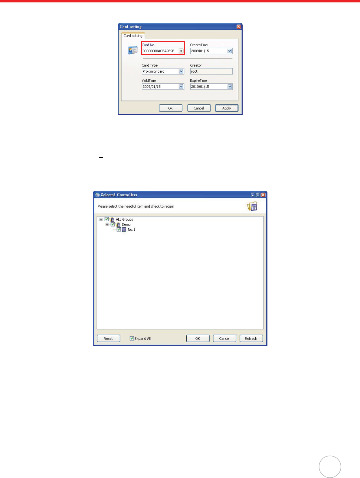
19. Click Permit(P)o Permit Management.
20. Select the desired user group (for example, DEMO), and click Setting on the toolbar. The
Selected Controllers window appears.
21. Select the desired controllers (for example, No.1 DEMO), and click OK to return to the Janitor-
Lite - [Permit Management] window.
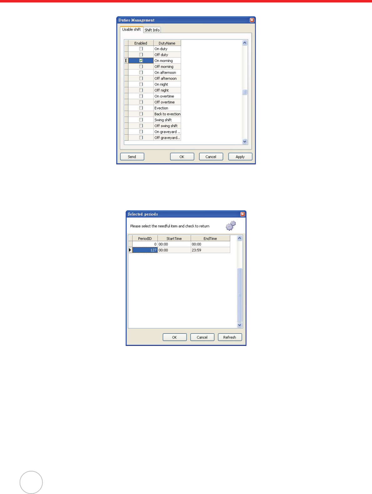
22. Click Attendance o Duty Management.
24
Copyright 2009 Unitech Electronics Co., Ltd. All rights reserved. Unitech is a registered trademark of Unitech Electronics Co., Ltd.
23. Under the Usable Shift tab, select a desired work shift (for example, On Morning).
24. Under the Shift Info tab, select a desired weekday from the drop down menu (for example,
Thursday).
25. Double-click +inside the PeriodID field. The Selected periods window appears.
26. Click a desired time period (for example, PeriodID 127) to set for 24 hours of access in this
weekday. Click OK to return to the Duty Management window.
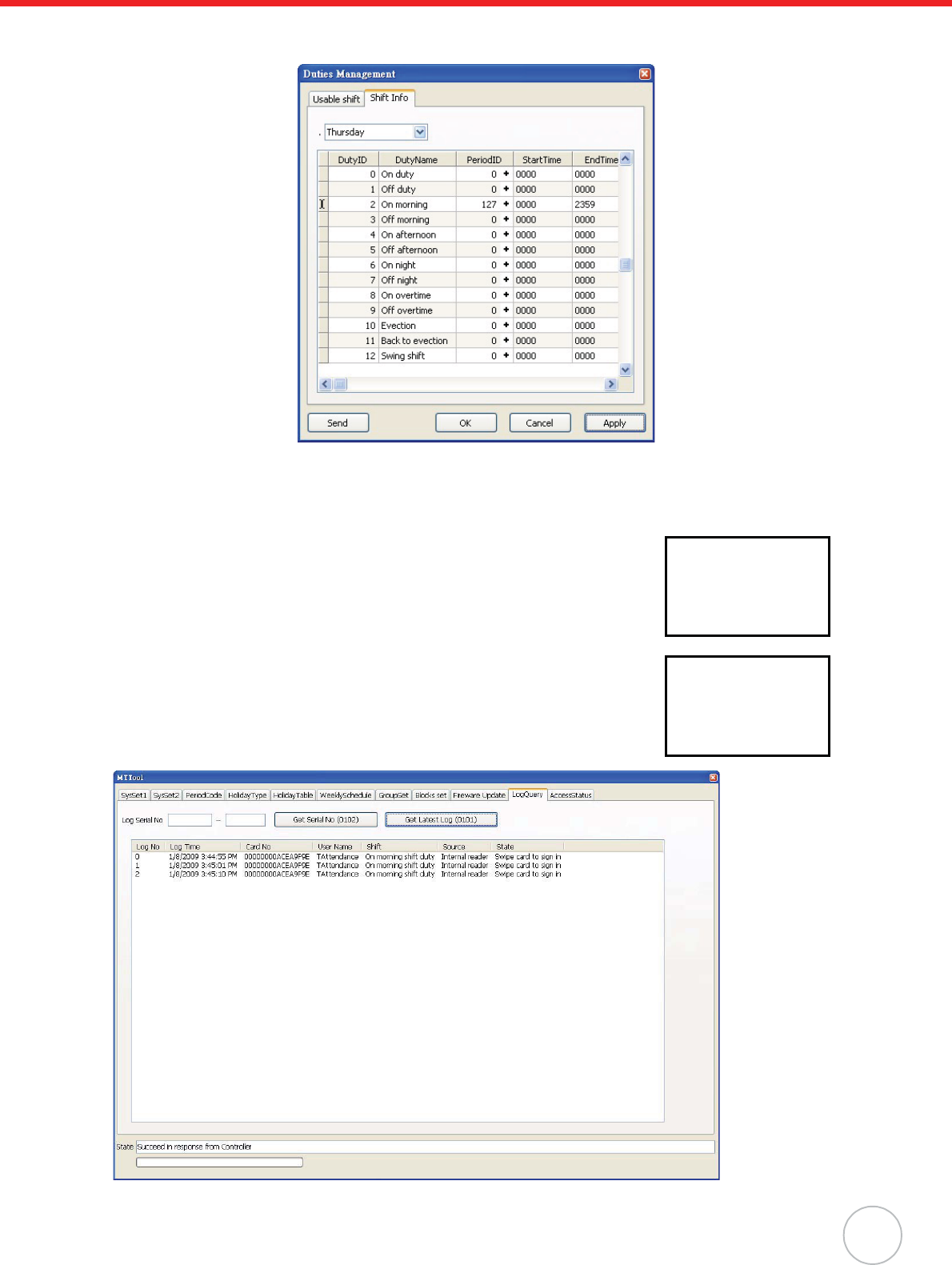
Chapter 4 Advanced Setting
25
27. Click Apply oSend to immediately send the command to the controller. A window appears
with the message Setting Successfully.
28. Click OK to exit.
Scenario I - Swipe Card to Clock In
Swipe a card on the Proximity Reader while the standby screen on MT180
displays the desired work shift name (for example, morning shift work).
The user name (for example, TAttendance) and the clock in time display
onscreen.
In MTTool, under the LogQuery tab, click Get Latest Log. Find the atten-
dance record.
XX:XX:XX
Sign in
morning shift work
TAttendance
XX:XX:XX
Recorded
26
Copyright 2009 Unitech Electronics Co., Ltd. All rights reserved. Unitech is a registered trademark of Unitech Electronics Co., Ltd.
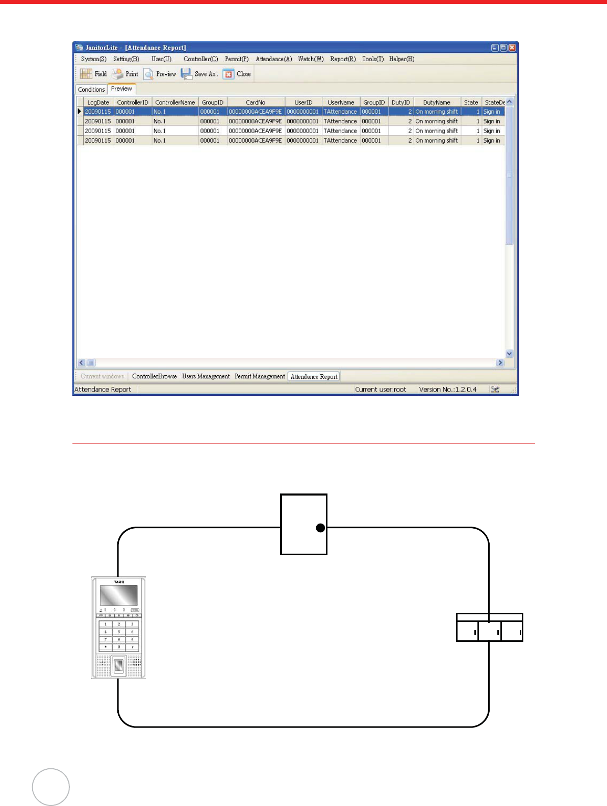
In JanitorLite, click Report o Attendance Report. Under the Conditions tab, filter the user, controller,
and date, and click OK. The attendance record displays under the Preview tab.
Security Operation
To prevent unauthorized access, MT180 can setup a secure area which is enclosed by the terminal and
surrounding senors. The following security system architecture demonstrates a closed-loop connection
through the terminal, door sensor and window sensor.
MT180.
Door Sensor.
Window Sensor.
Closed-Loop.
Chapter 4 Advanced Setting
27
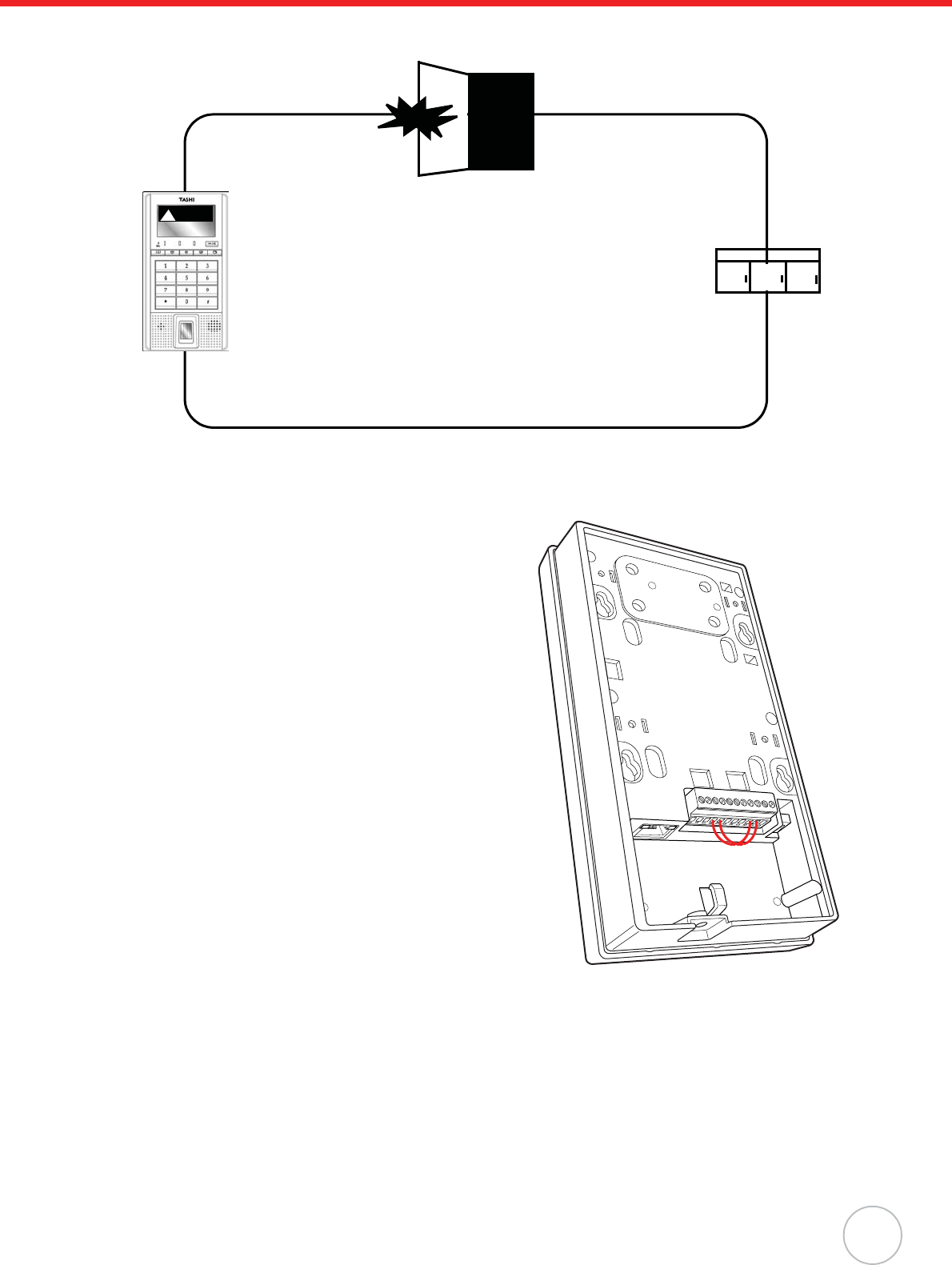
The following security system architecture demonstrates an open-loop system, which disconnects the
door sensor and triggers MT180’s security alarm.
It is possible to place or lift security bans by the same proximity card used for access control or time
attendance mode. Utilize MTTool to optimize security settings through the following:
1. Connect Pin 4 (CHECK) to Pin 9 (GND).
2. Connect Pin 5 (SAFE) to Pin 10 (GND).
3. Set MT180 and the computer on the same subnet
network.
4. Execute MTTool on the computer.
MT180
in Alarm Status.
Door Sensor.
Window Sensor.
Open-Loop.
Alarm
!
28
Copyright 2009 Unitech Electronics Co., Ltd. All rights reserved. Unitech is a registered trademark of Unitech Electronics Co., Ltd.
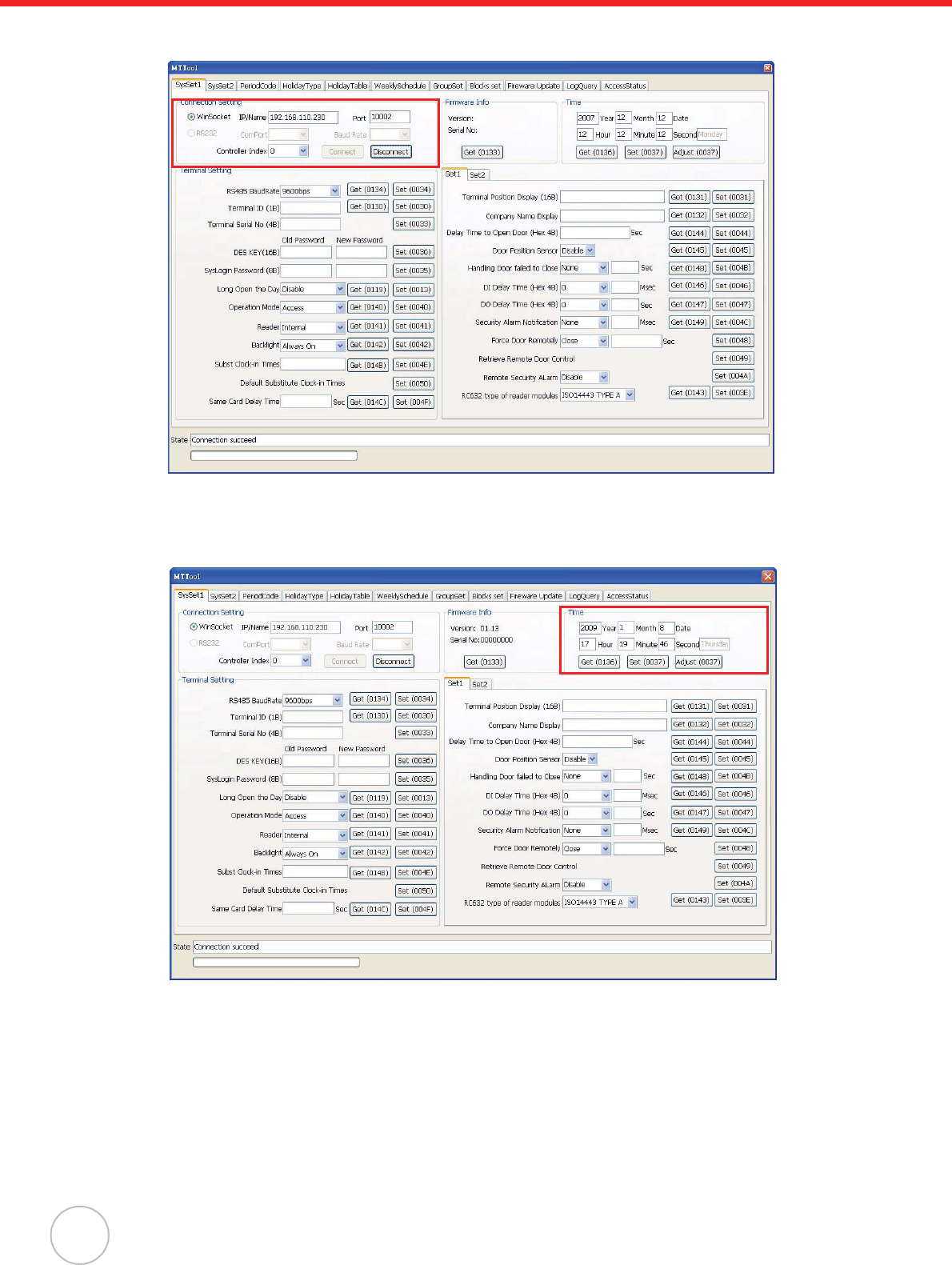
5. In MTTool, under the SysSet1 tab, select WinSocket and input the IP address (for example,
192.168.110.230). Click Connect.
NOTE: See Advanced Settings on page 13 to set MT180’s IP address.
6. Click Adjust to synchronize the system time with the computer.
7. Click Get to double check the date and time set on MT180.
Chapter 4 Advanced Setting
29
8. In the Set1 tab, select Buzzer from the System Alarm Notification drop down menu. Click
Set.
9. Under the SysSet2 tab in the Card Setting box, input the card number, user name, user num-
ber, group number and etc. Click Add a Card No.

30
Copyright 2009 Unitech Electronics Co., Ltd. All rights reserved. Unitech is a registered trademark of Unitech Electronics Co., Ltd.
10. Under the WeeklySchedule tab, select Weekly Security Schedule.
11. Double-click on a desired table cell (for example, row 1 / column Thursday). The Period Code
window appears.
12. Click a desired time period (for example, 00002359) to set for 24 hours in this weekday. Click
OK.
Chapter 4 Advanced Setting
31
13. The period code 7F displays on the table cell. Click Set.
14. Under the GroupSet tab, select the desired group (0).
15. Double-click on a desired table cell (row 1 / column Thursday). The Period Code window
appears.
32
Copyright 2009 Unitech Electronics Co., Ltd. All rights reserved. Unitech is a registered trademark of Unitech Electronics Co., Ltd.
16. Click a desired time period (for example, 00002359) to set for 24 hours in this weekday. Click
OK. The period code 7F displays on the table cell.
17. In the Security Mode Control box, select Enable/ Disable Security Mode.
18. Click Set Group Info.
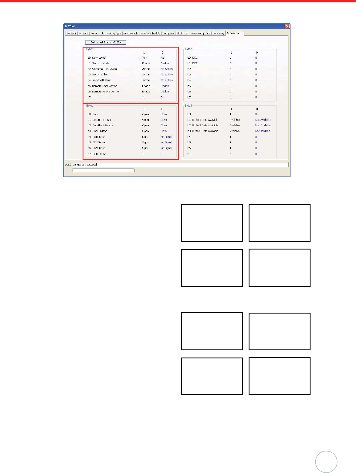
19. Under the AccessStatus tab, click Get Latest Status.
20. Check the Byte0 box values, Security Mode highlights Enable in blue.
Chapter 4 Advanced Setting
33
21. Check the Byte1 box values, Door highlights Close in blue, and Security Trigger highlights
Close in blue.
Scenario I - Place Security Ban
Press À to enter the security setting screen, while
in standby status. The current security status,
SecuredRelease displays onscreen.
Swipe the card on the Proximity Reader, and the
security status switches to Secured.SecuredSta-
tus displays on the standby screen indicating a
security ban.
Scenario II - Lift Security Ban
Press À to enter the security setting screen while
in standby status and SecuredStatus displays
onscreen. The current security status, Secured
displays onscreen.
Swipe the card on the Proximity Reader, and the
security status switches to SecuredRelease.
SecuredStatus disappears on the standby screen
indicating the security ban is lifted.
SecuredRelease
PressCard
Unitech
XX:XX:XX
2009.1.8 Thur.
Secured
PressCard
Unitech
XX:XX:XX
SecuredStatus...
Secured
PressCard
Unitech
XX:XX:XX
SecuredStatus...
SecuredRelease
PressCard
Unitech
XX:XX:XX
2009.1.8 Thur.
34
Copyright 2009 Unitech Electronics Co., Ltd. All rights reserved. Unitech is a registered trademark of Unitech Electronics Co., Ltd.
Scenario III - Trigger Security Alarm
Disconnect Pin 5 (SAFE) to Pin 10 (GND) to
loosen the loop while the security ban is set. The
loosened loop triggers the security alarm, and
SecuredAlarm displays on the standby screen.
Press À to enter the security setting screen. Th
current security status, Secured displays
onscreen. Swipe the card on the Proximity Reader,
the security status switches to SecuredRelease
indicating that the security ban is lifted.
SecuredAlarm disappears on the standby screen.
Check the loop and reconnect Pin 5 (SAFE) to Pin
10 (GND).
Anti-Pass Back Setting
Enforce Anti-Pass Back to control the entrance/exit behavior and prevent unauthorized access. Utilize
MTTool to prohibit same card reentry and re-exit through the same door.
1. Connect a secondary reader to MT180 via RS232 Drive.
NOTE: While MT180 serves as an internal reader, the secondary reader is the external reader.
Ensure the card type is compatible with the internal/external reader.
2. Set MT180 and the computer on the same subnet network.
3. Execute MTTool on the computer.
! Alarm
SecuredAlarm
!
Unitech
XX:XX:XX
SecuredStatus...
SecuredRelease
PressCard
Secured
PressCard
Unitech
XX:XX:XX
2009.1.8 Thur.
RS232 Drive
Chapter 4 Advanced Setting
35
4. In MTTool, under the SysSet1 tab, select WinSocket and input the IP address (for example,
192.168.110.230). Click Connect.
NOTE: See Advanced Settings on page 13 to set MT180’s IP address.
5. Click Adjust to synchronize the system time with the computer.
6. Click Get to double check the date and time set on MT180.
36
Copyright 2009 Unitech Electronics Co., Ltd. All rights reserved. Unitech is a registered trademark of Unitech Electronics Co., Ltd.
7. In the Terminal Setting box, select Internal+External from the Reader drop-down menu. Click
Set.
8. Under the SysSet2 tab, in the Card Setting box, input the card number, user name, user num-
ber, group number and etc. Click Add a Card No.
Chapter 4 Advanced Setting
37
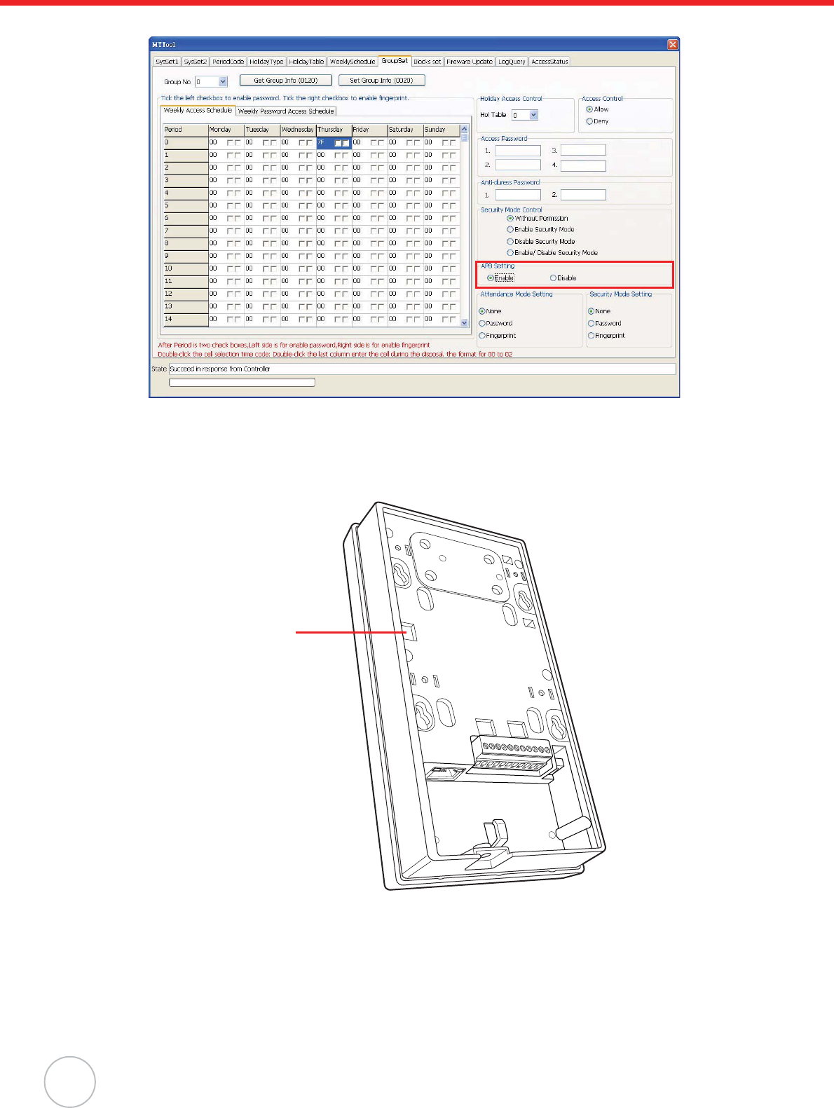
9. Under the GroupSet tab, select the desired group (0).
10. Double-click on a desired table cell (row 1 / column Thursday). The Period Code window
appears.
11. Click a desired time period (for example, 00002359) to set for 24 hours of access in this week-
day. Click OK. The period code 7F displays on the table cell.
38
Copyright 2009 Unitech Electronics Co., Ltd. All rights reserved. Unitech is a registered trademark of Unitech Electronics Co., Ltd.
12. In the APB Setting box, select Enable.
13. Click Set Group Info.
Utilize JanitorLite to prohibit same card reentry and re-exit through the same door.
1. Connect a secondary reader to MT180 via Drive RS232.
NOTE: While MT180 serves as an internal reader, the secondary reader is the external reader.
Ensure the card type is compatible with the internal/external reader.
2. Set MT180 and the computer on the same subnet network.
NOTE: Switch the controller operation mode to be Access, and synchronize the date and time
in MTTool.
RS232 Drive
Chapter 4 Advanced Setting
39
3. Execute JanitorLite on the computer.
4. Click Controller(C)o Controller Management.
5. Right-click All Groups, and click Append o Group to add a new controller group. The Con-
troller Group Management window appears.
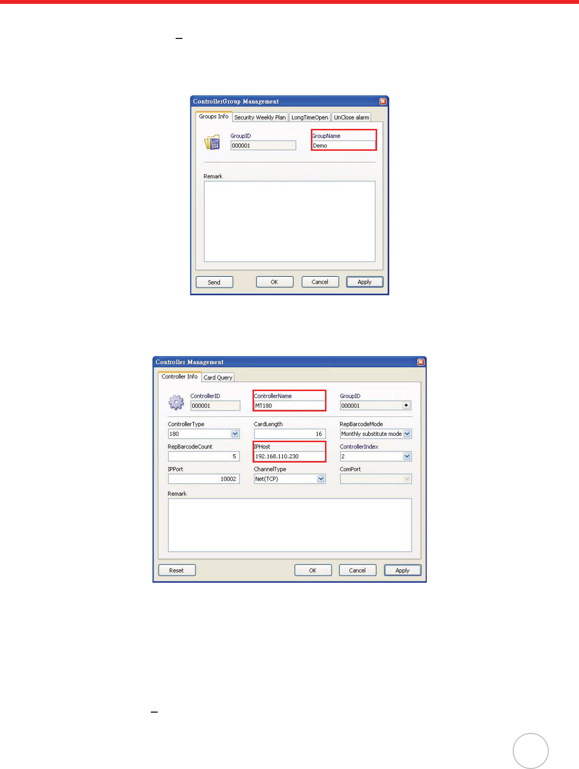
6. Enter the controller group name (for example, Demo). Click Apply oOK to return to the Con-
troller Group Management window.
7. Right-click the desired group (Demo), and click Append o Entity to add a new controller. The
Controller Management window appears.
8. In the ControllerName field, enter the controller name (for example, MT180).
9. In the IPHost field, input the controller’s IP address (192.168.110.230). Click Apply.
10. Click Reset to reset data in this controller. A window appears, asking to reset. Click Yes. MT180
screen displays messages Please wait! EraseFingerInfo., Please wait! Erase Log... and
Please wait! EraseCardInfo. MT180 returns to the standby status when complete.
NOTE: Alternatively, reset data under the SysSet2 tab in MTTool. In the Delete all field, select
to delete all cards, logs, fingerprints, and click Delete. In the Shift Setting field, click
Clear All oSet.
11. Click OK to return to the Controller Group Management window.
12. Click User(U)o User Management.
40
Copyright 2009 Unitech Electronics Co., Ltd. All rights reserved. Unitech is a registered trademark of Unitech Electronics Co., Ltd.
13. Right-click All Groups, and click Append o Group to add a new user group. The UserGroup
Setting window appears.
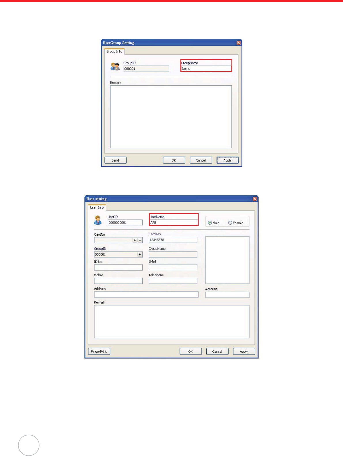
14. In the GroupName field, enter the user group name (Demo). Click Apply oOK to return to
the JanitorLite - [Users Management] window.
15. Right-click the desired group (Demo), and click Append oEntity to add a new user. The User
Setting window appears.
16. In the UserName field, enter the user name (for example, APB).
17. Inside the CardNo field, click +. The Card setting window appears.
Chapter 4 Advanced Setting
41
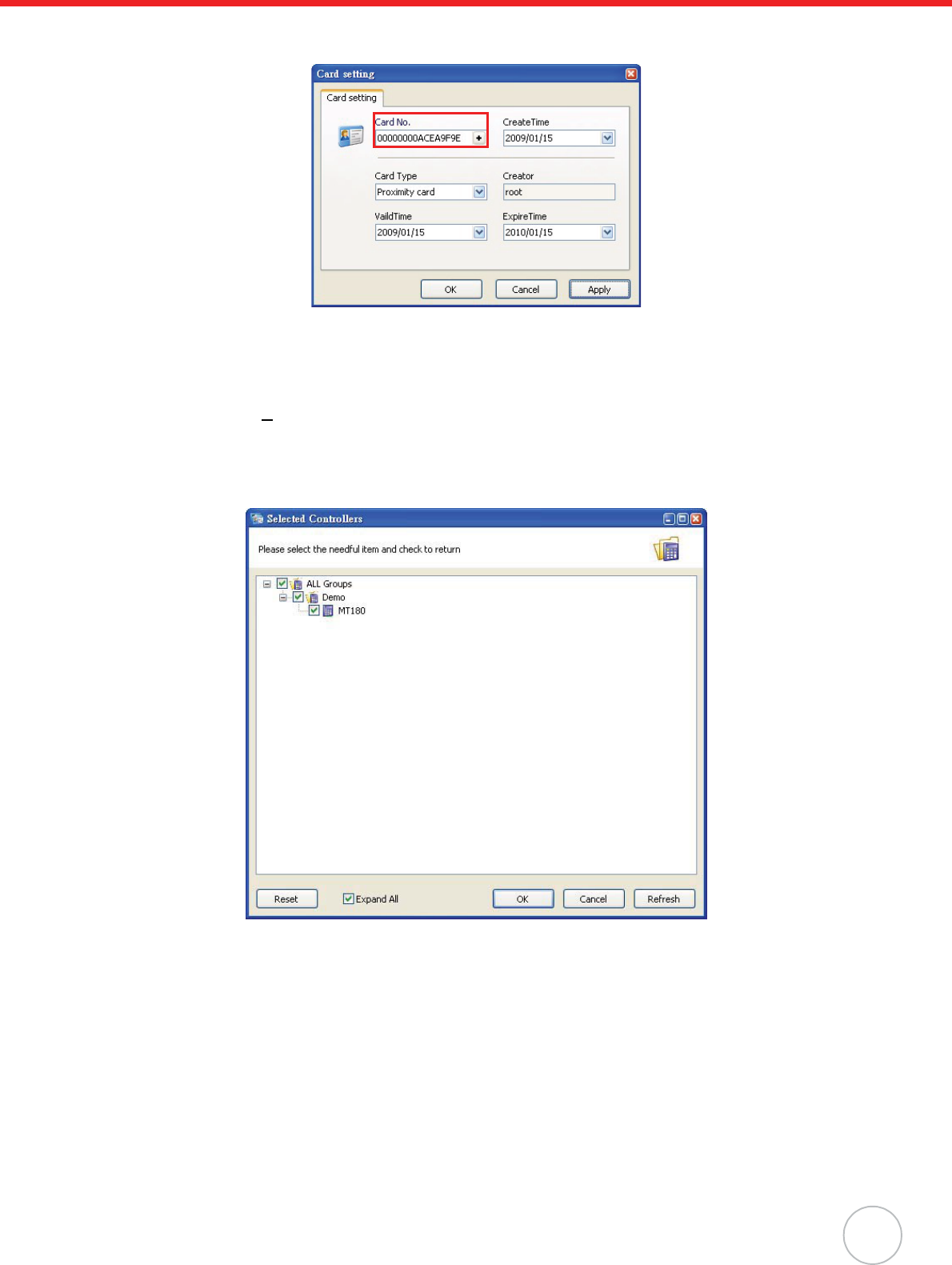
18. Input the card number in the Card No. field. Click Apply oOK to return to the User setting
window.
NOTE: See General Settings on page 12 to acquire the card number.
19. Click OK to return to the JanitorLite - [Users Management] window.
20. Click Permit(P)o Permit Management.
21. Select the desired user group (Demo), and click Setting on the toolbar. The Selected Control-
lers window appears.
22. Select the desired controllers (MT180 and Demo), and click OK to return to the JanitorLite -
[Permit Management] window.
23. Double-click the desired user group (Demo). The UserGroup Setting window appears.
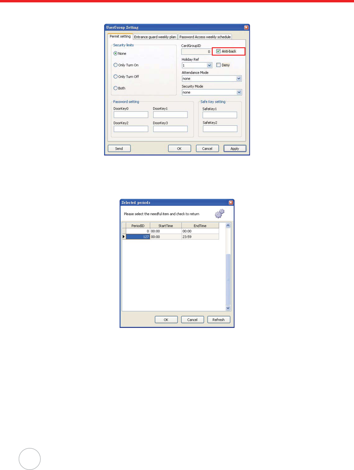
42
Copyright 2009 Unitech Electronics Co., Ltd. All rights reserved. Unitech is a registered trademark of Unitech Electronics Co., Ltd.
24. Under the Permit Setting tab, check Anti-back. Click Apply oSend to immediately send this
command to the controller. A window appears with the message Setting Successfully.
25. Under the Entrance guard weekly plan tab, select a desired weekday from the drop down
menu.
26. Inside the PeriodID field, double-click +. The Selected periods window appears.
27. Click a desired time period (for example, PeriodID 127) to set for 24 hours of access in this
weekday, and click OK.
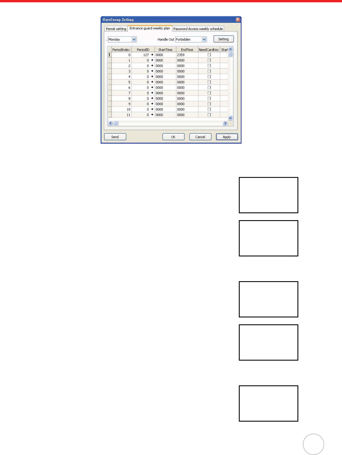
Chapter 4 Advanced Setting
43
28. Click Apply oSend to send the command to the controller immediately.
29. Click OK to return to the JanitorLite - [Permit Management] window.
Scenario I - Normal Entrance and Exit
Swipe the card on the internal reader, while in standby status. Entrance
with the user name APB displays on the standby screen indicating that
reentry is not allowed.
Swipe the card on the external reader, Exit with the user name APB dis-
plays on the standby screen indicating that re-exiting is not allowed.
Scenario II - Re-Entering
Swipe the card on the internal reader, Entrance with the user name APB
displays on the standby screen.
Swipe the card again on the internal reader, Re-Entering with the user
name APB displays on the standby screen indicating that reentry occurred.
Scenario III - Re-Exiting
Swipe the card on the external reader, Exit with the user name APB dis-
plays on the standby screen.
Unitech
APB
Entrance
2009.1.8 Thur.
Unitech
APB
Exit
2009.1.8 Thur.
Unitech
APB
Entrance
2009.1.8 Thur.
Unitech
APB
Re-Entering
2009.1.8 Thur.
Unitech
APB
Exit
2009.1.8 Thur.
44
Copyright 2009 Unitech Electronics Co., Ltd. All rights reserved. Unitech is a registered trademark of Unitech Electronics Co., Ltd.
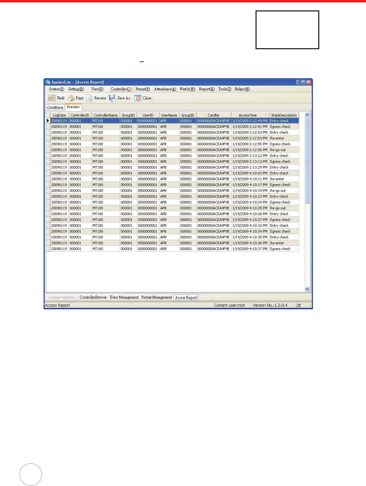
Swipe the card again on the external reader, Re-Exiting with the user name
APB displays on the standby screen indicating that re-exiting occured.
If utilizing JanitorLite, Click Report(R)o Access Report. Under the Con-
ditions tab, filter the user, controller, and date, and click OK. The access
record displays under the Preview tab.
Unitech
APB
Re-Exiting
2009.1.8 Thur.

45
Appendix A
System Specification
Processing/Memory CPU ARM7TDMI-S
Memory 8MB External Flash
Display 128 × 64 Pixel COG/FSTN LCD with White Backlight
Keypad 18-key, Including Talk Key, Function Key and Numeric Key
Communication Ethernet10/100M, RS485 and Optional DECT Voice
I/O Digital Inputs (3): Door Open, Door Position and Security Trigger
Relay (2): Electrical Door Lock and Alarm
I/O Expansion RS232 Drive (1) - Secondary Reader
Digital Inputs (3)
Digital Outputs (3)
Proximity Reader
(Optional)
EM, 125kHz
HID, 125kHz
MiFare, 13.56MHz (ISO 14443A/B, ISO 15693)
Power Supply DC 12V, 2.0A
Enclosure Weight 410 g. (14.46 oz.)
Dimension 188.09mmL X 38.67mmH X 99.94mmW
(7.4”L X 1.5”H X 3.9”W)
Environmental Operating Temperature -10ºC - 50ºC (14ºF - 122ºF)
Storage Temperature -20ºC - 60ºC (-4ºF - 140ºF)
Relative Humidity 35% - 95%
Certification CE, FCC, NCC, CCC, RoHS compliant
Software JanitorLite, MTTool, Communication SDK
Accessories On Wall Mounting Kit

46
Appendix B
Worldwide Support
Region Website
Global Operation Center www.unitech-adc.com
Unitech Asia Pacific & Middle www.unitech-utp.com.tw
Greater China Division www.unitech-sbd.com
Unitech Japan www.unitech-japan.co.jp
Unitech America www.ute.com
Unitech Latin America www.latin.ute.com
Unitech Europe www.unitech-europe.nl