Unitech Electronics MT700EF Multi-functional T&A; Terminal User Manual part II
Unitech Electronics Co., Ltd. Multi-functional T&A; Terminal part II
Contents
- 1. User Manual_part I
- 2. User Manual_part II
User Manual_part II
2
NOTE: The MT700’s display is shipped with a transparent protection film that has been pasted
onto the surface of touch panel of the MT700 for protecting the top cover and touch
panel. Before using the MT700, tear out the protective film.
If MT700 is provided with RFID reader, you will see the RFID reader logo on the
front panel of MT700.
DO NOT wipe the MT700 with any chemical cleansing agent! We recommend the
usage of clean water or soft cloth for display panel/eyeglasses to clean the machine.
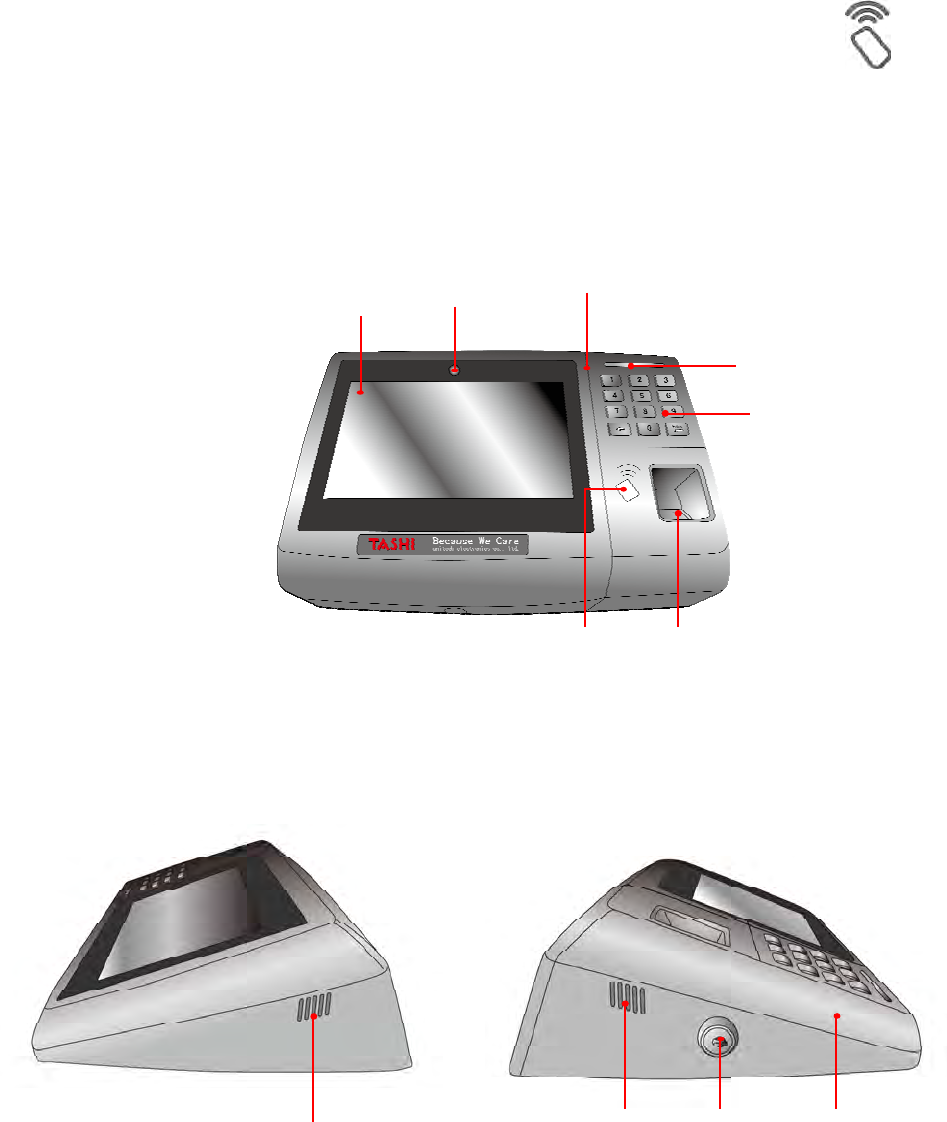
The following sections describe the main components and features of the M700.
Front View
Side View
Left
Right
Touch Screen
Camera
Microphone
LED
Keypad
Finger
Printer
RFID
Speaker
Lock
Reset
Speaker
3
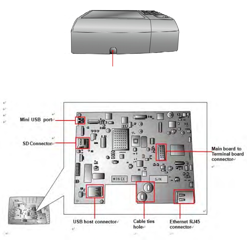
Bottom View
Front Main Board
The Main board can be access via unlocking the right side lock of the MT700 and removing the
back steel plate.
Cable hole
4
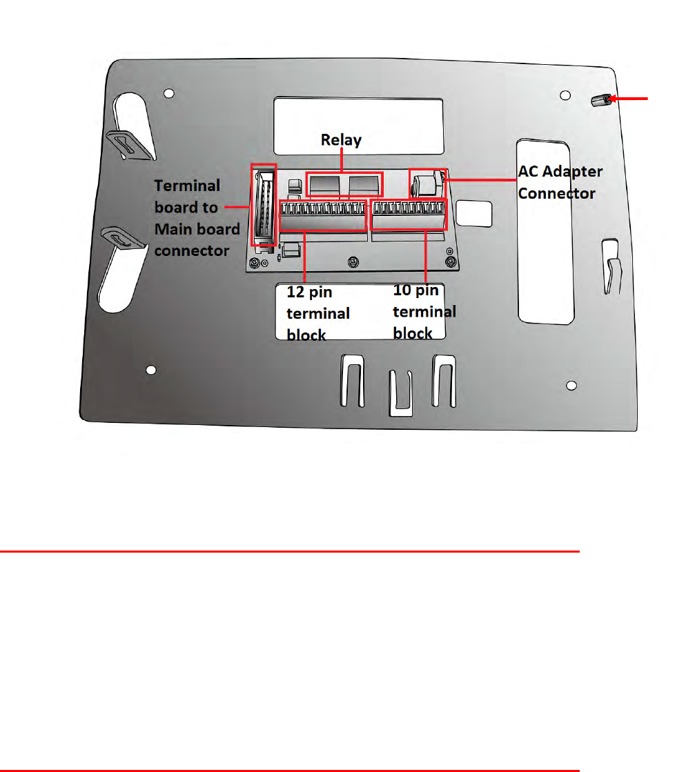
Back Terminal Board
The terminal board can be access via unlocking the right side lock of the MT700 and removing
the back steel plate.
Setting up the MT700
Connecting Power
Connect power to the MT700 through the following instruction: Plug the Power Adapter Cable
into the MT700’s DC input jack and then connect the other end of the Power Adapter into an
electrical outlet.
Powering On the MT700
The MT700 automatically powers on when the Power Adapter plugs into an external power
source. The MT700 welcome screen appears.
Using the MT700 for the First Time
Using the Touch-screen
1. Tap the screen to choose a menu option.
2. Double tap to open programs.
3. Use the Windows CE Keyboard to type letters or numbers into a data field or on a form.
Magnetic
Hall
sensor
5
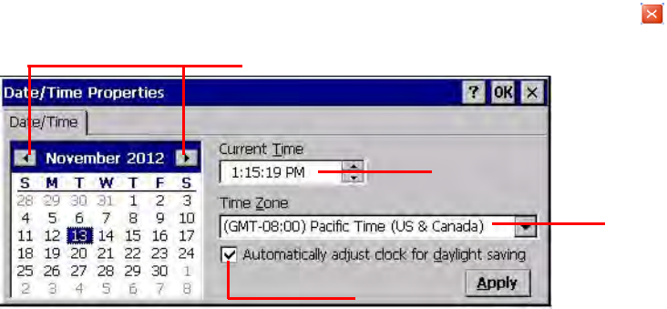
Setting the Date and Time
In the Date/Time Properties window, touch the screen to select the current date/time, time zone
and daylight saving time option.
Tap the Left or Right arrows to scroll through the desired year and month, or directly tap
the year or month to change the setting.
Tap on the Hr/Min/Sec AM/PM to input the Hr/Min/Sec to set the time.
Tap the arrow and set the correct time zone from the drop-down menu.
Check the box to enable Windows to automatically adjust for day-light saving time.
Tap Apply to save the settings and exit the Date/Time Properties dialog, or tap to exit
without saving.
Date Setting
Time Setting
Time Zone Setting
Daylight Saving
6
Basic Operation
Chapter 2
On-screen virtual Keyboard
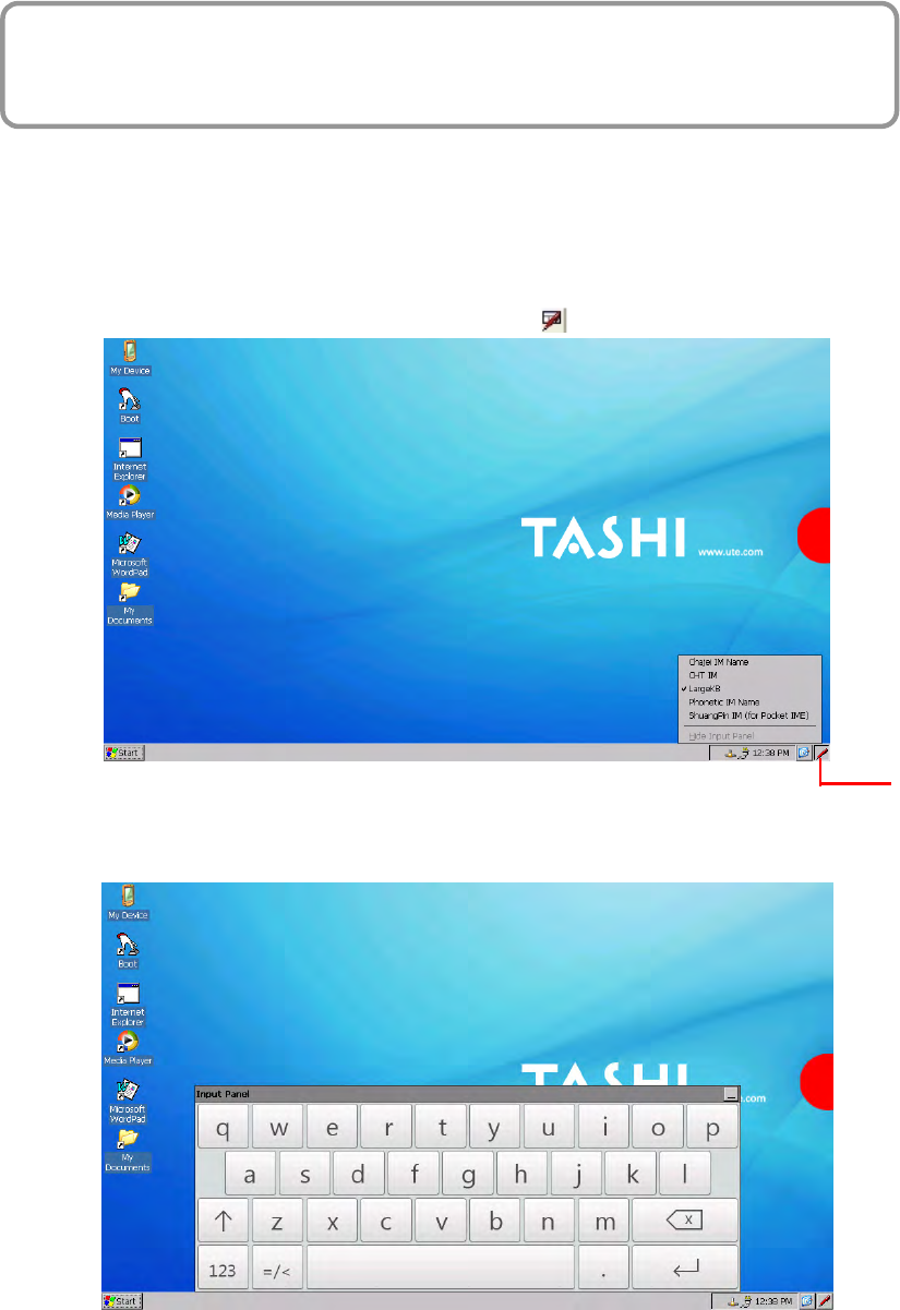
Windows CE features on-screen virtual keyboard that simulates all functions and behaviors of
physical PC keyboard.
To launch the on-screen virtual keyboard, please tap LargeKB.
Entering Characters
Entering alphabetic and numeric characters on the MT700 is the same as character input on a
standard PC keyboard. Tap the onscreen button corresponding to the desired character.
Keyboard Icon
7
Moving the Keyboard
Tap the title bar and drag the keyboard to a desired location.
Closing the Keyboard
Tap the keyboard icon Hide Input Panel to close the Windows CE keyboard.
RFID Reader (Optional)
If the MT700 is with built-in RFID reader, you will see the RFID reader logo on the front
panel of MT700. The MT700 features a standard RFID reader, which is compatible with
13.56MHz MiFare cards.
RFID Card Verification
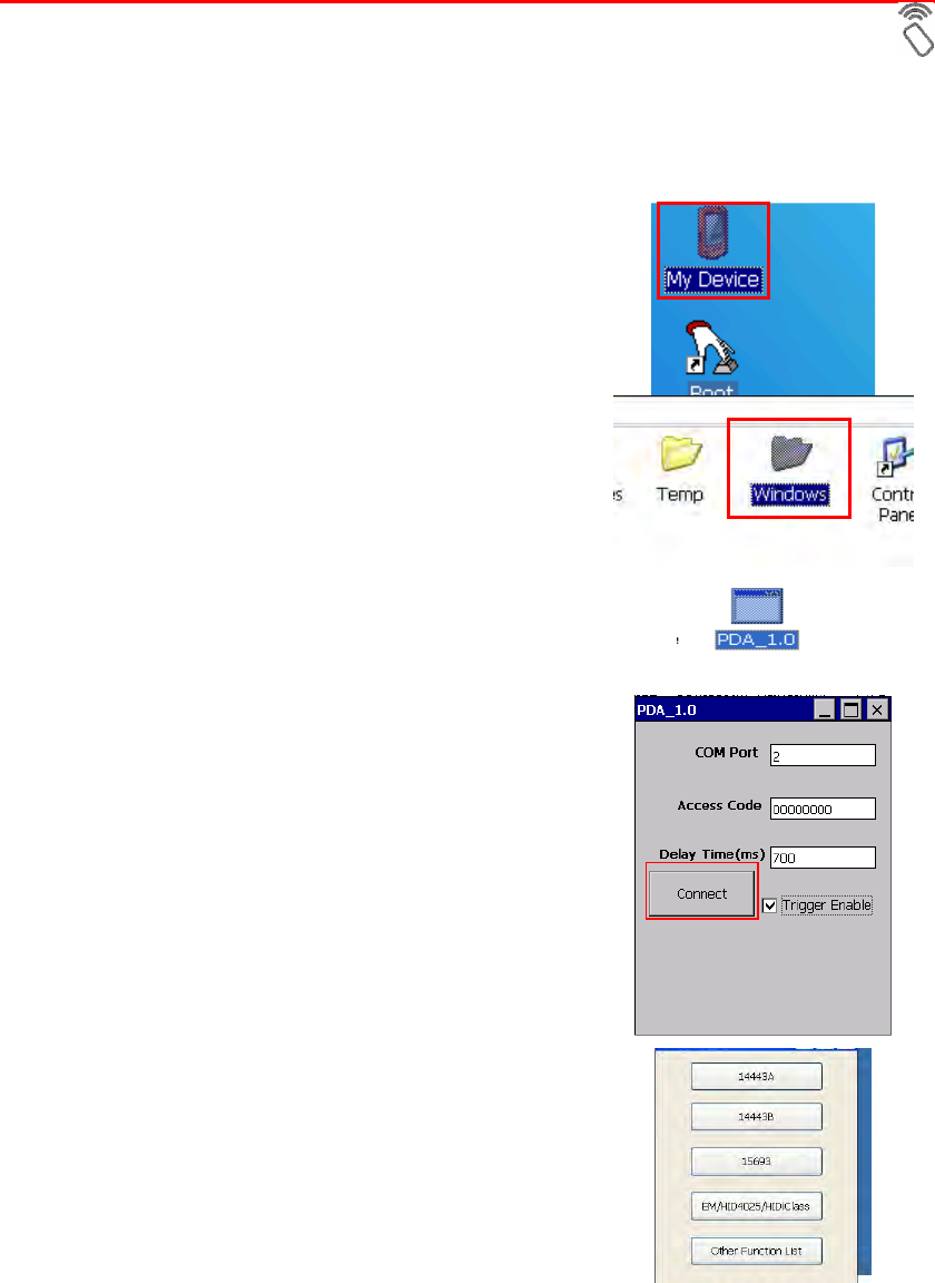
The MT700 has built-in demo programs that allow RFID card verifications.
1. Double-tap the My Device icon on the
Windows CE desktop.
2. Tap Windows.
3. Double-tap PDA_1.0 to open the demo
program.
4. Set the COM Port: field at 2. Tap Connect.
5. Choose a card type to activate the demo
test program.
8
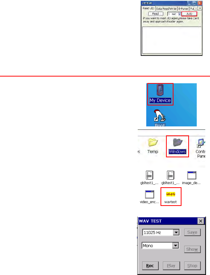
6. Tap Auto and bring the RFID card close to
the sensor. The code will display on the field
below.
7. Tap Stop to end the reading.
Audio Input/Output
An audio demo program will test the audio input (recording) and output (playback).
1. Double tap My Device on the Windows CE
desktop.
2. Double-tap Windows.
3. Double-tap wavtest to open the demo
program.
4. Do one of the following:
-- Tap Rec to record the voice.
-- Tap Stop to finish recording.
-- Tap Play to listen to the recording.
9
Built-in Camera
The MT700 has a built-in 2.0 megapixel camera which provides the following extra
functionality:
Enables users to capture still pictures when a card is being read
Checks attendant time with a photo image
Records video continuously
Functions as an audio/video intercom
Additionally, facial recognition can be incorporated using third party software.
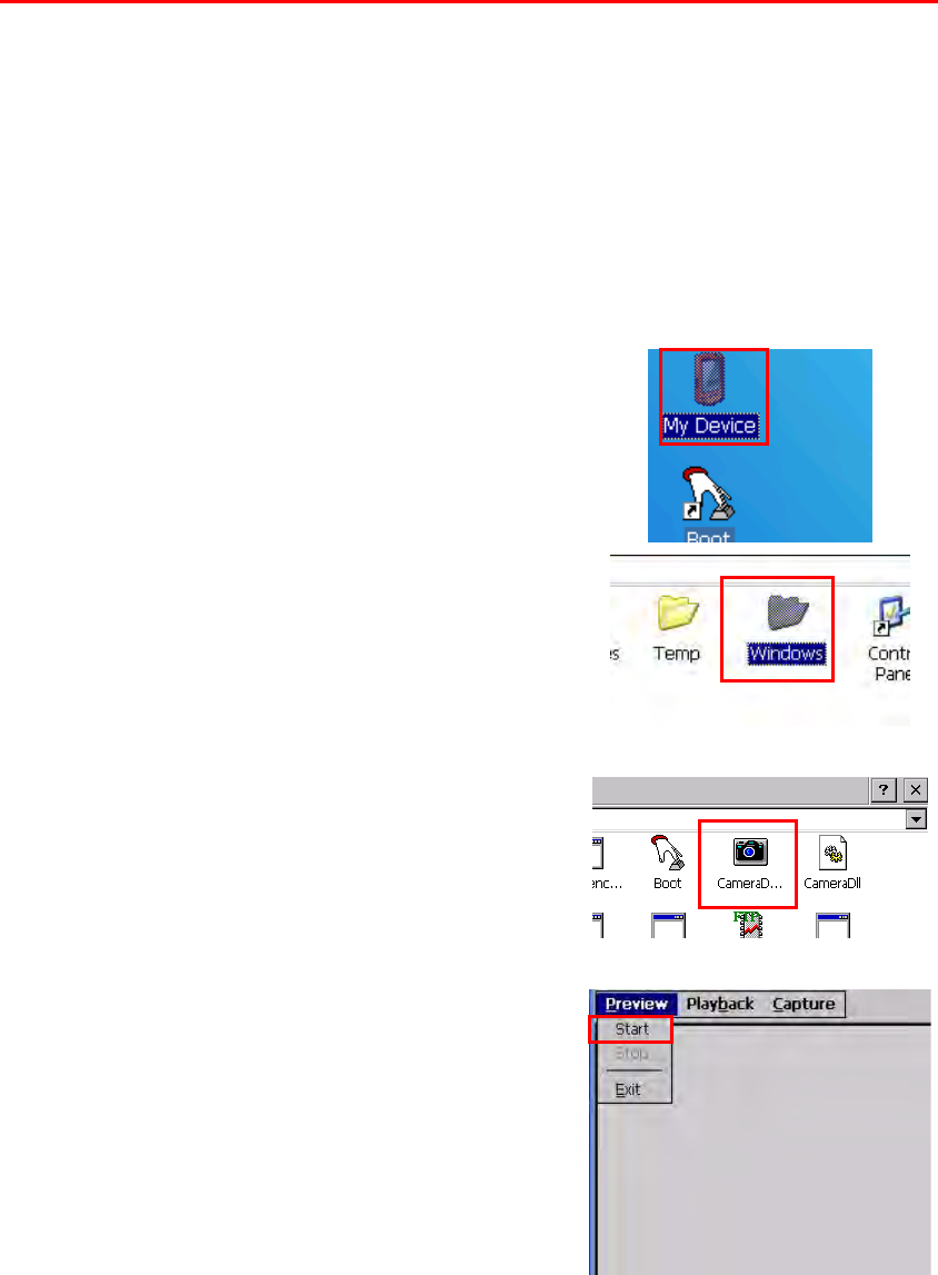
The MT700 has a demo program that enables users to capture a still picture with a card
number and time stamp when a card is read.
To start the camera demo:
1. Double-tap the My Device icon on the
Windows CE desktop.
2. Double-tap the Windows folder.
3. Double-tap CameraDemo to open the
program. The testing program is displayed.
4. Tap Preview → Start.
A continuous image is displayed enabling users to capture and playback video.
10
Tools/Utilities/Applications
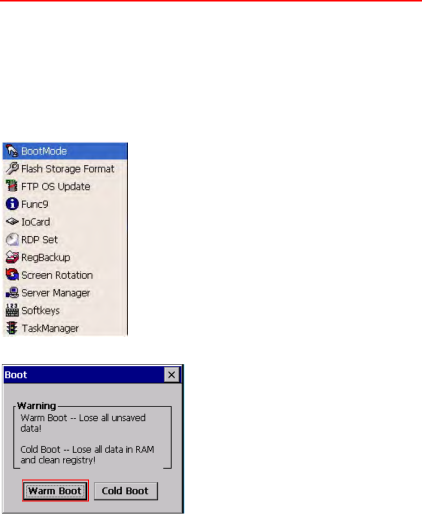
BootMode
Path: Start Menu/Programs/Utilities/Boot Mode
This tool allows you to perform warm boot or cold boot.
Warm Boot
1. Select Start Menu -> Programs -> Utilities -> Bootmode
2. Tap “Warm Boot”. The system will be warm started.
11
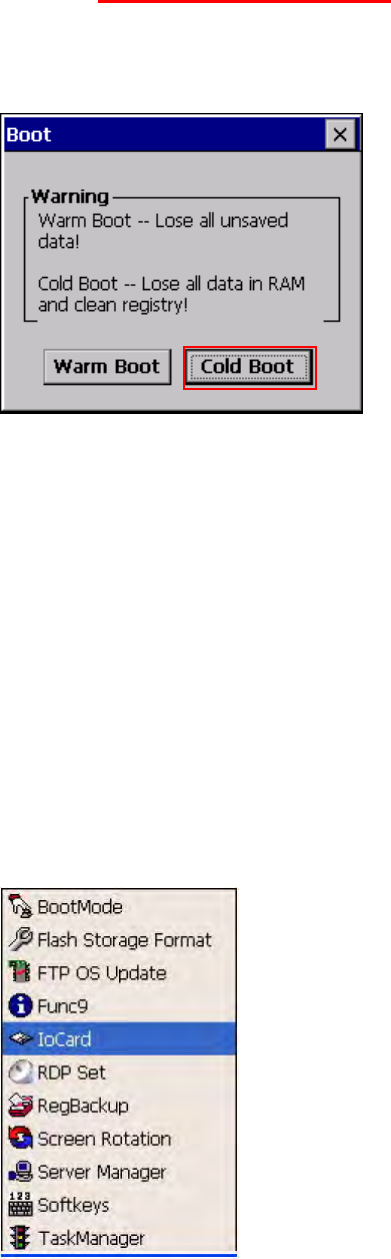
Cold Boot
Caution: Backup your data first!
1. Tap “BootMode”, and Tap “Cold Boot”. Then confirm the choice by selecting
YES when program asked to reconfirm the command.
2. The terminal will be cold started.
3. Calibrate the screen according to the instruction displayed, and tap the screen
anywhere again once the calibration is completed to continue.
4. Set the date and time, press OK.
I/O Card Control
Path: Start Menu/Programs/Utilities/IO Card
This tool allows you enable or disable CF slot whenever it is necessary. Once you
disable the slot, the card in that slot will not work until you enable the slot again.
1. Select Start Menu ->Programs -> Utilities -> IO Card
2. You may choose to enable or disable the card from this tool. Once you selected
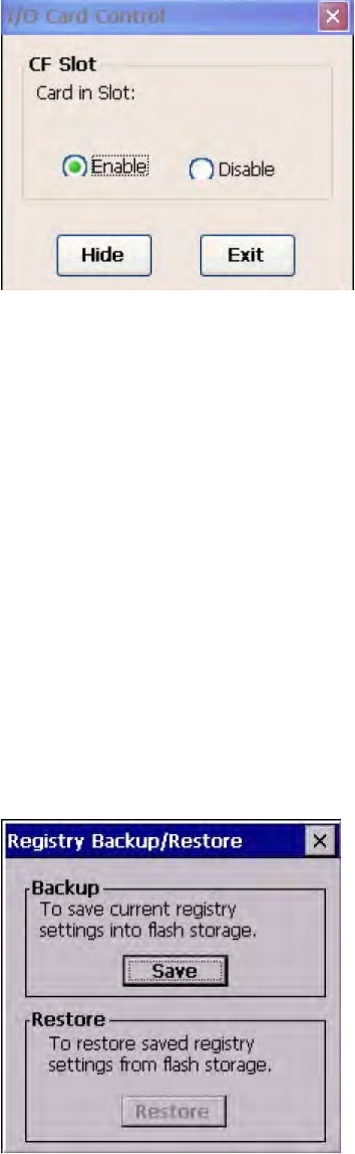
12
disable, the card will no longer be detected unless it is enabled again. Tap “Enable”
to enable the card.
3. Tap “Hide” to hide I/O Card Control window.
4. Tap “Exit” to exit I/O card control.
The setting is kept after suspend and power on, however, after warm start/cold start,
the setting will be resumed to default value (which is “Enable”)
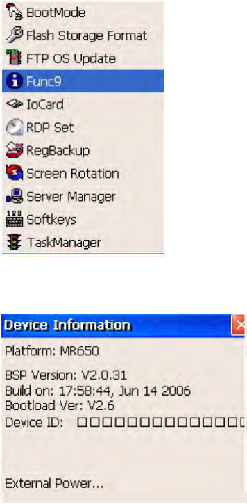
Registry Backup
Path: Start Menu/Programs/Utilities/RegBackup
This tool allows you to save the current registry or reset to factory default.
1. Select Start Menu -> Programs -> Utilities -> RegBackup.
2. Tap “Save” to save current registry settings.
3. Or tap “Restore” to reset registry to factory default. Terminal will be warm started.
(Note that “Restore” button is grey out if the registry setting was not saved before)
13
Func 9
Path: Start Menu/Programs/Utilities/Func9
This tool displays the general information of the terminal such as platform, firmware
version, device ID etc.
1. Select Start Menu -> Programs -> Utilities -> Func9
2. Device information is shown as below:
Server Manager
Path: Start Menu/Programs/Utilities/ServerManager
Server Manager is a tool for the user to manager the NTLM (Windows NT LAN
Manager) users, FTP users and telnet users.
1. Select Start Menu -> Programs -> Utilities -> Server Manager.
2. On “NTLM” tab, tap “Add” to add a new user.
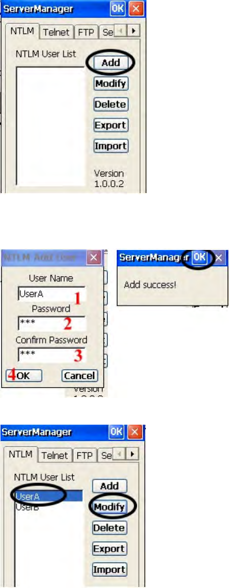
14
3. Key in the user name and password. Tap OK. Add Success. Tap OK.
4. To modify a user’s password, select the user and tap “Modify”.
5. Enter the new password and confirm password. Tap OK. Change password success.
Tap OK.
15
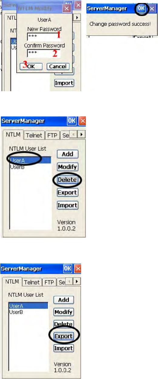
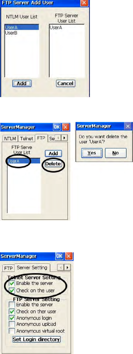
6. To delete a user, select the user you want to delete, tap “Delete”.
7. Tap “Export”. The user can backup SSID, WEP, all server users and this server’s
settings to \Flash Storage.
8. Tap “Import” to restore all settings.
16
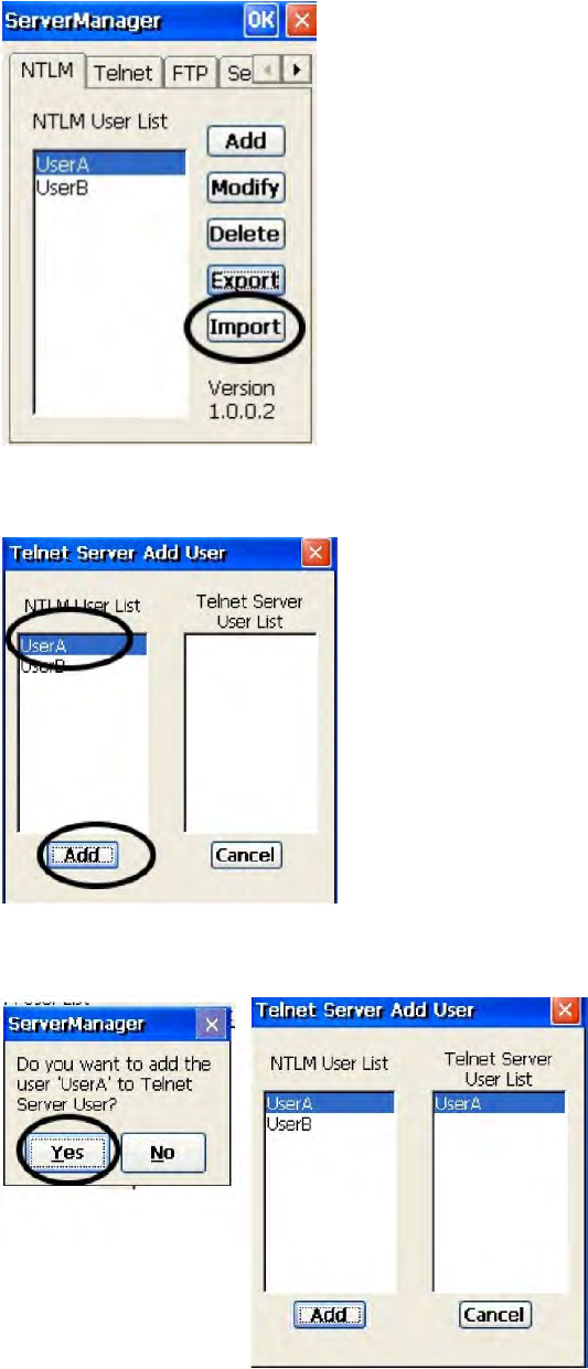
9. Under “Telnet” tab, tap “Add”. Add the telnet user from NTLM. Select the user and
tap “Add”.
10. Do you want to add user X to the telnet server? Tap “Yes”.
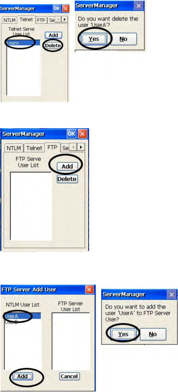
11. To delete telnet user, select the user and tap “Delete”. Do you want to delete the
user X? Tap “Yes”
17
12. Under “FTP” tab, tap “Add” to add ftp user.
13. Select the user and tap “Add”. Do you want to add user “X” to FTP server User?
Tap “Yes”.
18
14. To delete ftp user, select the user and tap “Delete”. Do you want to delete the user
X? Tap “Yes”.
15. Under “Server setting”tab, for telnet server setting, enable/disable server.
19
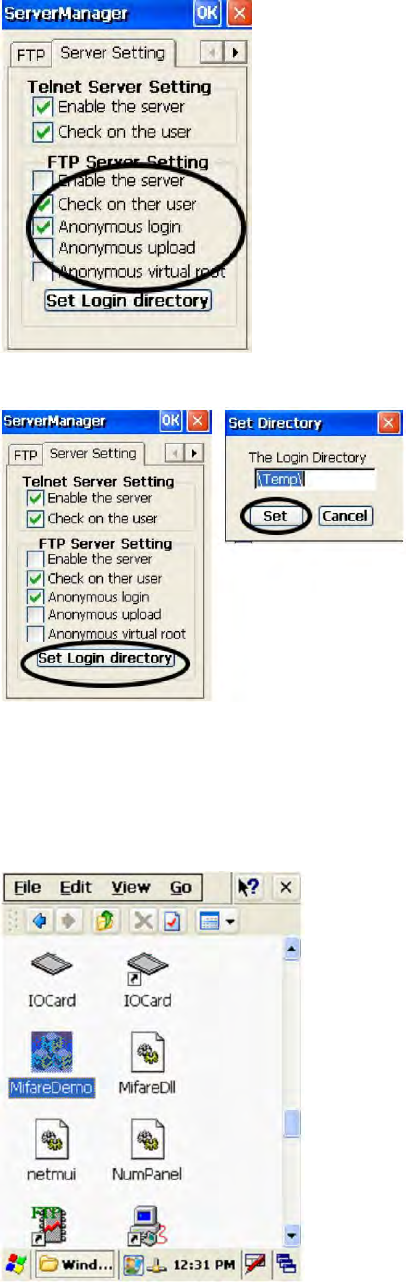
16. For FTP server setting, enable/disable server and define anonymous login.
17. Tap “Set Login Directory”. Define the login directory (Default is /Temp), tap “Set.
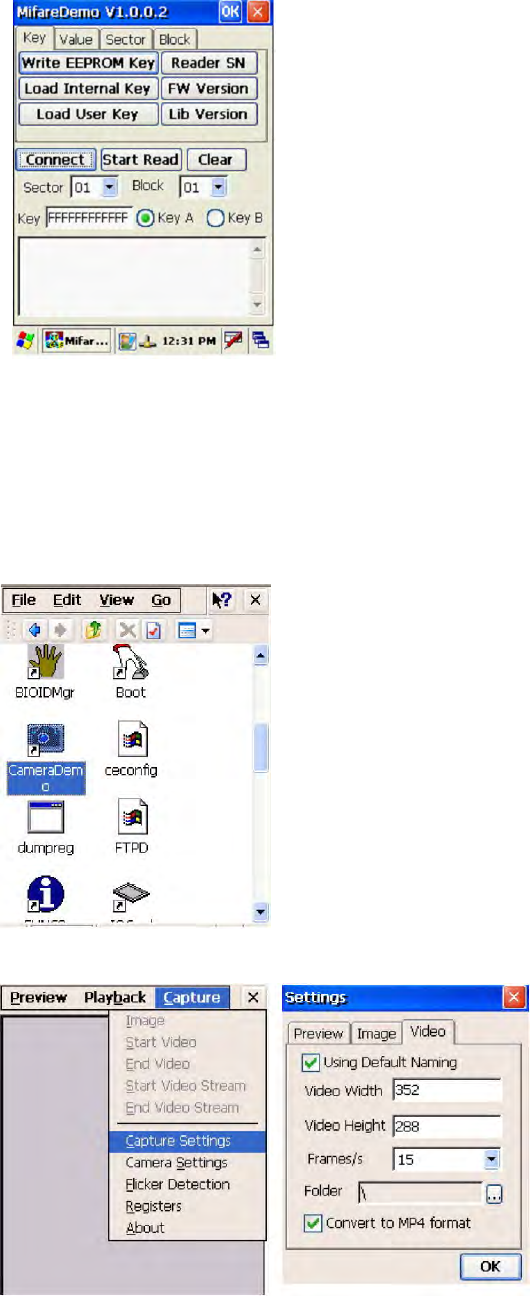
MifareDemo
This feature allows you to make Mifare card verification.
Path: /My Device/Windows/MifareDemo.exe
1. Double tap “MifareDemo”.
20
2. Under “Key”, select “Connect” to activate the program.
3. Tap “Start Read” and bring the Mifare card close to the sensor. The code will be
read and displayed on the following field.
4. Tap “Stop Read” to end reading.
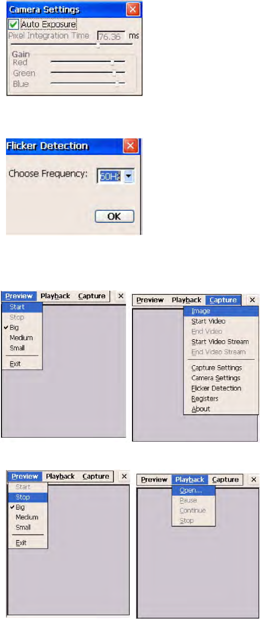
CameraDemo
This utility allows image capture and video streaming.
Path: /My Device/Windows/CameraDemo.exe
1. Double tap “CameraDemo”.
2. Under “Capture”, select “Capture Settings”. Define image and video dimension
and storage folder, then tap “OK”.
21
3. Under “Capture”, select “Camera Settings”. Define the pixel integration time.
4. Under “Capture”, select “Flicker Detection”. Select the frequency.
5. Under “Preview”, select “Start”. Your image will be focused. Under “Capture”,
select “image”.
6. Under “Preview”, select “Stop”. Under “Playback”, select “Open”. Select the
image file that was captured.
7. Tap “Preview/Exit” to close.
22
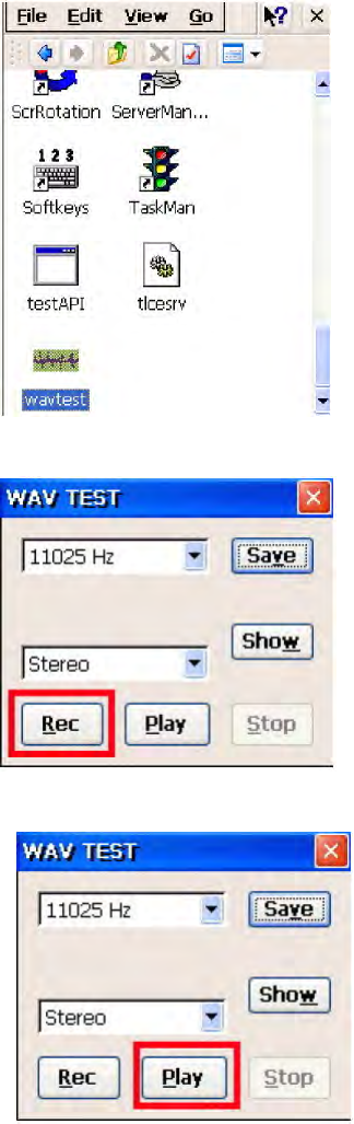
WavTest
Path: /My Device/WavTest
This tool is to test the audio recording and display.
1. Double tap “WavTest”.
2. Change to “Stereo”. Tap “Rec”. Talk near to the microphone port of MR650.
3. Tap “Stop” to stop recording. Tap “Play” to play the audio you just recorded.
4. Tap “Save” to save this audio as a wav file.
23
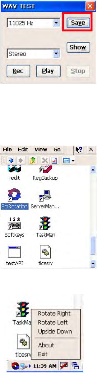
Screen Rotation
Path: /My Device/Windows/ScrRotation.exe
Screen Rotation allows the users to rotate the screen of terminal to the right, to the left
or upside down.
1. Double tap “ScrRotation.exe”.
2. The screen rotation icon will appear on the taskbar. Tap the icon to select the option
from the menu.
3. Tap “Rotate Right”. The screen is rotated to the right.
4. Tap “Rotate Left”. The screen is rotated to the left.
5. Tap “Upside Down”. The screen is flipped 180° vertically.
6. Tap “About”. The version of screen rotation is shown.
7. Tap “Exit”. Screen rotation icon is disappeared.
24
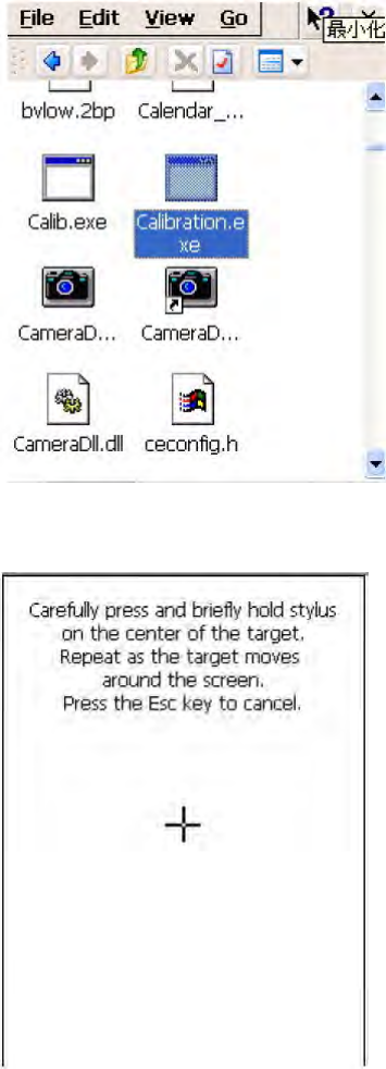
Calibration
This tool allows you to do calibration while the original screen calibration is no longer accurate.
Path:/My Device/Windows/Calibration.exe
1. Double tap “Calibration”.
2. Use the stylus to touch the “+” (Center, Top left, Bottom left, Bottom right, Top
right), then press “Enter” key.
25
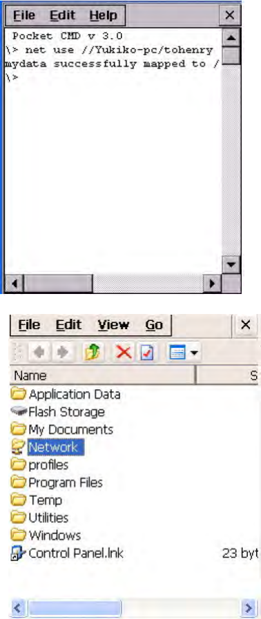
Net
Path: My Device/Windows/Net.exe
This is a MS Dos command that allows you to share data/files with any computer in the
network. (Your terminal must connect to network)
1. On your PC/notebook, share a folder to the network.
2. Execute MS DOS prompt command.
3. On the DOS prompt, type the command:
Net Use //<PC’s Name>/<Shared Folder Name> <Terminal folder’s name>
For Terminal folder’s name, you can specify any name you like.
4. In “My Device”, tap “Network”. You will see a terminal folder.
26
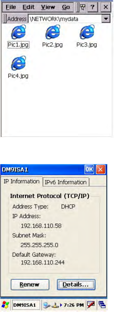
5. Open the folder. You will see the files in the folder. The content is the same as the
shared folder in your PC/notebook.
Windows CE Remote Management
1. Connect LAN cable to MR650.
2. Check IP address of MR650.
3. Input IP address of MR650 in the browser’s address bar.
4.Enter “admin” as default password and verify the password again.
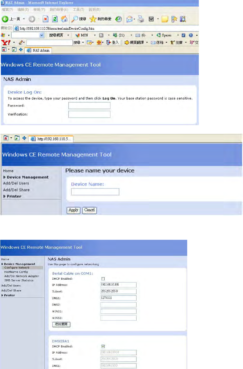
27
5.Please input Device Name you want and press “Apply”.
6. The Windows CE Remote Management Tool interface.
Device Management – Configure Network
28
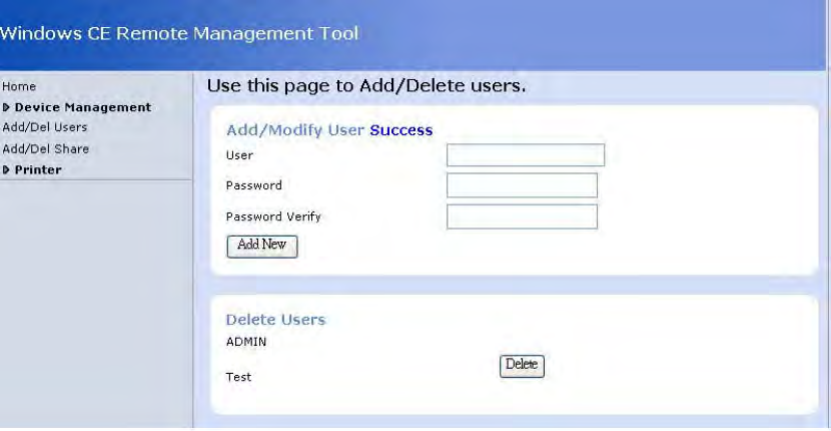
7. Click “Add/Del Users” to Add/Delete users.
You can add or delete any user, except Admin. After enter “Add New”, you can see your new
user under “Delete Users”
8. Click“Add/Del Network Adapter”. Select the adapter and click “Submit Query”.
9. Click “Add/Del Shares”, define a name for the folder of terminal that you want to
share.
10. Click “Permission”. Select “Allow” or “Deny” for the user’s access right. Click
“Update”. Click “Done”.
11. On the browser’s URL, enter \\<Device Name>\<folder name>. All the data of the
shared folder of the device are shown and they are ready to be shared.
12. To remove any shared folder, click “Remove”.
29
Data Communication
Chapter 3
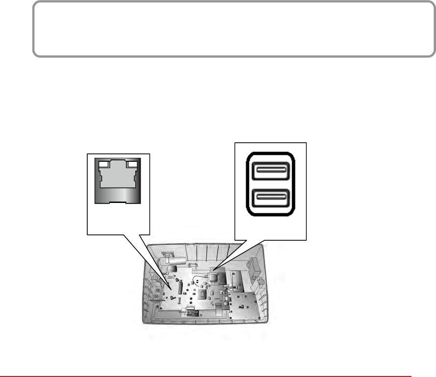
The MT700 can link to a host computer for data communication via USB or Ethernet cables.
USB and Ethernet port is on the front main board and is positioned as indicated in the diagram
below.
USB Port
Connect a USB cable to the MT700’s USB host port, and connect the other end to a USB
peripheral, such as a: Keyboard, mouse, memory card or HID compliant device.
USB
Ethernet
30
Power and Hardware
Chapter 4
The MT700 must work with external power. In this case, connect the MT700 to the AC outlet
with the power adapter.
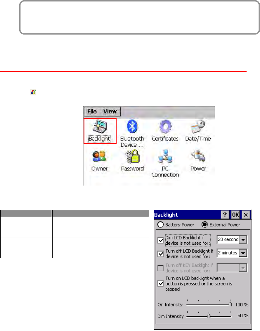
Adjusting the Backlight
Adjust the backlight screen settings through the following steps:
NOTE: The MT700 screen contrast has been preset by Unitech for optimum performance.
1. Tap Start → Settings → Control Panel → double-tap Backlight to adjust the screen
brightness.
2. The color display’s backlight can be customized for the Battery Power and External Power
conditions. Set the backlight behavior and drag the On Intensity and Dim Intensity sliders
to the desired levels.
Field
Description
Dim Backlight Minutes until the backlight dims.
Turn Off Backlight
Minutes until the backlight turns
automatically off.
Turn on Backlight The backlight turns on when a
button is pressed, or the
touch-screen is tapped.
31
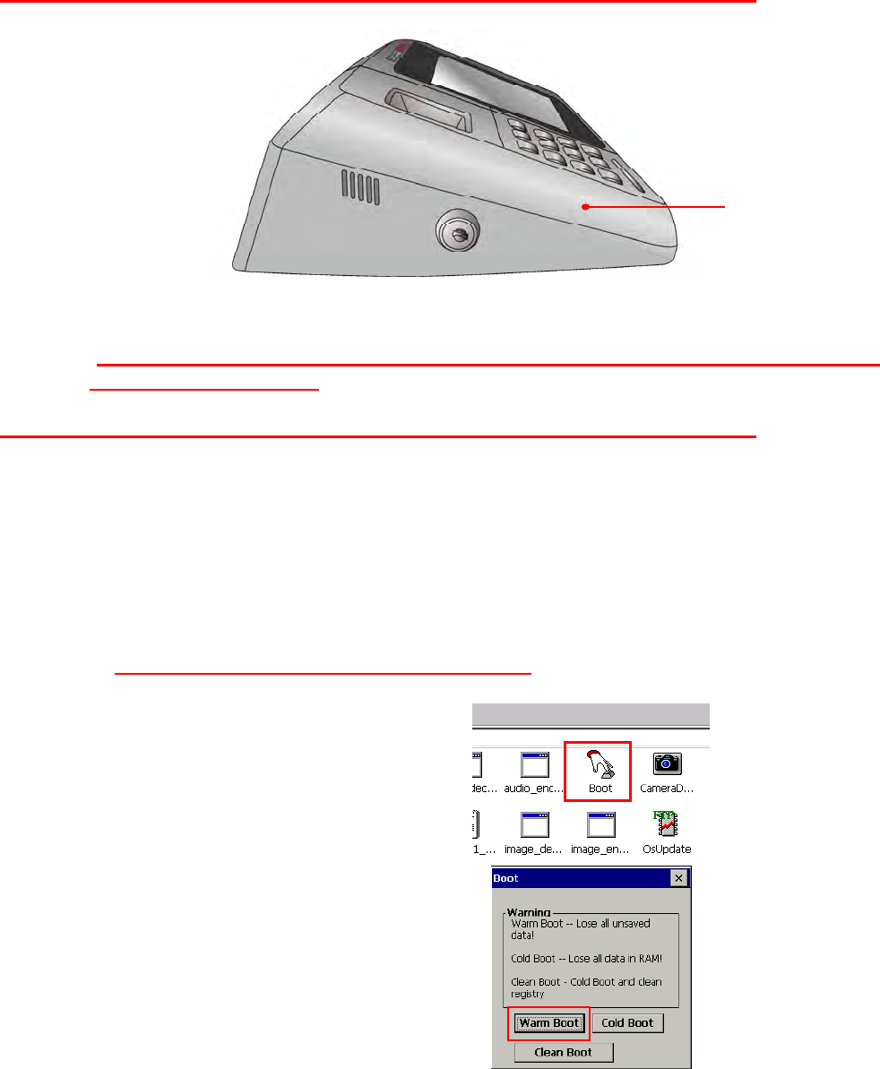
Hardware Reset
To perform a hardware reset, press the Hardware Reset button with a stylus or a sharp object.
Caution: If you perform the hardware reset, there is a possibility that the settings you
have done will be lost!
Performing a Software Reset
Perform a reset if the MT700 is frozen (i.e., the device no longer responds to pressing buttons
on/or the touch-screen).
Performing a Warm Boot
A Warm Boot is used to reset or reboot the device without losing data stored in RAM memory.
Perform a Warm Boot in any of the following situations:
The MT700 fails to respond.
After installing software applications.
After making changes to certain system settings (i.e. SD card).
CAUTION! A Warm Start will erase all unsaved data.
From Windows CE
1. Tap My Device → Windows → Boot.
2. Tap Warm Boot.
Reset
32
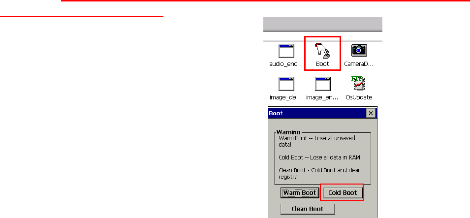
Performing a Cold Boot
A Cold Boot will erase all added data and programs, but it will restore the device to the default
factory settings. However, data and application programs stored in the Flash Storage will not
be deleted.
Always perform a Warm Boot before attempting to use a Cold Boot to correct a problem. Data
previously synchronized to the computer can be restored.
Perform a Cold Boot by using the BootMode utility in the operating system.
Perform a cold boot in the following situations:
Reset the operating system.
Restore the MT700 back to factory settings.
Reset the MT700 after a boot loader, keyboard and kernel upgrade.
CAUTION! A cold boot will erase all data and installed applications in RAM memory.
Method 1: From Windows CE
1. Tap My Device → Windows → Boot.
2. Tap Cold Boot.
Method 2: From Hardware
Pull out the power cable and then plug the cable into the DC input jack to cold boot
33
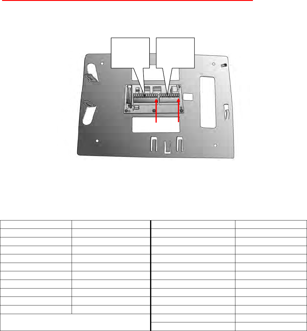
Terminal Block
The MT700 provides a 10-pin and a 12-pin terminal block plugs for input/output signals.
With reference to the illustrative figures below, Insert the terminal block plugs into the terminal
block sockets on the rear side of the MT700.
10 pin Terminal Block Pin
Assignment
12 pin Terminal Block Pin
Assignment
Pin Name Pin Name
Pin 1 12V Pin 1 RL1NO
Pin 2 GND Pin 2 RL1C
Pin 3 WIEGAND1_D0 Pin 3 RL1NC
Pin 4 WIEGAND1_D1 Pin 4 RL2NO
Pin 5 GND Pin 5 RL2C
Pin 6 5V Pin 6 RL2NC
Pin 7 WIEGAND2_D0 Pin 7 DI1-2
Pin 8 WIEGAND2_D1 Pin 8 DI1-1
Pin 9 GND Pin 9 DI2-2
Pin 10 5V Pin 10 DI2-1
Pin 11 RS485+ N/A
Pin 12 RS485-
Pin1
Pin1
12 pin
terminal
block
10 pin
terminal
block
34
System Specification
Appendix A
CPU TI OMAP DM3730 with DSP 1GHz Processor
Processor/Memory
Memory SDRAM: 512 MB
NAND Flash: 512 MB
OS Microsoft Windows CE 6.0 Professional Plus
Button 12 programmable numeric keys
Display 7 inches color (1024 x 600) Pixels
Backlight Touch-screen, TFT-LCD
Communication
1 X RJ45 with POE (DC12V/1A, IEEE802.3af Compliant)
RS485 Support (Optional RS485+, RS485-) baud rate at 15200 bps
or lower
USB v2.0 Host
Multimedia Audio: Two 1 Watt speakers
Microphone audio input
Programming SDK ModBus SDK supporting
Elfin utility
Power Source External Power (DC12V/2A)
Weight 1618 g.
Enclosure Dimension 297.53mm (L) X 203.98mm (W) X 74.98mm(H)
Operating temperature -10oC ~ 50oC
Storage temperature -20oC ~ 60oC
Environmental
Relative Humidity 10% – 95%
Certification CE, FCC, NCC, CB, BSMI and RoHS compliant
Programming VoIP/V2oIP, Video Streaming
RFID Reader (Optional)
EM+HID
MiFare 13.56MHz (ISO 14443A / ISO 14443-4B / ISO 15693 / NFC)
Finger print 1:N performance module
Camera 1.3 megapixel CMOS camera
Storage Micro SD slot and support up to 4Gb
35
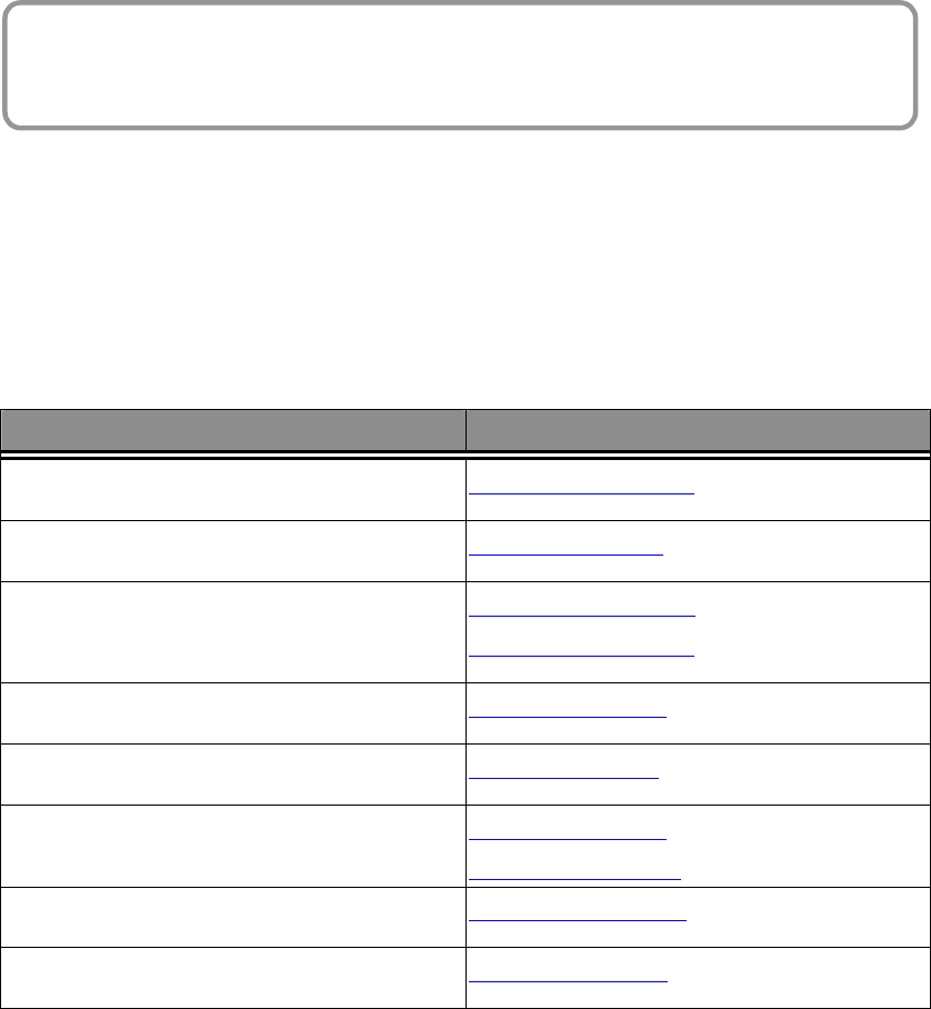
Worldwide Support
Appendix B
At unitech, we have a professional support team to answer your questions or
any related technical issues. If the equipment problem occurs, you may
contact our regional services representatives to get the quick response. We
have six regional services centers, and choose your region to get our quick
support and their contact information can be found in our websites provided
as below.
Region Web Site
Global Operation Center http://www.ute.com
Unitech Taiwan http://tw.ute.com
Unitech Asia Pacific & Middle http://apac.ute.com
http://india.ute.com
Unitech China http://cn.ute.com
Unitech Japan http://jp.ute.com
Unitech America http://us.ute.com
http://can.ute.com
Unitech Latin America http://latin.ute.com
Unitech Europe http://eu.ute.com