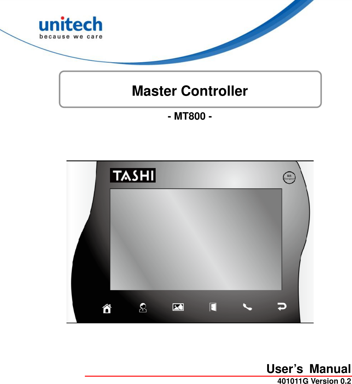
Unitech Electronics MT800BTNF Master Controller User Manual
Unitech Electronics Co., Ltd. Master Controller Users Manual
UserManual.wiki
>
Unitech Electronics
>
MT800BTNF User Manual
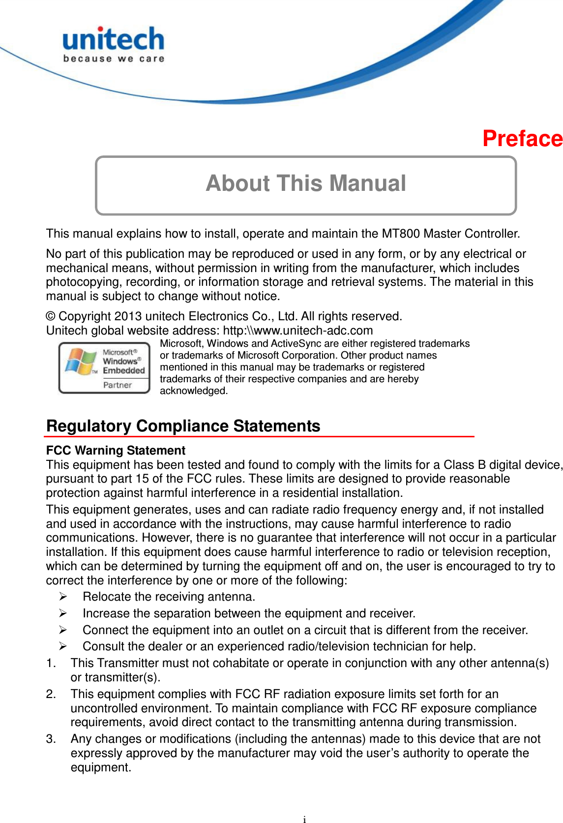
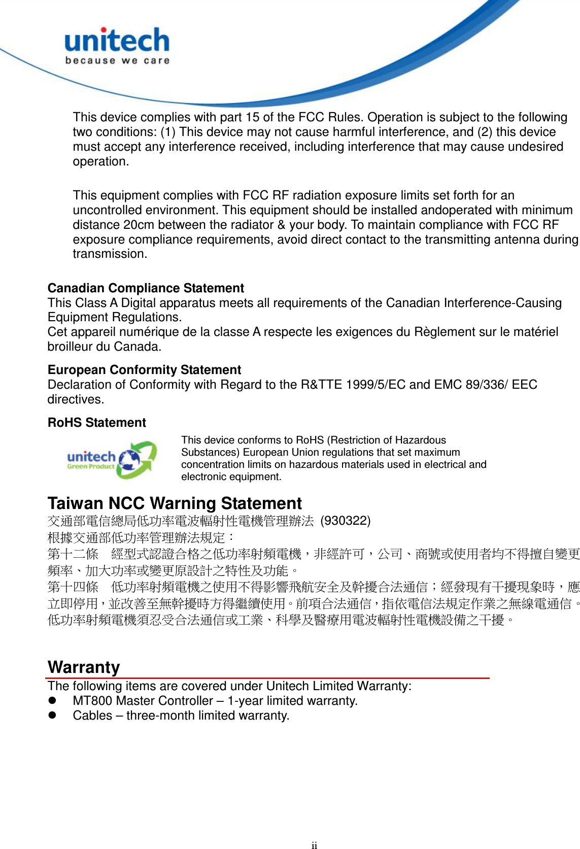
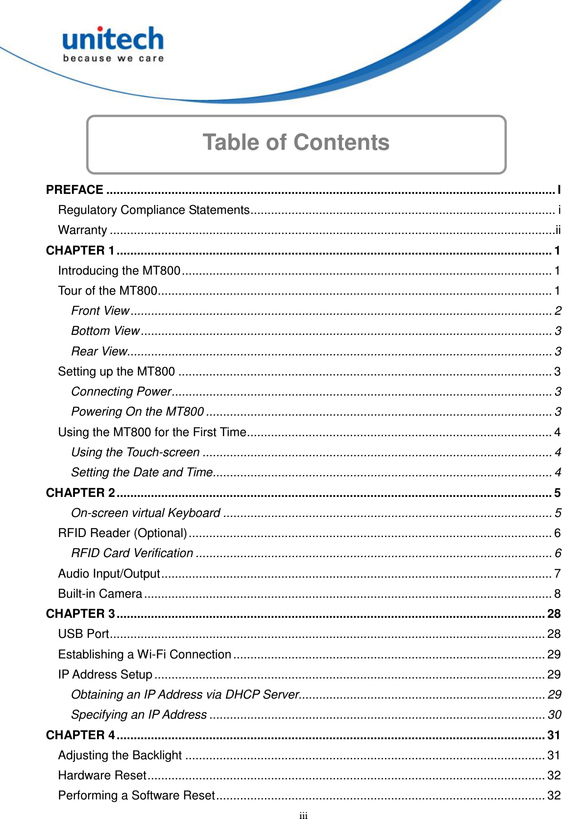
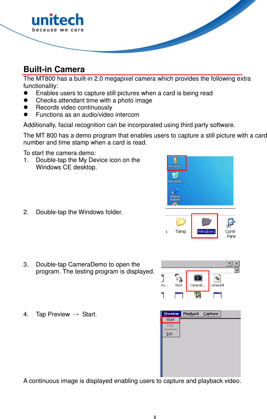
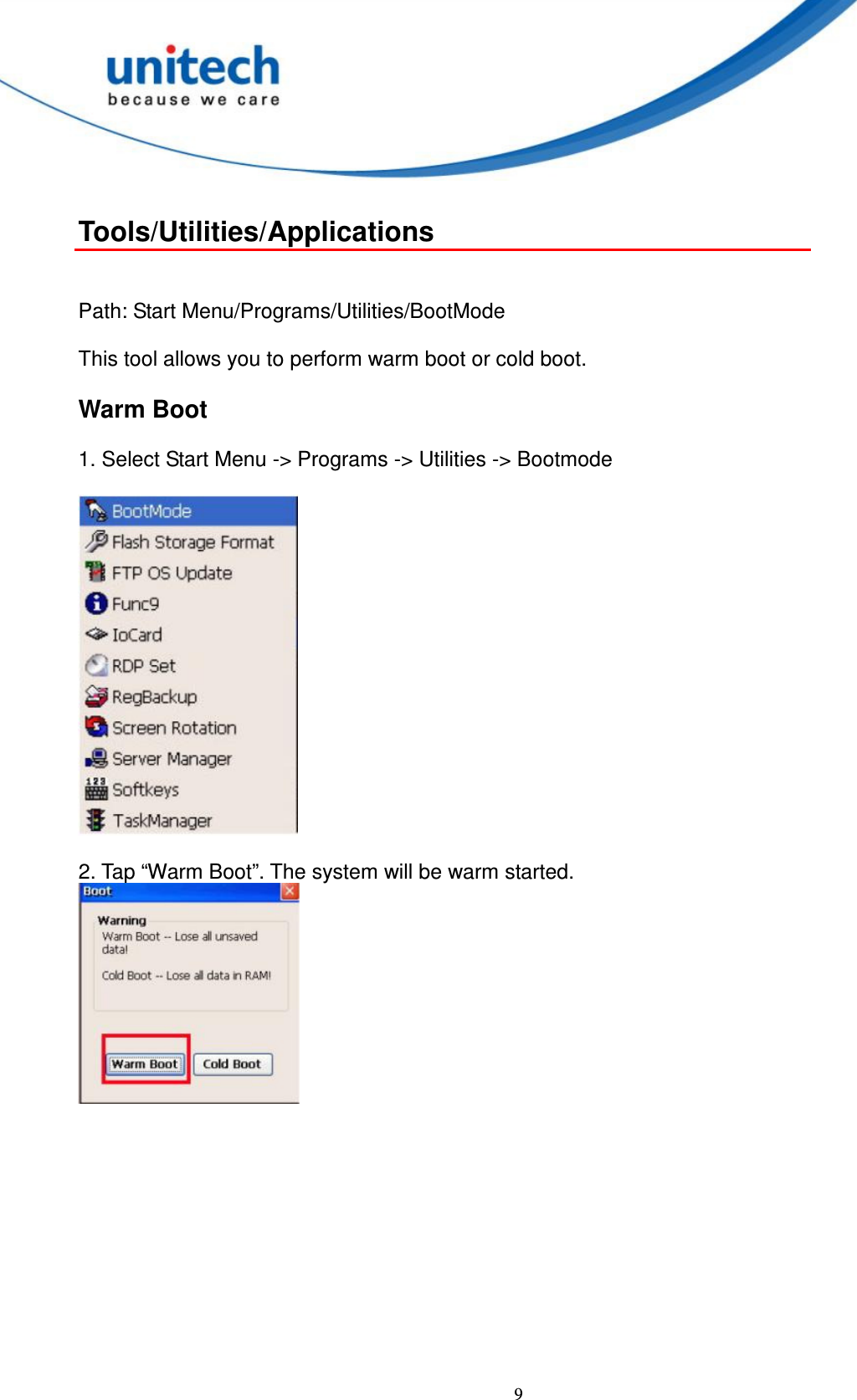
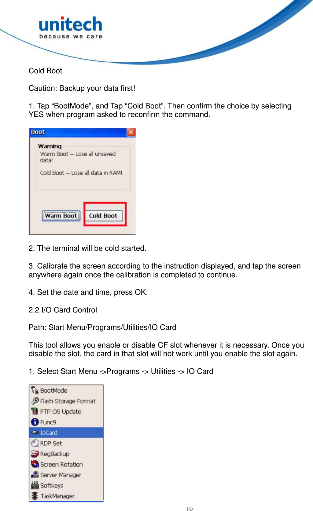
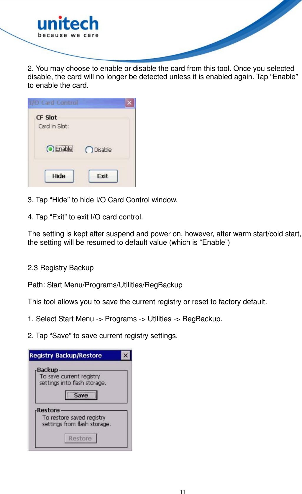
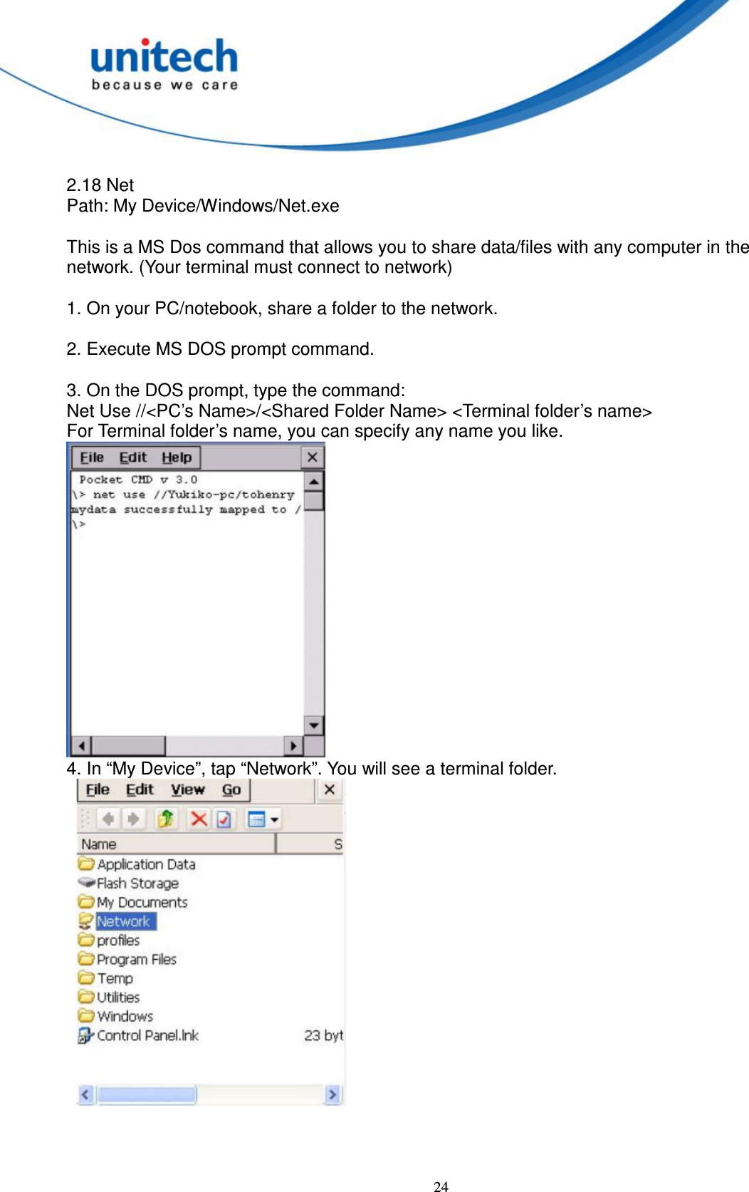
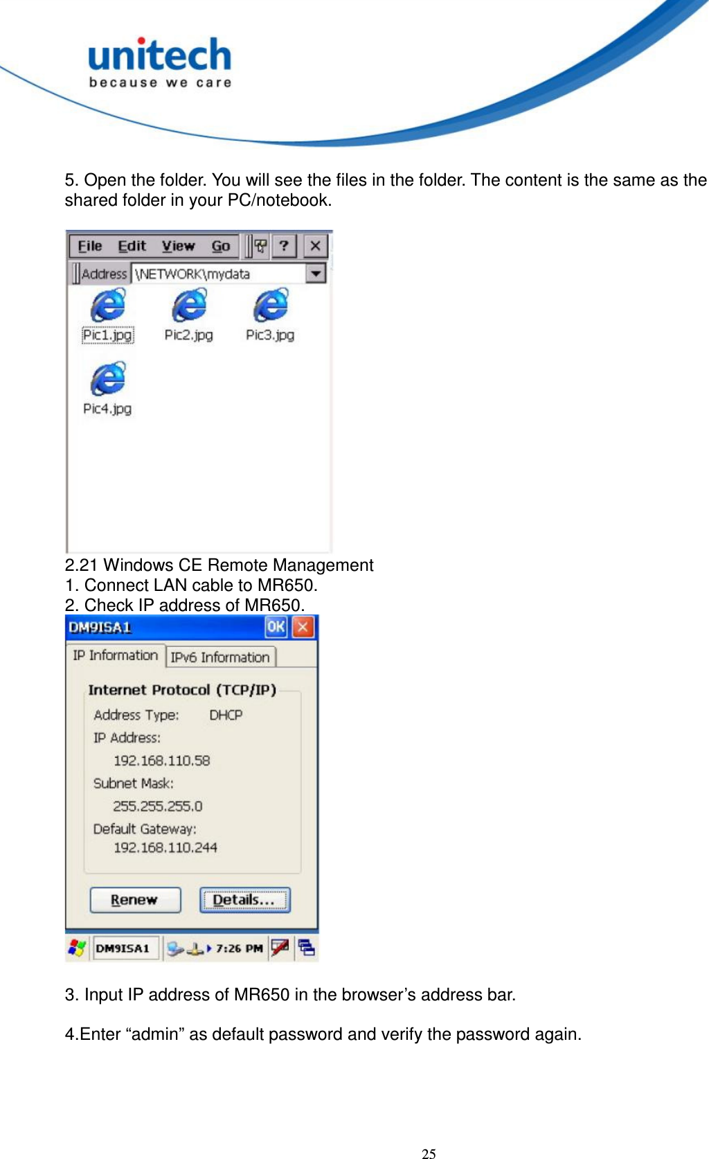
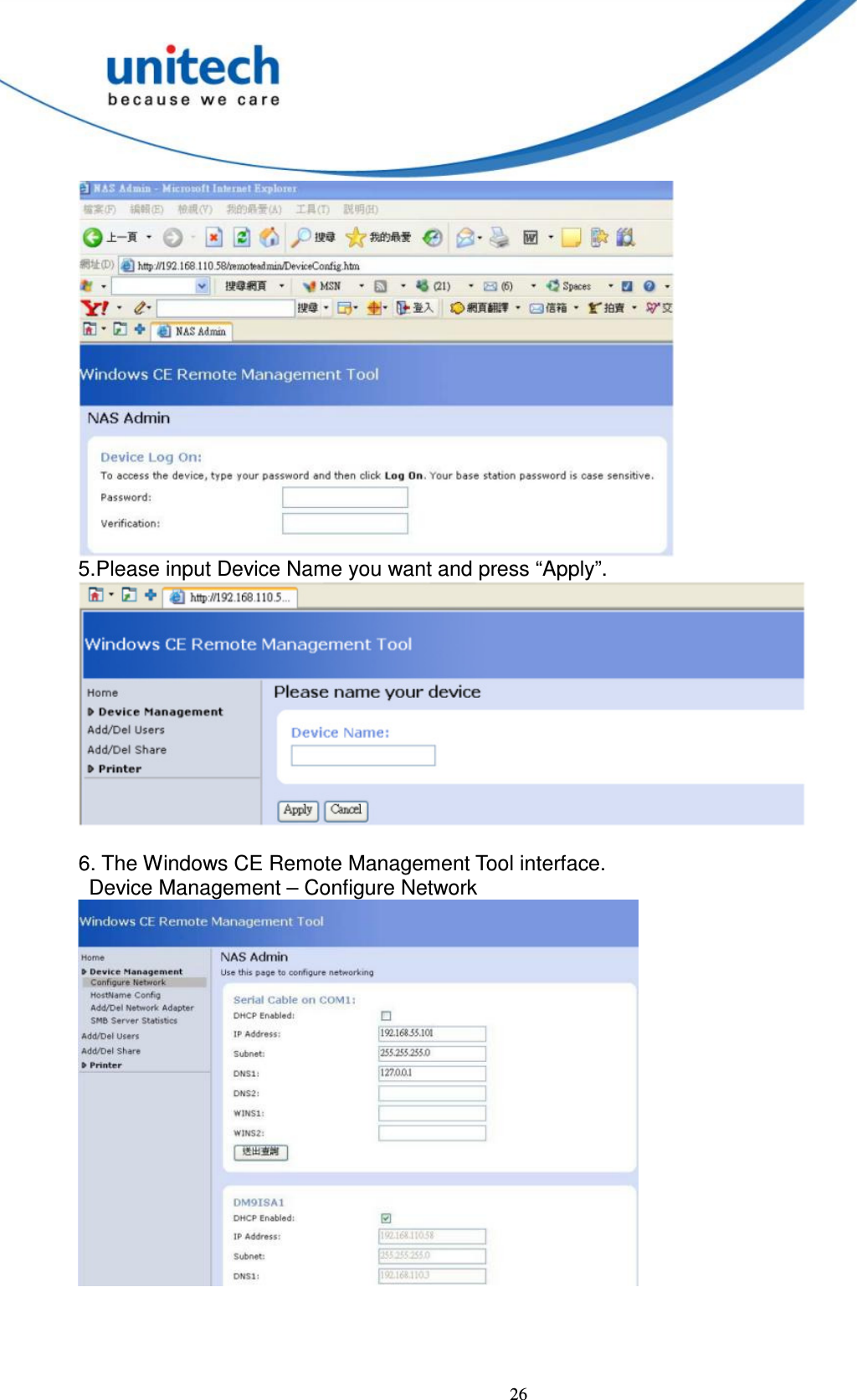
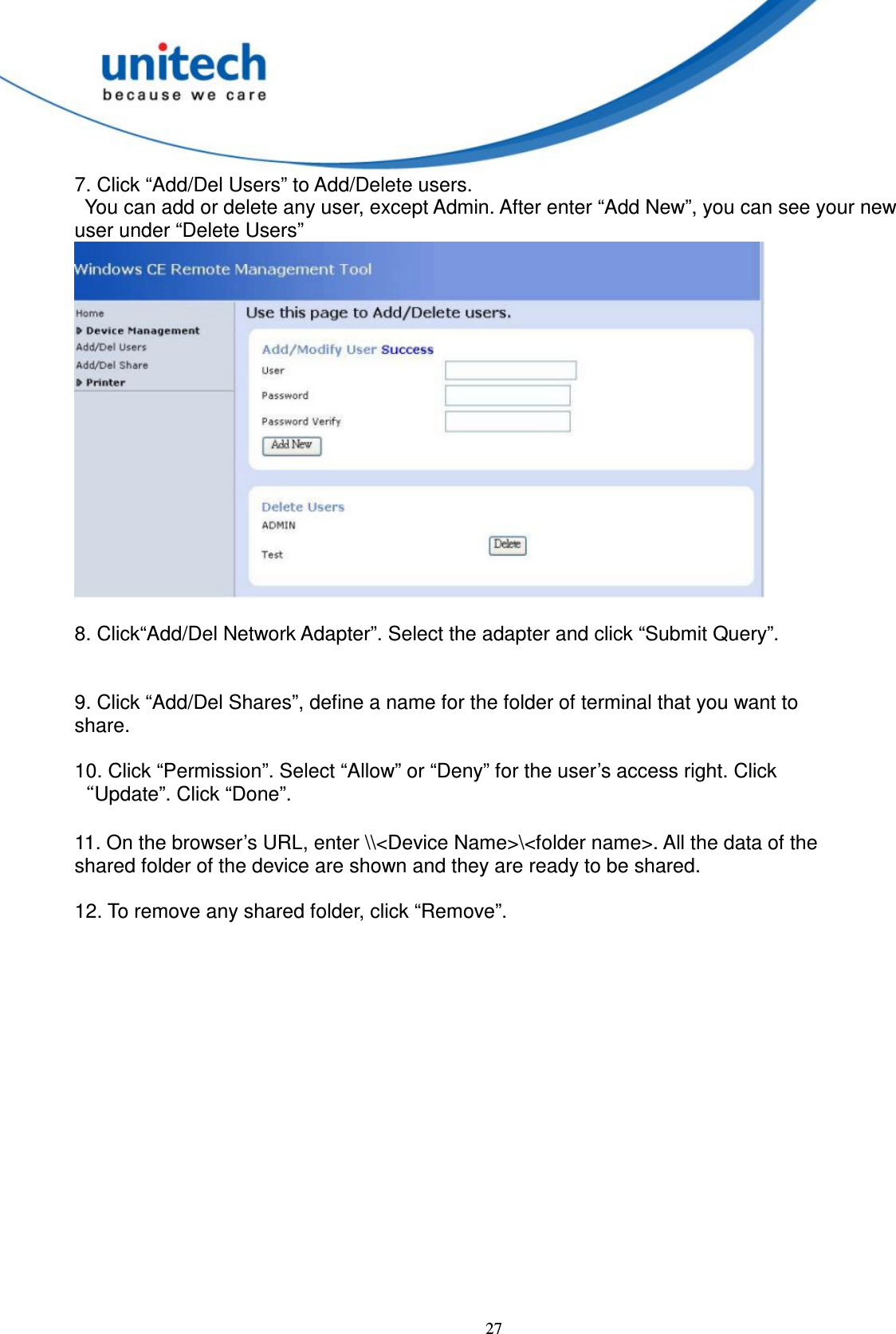
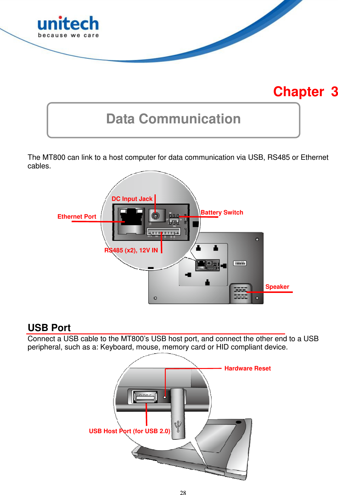
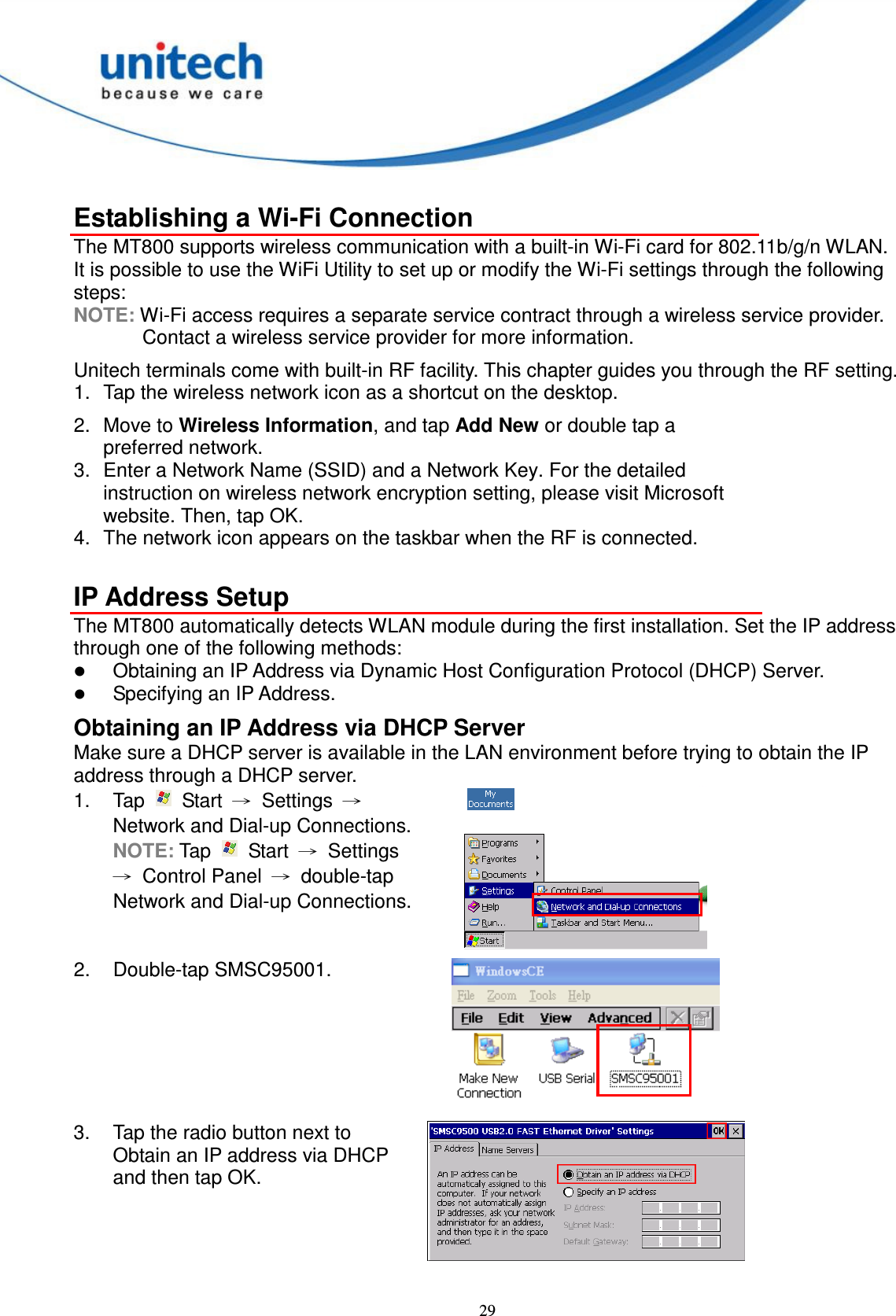
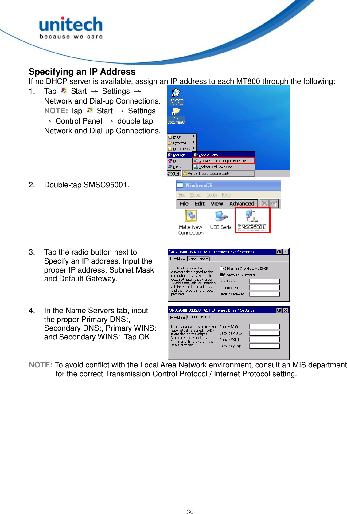
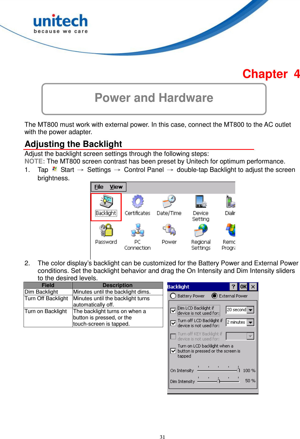
Users Manual
Navigation menu
Upload a User Manual
Namespaces
Wiki Guide
HTML
PDF
Info
Views
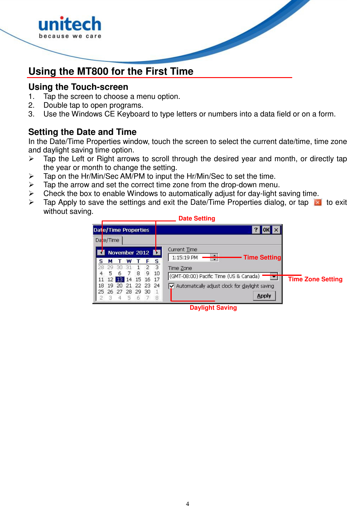
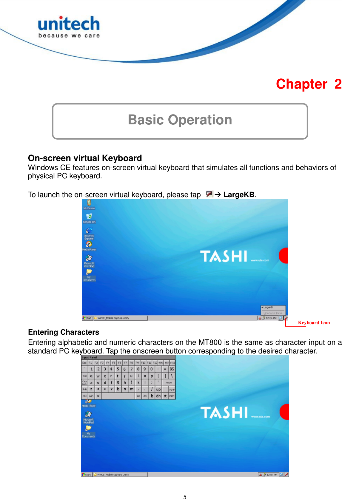
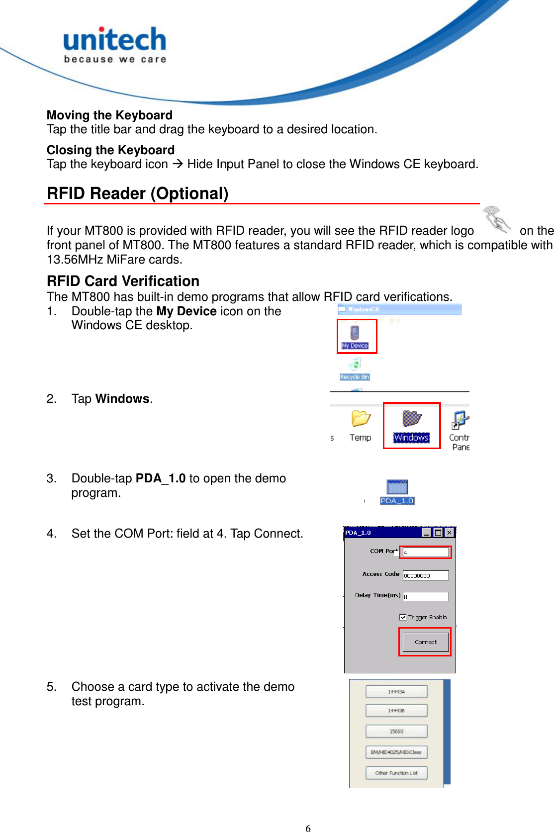
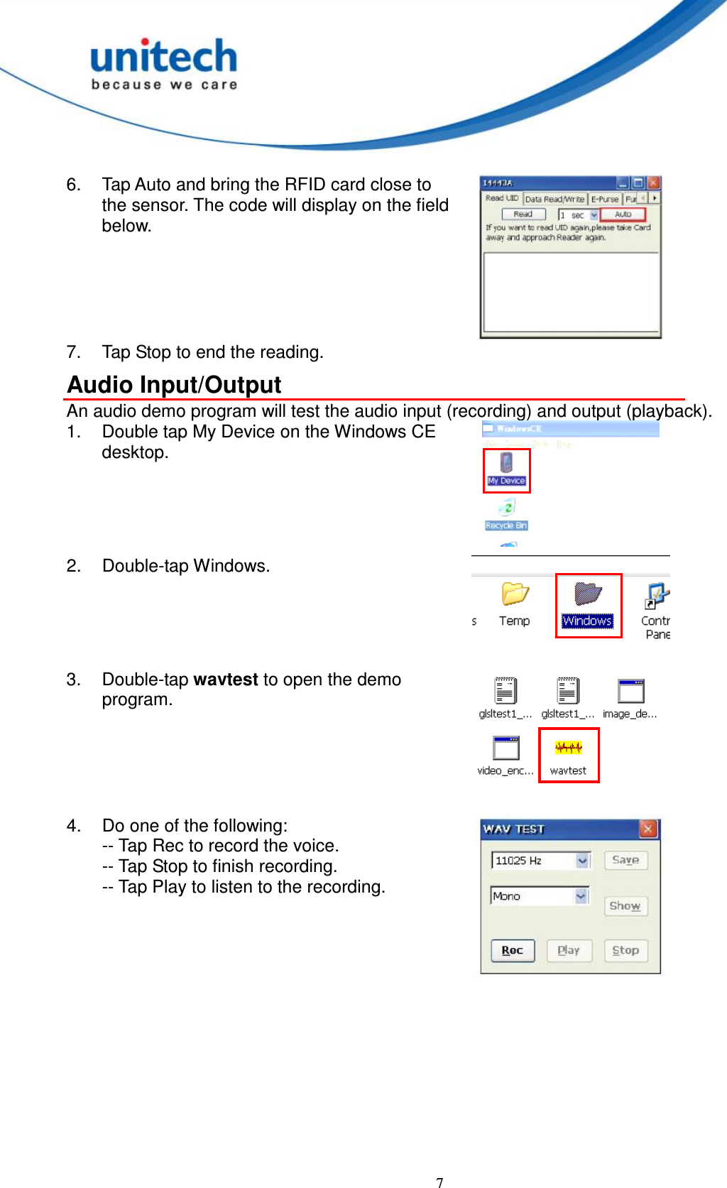
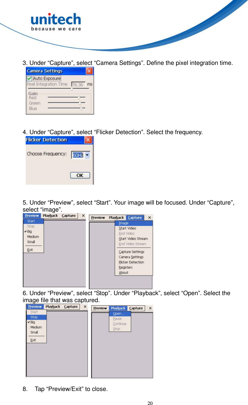
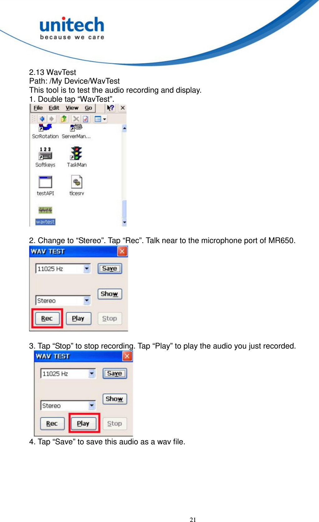
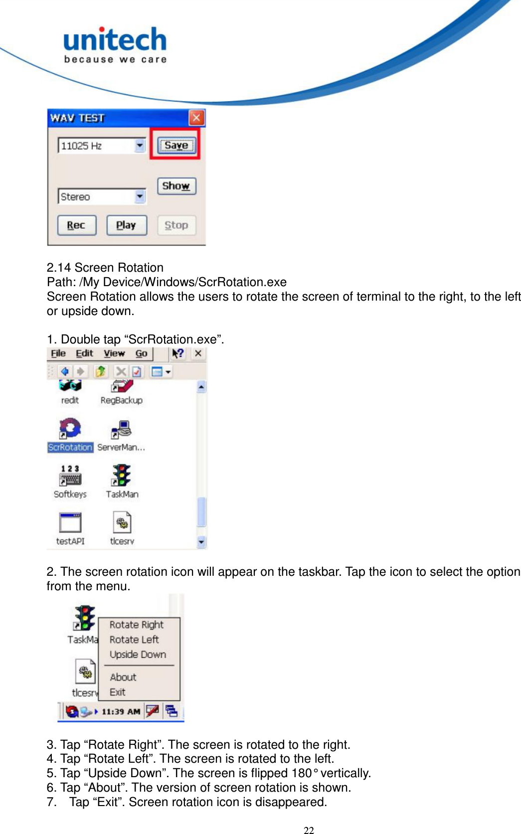
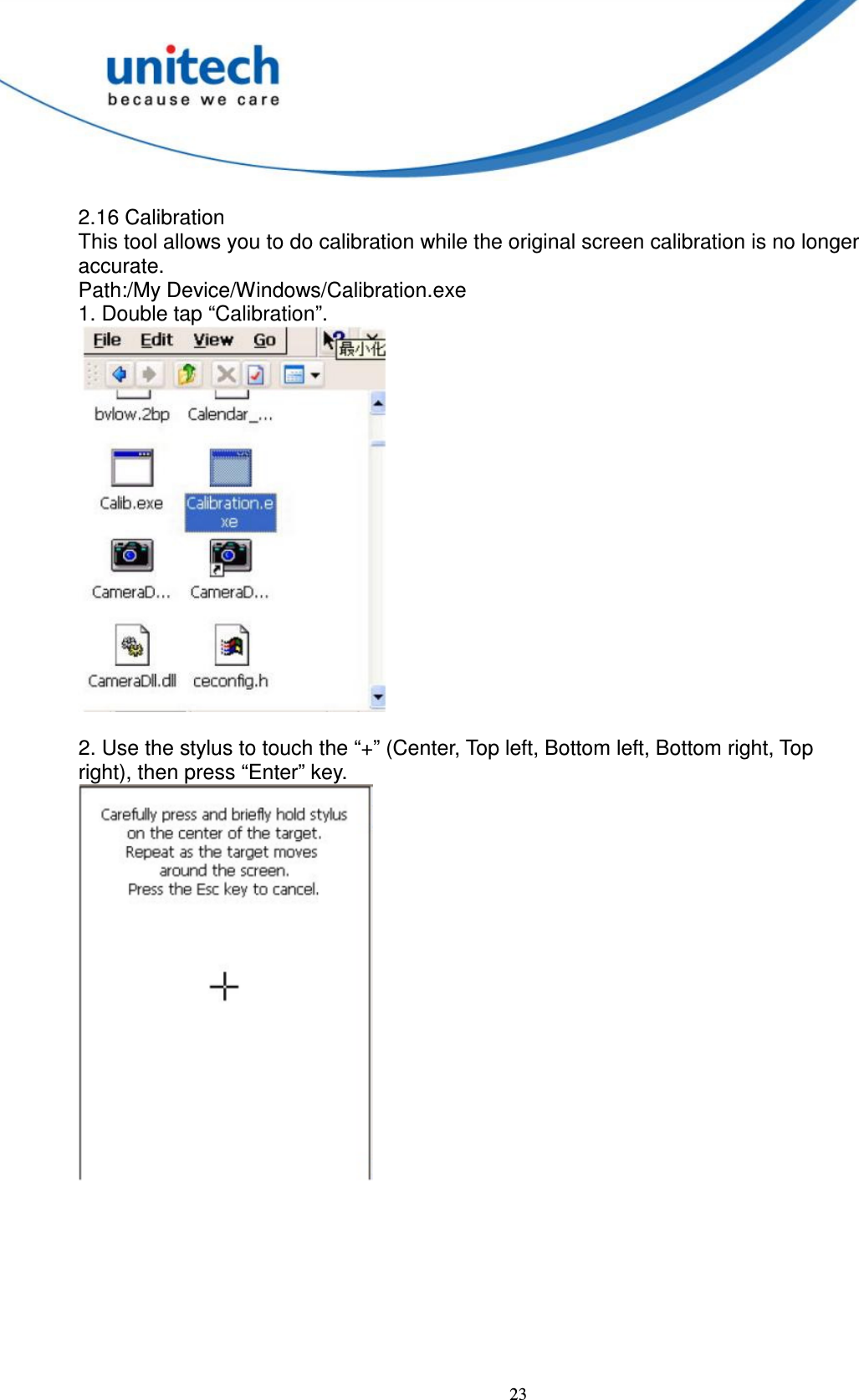
User Manual
Discussion / Help
Navigation