United Bus Tech WIFUN1050 Vehicle Wi-Fi Media Server User Manual UBT
United Bus Tech, Inc. Vehicle Wi-Fi Media Server UBT
User Manual

WIFUN1050VehicleWi‐FiMediaServer
User’sManual
©2015UBTInc.Allrightsreserved.
Republicationwithoutpermissionisprohibited.

WIFUN1050User’sManual
CopyrightNotice
Copyright©2015UBTInc.
Allrightsreserved.
Reproductionwithoutpermissionisprohibited.
Trademarks
UBTisaregisteredtrademarkofUnitedBusTech.Otherregisteredmarkscitedinthismanual
representedtheirrespectivecompanies.
Disclaimer
Informationinthisdocumentissubjecttochangewithoutnoticeanddoesnotrepresentan
obligationonthepartofUnitedBusTech.
Thisusermanualmayincludeintentionaltechnicalortypographicalerrors.Changesare
periodicallymadetothemanualtocorrectsucherrors,andthesechangesarenotinformedin
neweditions.
TechnicalSupportContactInformation
UnitedBusTechnology
info@ubt.io
TableofContents
WIFUN1050USER’SMANUAL...................................................................................................2
1.WIFUN1050INTRODUCTION..........................................................................................................6
1.1Overview.............................................................................................................................6
1.2Features...............................................................................................................................6
2.ESTABLISHNETWORKCONNECTION...................................................................................................9
2.1EstablishNetworkConnection............................................................................................9
2.1.1AutomaticacquisitionofIPaddress(recommended)..................................................9
2.1.2SetastaticIPaddress.................................................................................................12
2.2ConfirmthatthenetworkbetweenthesupervisoryPCandrouterisconnected............13
2.3CanceltheProxyServer....................................................................................................15
3.WEBCONFIGURATION..................................................................................................................17
3.1LogintheWebSettingPageofRouter..............................................................................17
3.2Management.....................................................................................................................18
3.2.1System........................................................................................................................18
3.2.1.1SystemStatus......................................................................................................18
3.2.1.2BasicSettings.......................................................................................................19
3.2.2SystemTime...............................................................................................................19
3.2.2.1SystemTime........................................................................................................20
3.2.2.2SNTPClientPort..................................................................................................20
3.2.3AdminAccess.............................................................................................................
22
3.2.3.1Createauser.......................................................................................................22
3.2.3.2ModifyaUser......................................................................................................23
3.2.3.3RemoveUsers......................................................................................................23
3.2.3.4ManagementService..........................................................................................24
3.2.4AAA.............................................................................................................................26
3.2.4.1Radius..................................................................................................................27
3.2.4.2Tacacs+................................................................................................................28
3.2.4.3LDAP....................................................................................................................29
3.2.4.4AAASettings........................................................................................................30
3.2.5ConfigurationManagement.......................................................................................32
3.2.6SNMP..........................................................................................................................33
3.2.6.1SNMP...................................................................................................................35
3.2.6.2SnmpTrap............................................................................................................37
3.2.7Alarm..........................................................................................................................37
3.2.7.1AlarmStatus........................................................................................................38
3.2.7.2AlarmInput.........................................................................................................39
3.2.7.3AlarmOutput......................................................................................................39
3.2.7.4AlarmMap...........................................................................................................41
3.2.8SystemLog.................................................................................................................41
3.2.8.1SystemLog..........................................................................................................41
3.2.8.2SystemLogSettings.............................................................................................42
3.2.8.3KiwiSyslogDaemon............................................................................................43
3.2.9SystemUpgrading.......................................................................................................43
3.2.10Reboot......................................................................................................................44
3.2.11CloudPlatform.........................................................................................................44
3.2.11.1CloudPlatform..................................................................................................44
3.2.11.2MOTTClient......................................................................................................45
3.2.12ScheduledTasks........................................................................................................46
3.3Network.............................................................................................................................46
3.3.1Cellular.......................................................................................................................46
3.3.1.1Status...................................................................................................................47
3.3.1.2Cellular................................................................................................................47
3.3.2WLANInterface(2.4G)...........................................................................................50
3.3.2.1Status...................................................................................................................50
3.3.2.2WLAN(2.4G).......................................................................................................50
3.3.2.3IPSetup...............................................................................................................53
3.3.2.4SSIDScan.............................................................................................................53
3.3.3WLANInterface(5.8G)...........................................................................................53
3.3.3.1Status...................................................................................................................53
3.3.3.2WLAN(5.8G)...................................................................................................54
3.3.3.3IPSetup...............................................................................................................56
3.3.3.4SSIDScan.............................................................................................................57
3.3.4CaptivePortal.............................................................................................................57
3.3.5DHCPservice..............................................................................................................59
3.3.5.1Status...................................................................................................................60
3.3.5.2DHCPServer........................................................................................................60
3.3.5.3DHCPRelay..........................................................................................................62
3.3.5.4DHCPClient.........................................................................................................62
3.3.6DNSServices...............................................................................................................63
3.3.6.1DNSServer..........................................................................................................64
3.3.6.2DNSRelay............................................................................................................64
3.3.7SMS............................................................................................................................65
3.3.8VLANInterface...........................................................................................................66
3.3.8.1VLANConfiguration.............................................................................................66
3.3.8.2VLANAggregation...............................................................................................67
3.3.9ADSLDialup(PPPoE)..............................................................................................68
3.3.10LoopbackInterface...................................................................................................69
3.3.11DynamicDomainName...........................................................................................71
3.3.12BridgeInterface........................................................................................................72
3.4LinkBackup.......................................................................................................................73
3.4.1SLA..............................................................................................................................73
3.4.2TrackModule..............................................................................................................74
3.4.3VRRP...........................................................................................................................76
3.4.4InterfaceBackup.........................................................................................................79
3.5Routing..............................................................................................................................80
3.5.1StaticRoute................................................................................................................80
3.5.1.1RoutingStatus.....................................................................................................81
3.5.1.2StaticRouting......................................................................................................81
3.5.2DynamicRouting........................................................................................................82
3.5.2.1RoutingStatus.....................................................................................................83
3.5.2.2RIP.......................................................................................................................83
3.5.2.3OSPF....................................................................................................................87
3.5.2.4FilteringRoute.....................................................................................................89
3.5.3MulticastRouting.......................................................................................................90
3.5.3.1BasicSettings.......................................................................................................90
3.5.3.2IGMP....................................................................................................................91
3.6Tools..................................................................................................................................
93
3.6.1PING...........................................................................................................................93
3.6.2RoutingDetection......................................................................................................94
3.6.3LinkSpeedTest...........................................................................................................94
3.7InstallationGuide..............................................................................................................95
3.7.1NewDial.....................................................................................................................95
3.7.2NewIPSecTunnel.......................................................................................................96
3.8PersonalizationFeatures...................................................................................................97
3.8.1NginxServer...............................................................................................................97
3.8.2FileSynchronization...................................................................................................98
3.8.3GPSLocationInformation..........................................................................................99
3.8.4RoamingManagement.............................................................................................100
3.8.4.1RoamingManagement......................................................................................100
3.8.4.2UpgradefromAP...............................................................................................100
3.9Firewall............................................................................................................................101
3.9.1AccessControl(ACL)............................................................................................101
3.9.2NAT...........................................................................................................................103
3.10QoS................................................................................................................................106
3.11VPN................................................................................................................................108
3.11.1IPSec.......................................................................................................................108
3.11.1.1IPSecPhase1...................................................................................................109
3.11.1.2IPSecPhase2...................................................................................................112
3.11.1.3IPSecConfiguration.........................................................................................113
3.11.1.4IPSecVPNConfigurationExample...................................................................114
3.11.2GRE.........................................................................................................................118
3.11.3L2TP........................................................................................................................120
3.11.4OPENVPN...............................................................................................................122
3.11.5CertificateManagement........................................................................................124
3.12ConfigurationWizard....................................................................................................126
4.APPLICATIONSCENARIOS.............................................................................................................128
APPENDIX1TROUBLESHOOTING..........................................................................................129
APPENDIX2INSTRUCTIONOFCOMMANDLINE....................................................................132
1.WIFUN1050Introduction
ThisChapterincludes:
Overview
Features
1.1Overview
WIFUN1050isadedicatedvehicleWi‐FiMediaServerwithembeddedNGINXwebserver
andlocalstorageSSD.WithWIFUN1050andtheRainbowWi‐Ficloud,motorcoachoperators
mayeasilysetupanadvancedWi‐Fioperatingsystemwhichprovidesdevicemanagement,
contentmanagement,vehiclelocationmanagement,visitormanagement,statisticalreports,and
otherfeatures.TravelerssimplyconnecttotheWi‐FihotspotprovidedbyWIFUN1050tosurf
Internet,andtoenjoylocalservicessuchasVODmoviesandinteractivegamesprovidedby
operators.BydeployingtheRainbowWi‐Ficloud,motorcoachoperatorsmayeasilyremotely
managethousandsofWIFUN1050devices,nomatterchangingvisitorpolicyorupdatingmedia
contentdeployedinWIFUN1050.
TheWIFUN1050isaportalintothemobileinternetandastepforwardinproviding
value‐addedservicestotravelers.
1.2Features
AdvancedWi‐Fi
Supportdualband2.4GHzand5.8GH,fullycompliancewithIEEE802.11ac/a/b/g/n
standards.
With2X2MIMOtechnologyenabled,Wi‐Ficonnectionbandwidthcanreachashighas
1.2Gbps,bringsamazingmulti‐userperformance.
High‐speed4GAccess
Integratinguptotwo4Gcellularmodules,WIFUN1050providesreliable
TD‐LTE/FDD‐LTEaccess,with100Mbpsuplinkand50Mbpsdownlink.
QuadBandLTE:700/850/AWS(1700/2100)/1900MHz;FDD‐Band(17,5,4,2);TriBand
UMTS(WCDMA):850/AWS(1700/2100)/1900MHz;FDD‐Band(5,4,2)QuadBand
GSM/GPRS/EDGE:850/900/1800/1900MHz
GPS
WithGPSenabled,WIFUN1050providesvehiclelocation,speed/courseoverground
andtrackinformation.
PowerfulWebPortal
WhenvisitorsconnecttotheWi‐FihotspotprovidedbyWIFUN1050,agreetingsplash
pagepopsup,providinglocalmediaservicesanduserauthentication.
Built‐inWebServer
EmbedreliableNGINXwebserver,enablinglocalmediaservices.
SupportPHP,enablingdynamicpagecontent.
LocalStorage
SupportSSDupto1TB,toleratingvibrationfromvehicle.
Localstoragemaybeusedtostorelocalwebcontent,movies,music,apps,etc.to
acceleratelocalaccessandtosaveinternetbandwidth.
ContentUpdateMechanism
Inremotesynchronizationmode,locallystoredcontentsmaysyncwiththecloud.
Inlocalsynchronizationmode,contentmaybeupdatedviaSDcardorFTP.
Bothmodesmaybehybridtoenableevenmoreflexibleoperation.
VisitorBehaviorManagement
SupportvisitorauthenticationbySMSorsocialaccounts.
SupportQoStolimitper‐userbandwidthandtraffic,preventingoveragesand
protectinglatency‐sensitivetraffic.
Supportwebsitesblacklistandwhitelist.
CloudManagement
SupporttheRainbowWi‐Ficloud,enablingdevicemanagement,contentmanagement,
vehiclelocationmanagement,visitormanagement,statisticalreports,andother
features.
SupportCLI,webUIandSNMPv3.
HighReliability
Withdedicatedvehiclepowermoduleinside,WIFUN1050toleratespowervoltagedips,
overruns,shortandotherfailures.SupportautomaticallypowercontrolwithACC
signaltoprotectSSDandvehiclebattery.
Fanlesscoolingdesigntosimplifyinstallation.
Supportlinkqualityinspectionandauto‐recoverytoensurereliableLTEaccess.
RobustSecurity
SupportIPSecVPN,DMVPN,L2TP,SSLVPN,andCAcertificationtoensuredata
security.
SupportpowerfulfirewallfunctionssuchasStatefulPacketInspection(SPI),Access
ControlList(ACLs),DoSattackprevention,etc.
SupportAAA,TACACS,Radius,localauthentication,andmultilevelsuserauthorityto
ensuresecuremanagement.
2.EstablishNetworkConnection
Thischaptermainlycontainsthefollowingcontents:
EstablishNetworkConnection
ConfirmthattheconnectionbetweensupervisoryPCandrouter
CanceltheProxyServer
Aftercompletingthehardwareinstallation,beforetologintheWebset‐uppage,youneedto
ensurethatthemanagementoftheEthernetcardinstalledonyourcomputer.
2.1EstablishNetworkConnection
2.1.1AutomaticacquisitionofIPaddress(recommended)
Pleasesetthesupervisorycomputerto"automaticacquisitionofIPaddress"and"automatic
acquisitionofDNSserveraddress"(defaultconfigurationofcomputersystem)tolettherouter
automaticallyassignIPaddressforsupervisorycomputer.
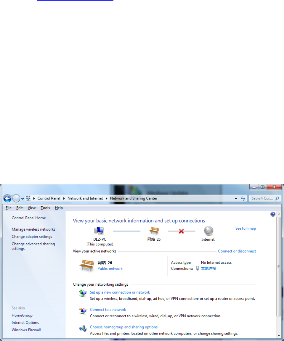
1)Open“ControlPanel”,doubleclick“NetworkandInternet”icon,enter“NetworkandSharing
Centers”
2)Clickthebutton<LocalConnection>toenterthewindowof"LocalConnectionStatus”
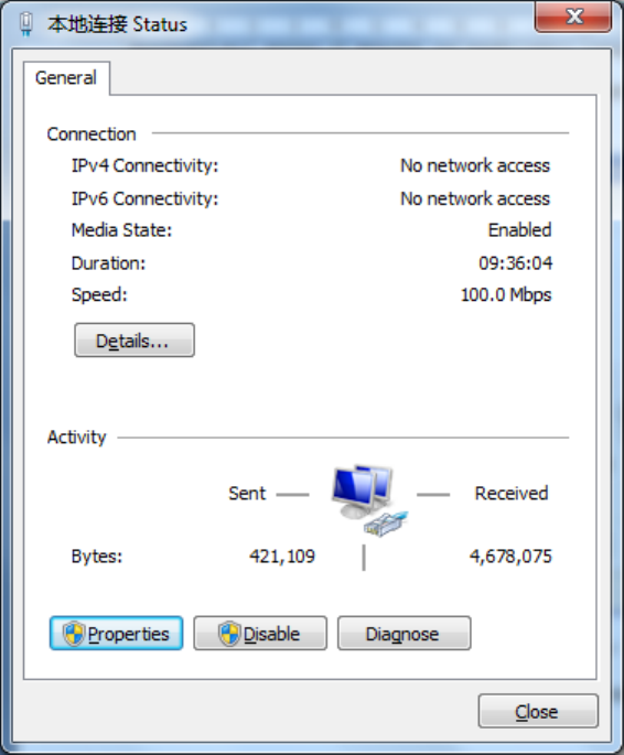
3)Click<Properties>toenterthewindowof"LocalConnectionProperties”,asshownbelow.
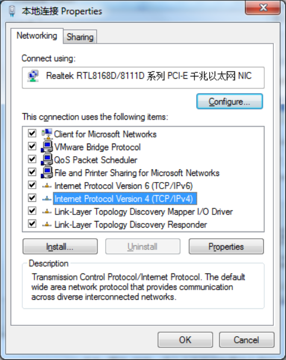
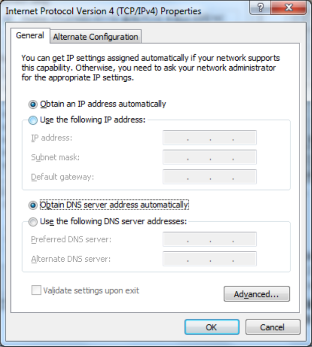
4)Select“InternetPortocolVersion4(TCP/IPv4)”,click<Properties>toenter“InternetPortocol
Version4(TCP/IPv4)Properties”page.Select“ObtainanIPaddressautomatically”and“Obtain
DNSServeraddressautomatically”,thenclick<OK>tofinishsetting,asshownbelow.
2.1.2SetastaticIPaddress
SetcomputermanagementIPaddressanddevieceFEportIPaddressonthesamenetwork
segment(deviceFEportinitialIPaddress:192.168.2.1,SubnetMask:255.255.255.0).The
followingFE1/1portconnectedtoacomputerandmanagementprovidedinWindowsXPsystem
describedasanexample.
Enter“InternetPortocol(TCP/IP)Properties”page,select“UsethefollowingIPaddress”,typeIP
address(arbitraryvaluebetween192.168.2.2~192.168.2.254),SubnetMask(255.255.255.0),
andDefafultGateway(192.168.2.1),thenclick<OK>tofinishsetting,asshownFigure2‐5.
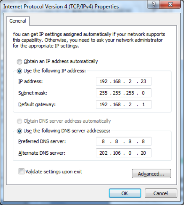
Figure2‐5InternetPortocol(TCP/IP)Properties
2.2ConfirmthatthenetworkbetweenthesupervisoryPCandrouterisconnected
1)Clickthelowerleftcornerofthescreen<Start>buttontoenterthe"Start"menu,select"Run"
pop‐up"Run"dialogbox,showninFigure2‐6.
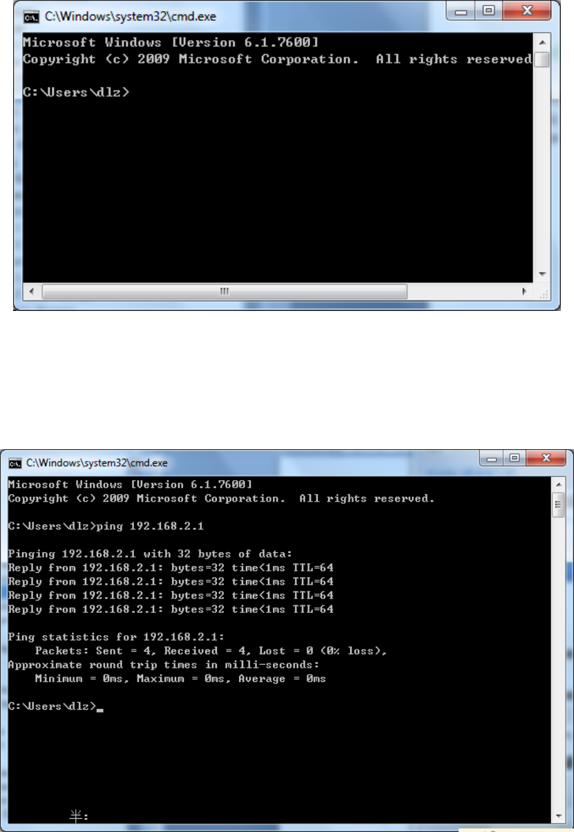
Figure2‐6Run
2)Enter"ping192.168.2.1(IPaddressofrouter;itisthedefaultIPaddress),andclickthebutton
<OK>.Ifthepop‐updialogboxshowstheresponsereturnedfromtherouterside,itindicates
thatthenetworkisconnected;otherwise,checkthenetworkconnection,showninFigure2‐7.
Figure2‐7CommandPrompt
2.3CanceltheProxyServer
IfthecurrentsupervisorycomputerusesaproxyservertoaccesstheInternet,itisrequiredto
canceltheproxyserviceandtheoperatingstepsareasfollows:
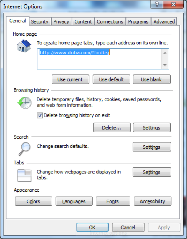
1)Select[Tools/InternetOPtions]inthebrowsertoenterthewindowof[InternetOptions],
showninFigure2‐8.
Figure2‐8InternetOPtions
2)Selectthetab”Connect”andclickthebutton<LANSetting(L)>toenterthepageof“LAN
Setting”.Pleaseconfirmiftheoption”UseaProxyServerforLAN”ischecked;ifitis
checked,pleasecancelandclickthebutton<OK>,showninFigure2‐9.
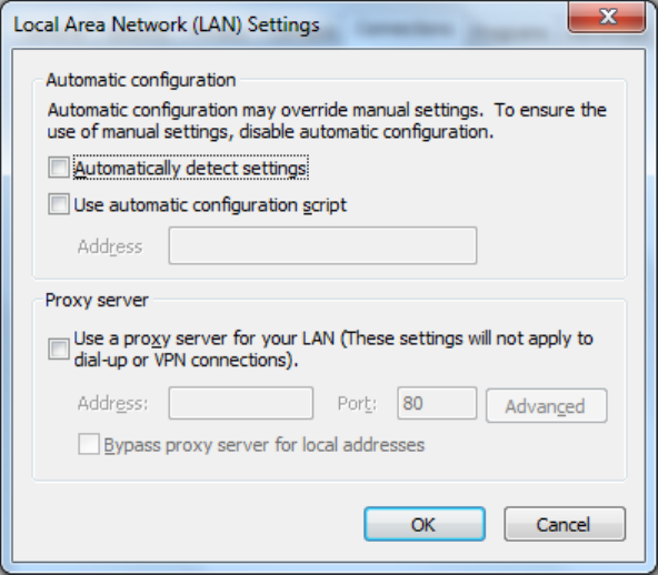
Figure2‐9LANSetting

3.WebConfiguration
Thischapterincludesthefollowingparts:
Login/outWebConfigurationPage
Management
Network
LinkBackup
Routing
Tools
InstallationGuide
PersonalizationFeatures
Firewall
Qos
VPN
3.1LogintheWebSettingPageofRouter
RuntheWebbrowser,enter“http://192.168.2.1:8080”intheaddressbar,andpressEntertoskip
totheWebloginpage,asshowninFigure3‐1.Enterthe“UserName”(default:adm)and
“Password”(default:123456),andclickbutton<OK>ordirectlypressEntertoentertheWeb
settingpage.

Figure3‐1LoginRouter
AfterenteringtheWebSettingpage,clickthe"AdvancedConfiguration"webinterface,the
pop‐updialogbox,enter"UserName"(default:adm)againand"Password"(default:123456),
thenentertheparameterconfigurationinterfacestartparametersettings.Advanced
configurationisshownin3.2~3.11.
Atthesametime,therouterallowsuptofouruserstomanagethroughtheWebsetting
page.Whenmulti‐usermanagementisimplementedfortherouter,itissuggestednotto
conductconfigurationoperationfortherouteratthesametime;otherwiseitmayleadto
inconsistentdataconfiguration.
Forsecurity,youaresuggestedtomodifythedefaultloginpasswordafterthefirstlogin
andsafekeepthepasswordinformation.
3.2Management
3.2.1System
3.2.1.1SystemStatus
Fromtheleftnavigationpanel,selectAdministration/System,thenenter“SystemStatus”page.
Onthispageyoucanchecksystemstatusandnetworkstatus,asshowninFigure3‐2.Insystem
status,byclicking<SyncTime>youcanmakethetimeofroutersynchronizedwiththesystem
timeofthehost.Clickthe“Set”onnetworkstatustoenterintotheconfigurationscreendirectly.
Forconfigurationmethods,refertoSection3.3.2.
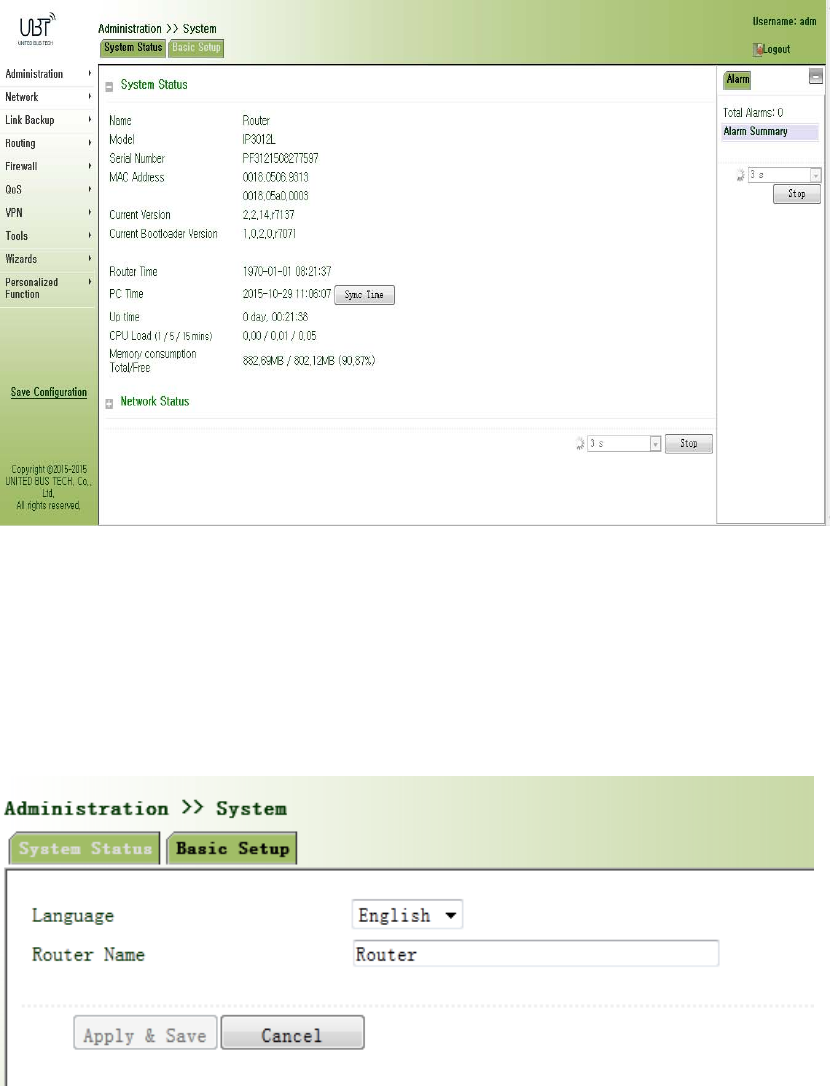
Figure3‐2SystemStatus
3.2.1.2BasicSettings
SelectAdministration/System,thenenter“BasicSetup”page.YoucansetthelanguageofWeb
ConfigurationPageanddefineRouterName,asshowninFigure3‐3.
Figure3‐3BasicSettings
3.2.2SystemTime
Toensurethecoordinationbetweenthisdeviceandotherdevices,userisrequiredtosetthe
systemtimeinanaccuratewaysincethisfunctionisusedtoconfigureandchecksystemtimeas
wellassystemtimezone.
Thedevicesupportsmanualsettingofsystemtimeandthetimetopassself‐synchronisticSNTP
server.
3.2.2.1SystemTime
Timesynchronizationofrouterwithconnectedhostcouldbesetupmanuallyinsystemtime
configurationpartwhilesystemtimeisallowedtobesetasanyexpectedvalueafterYear2000
manually.
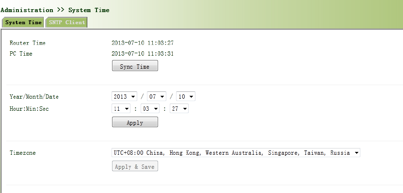
Fromtheleftnavigationpanel,selectAdministration/SystemTime,thenenter“SystemTime”
page,asshowninFigure3‐4.
Byclicking<SyncTime>youcanmakethetimeofroutersynchronizedwiththesystemtimeofthe
host.SelecttheexpectedparametersinYear/Month/DateandHour:Min:SecColum,thenclick
<Apply&Save>.Therouterwillimmediatelysetthesystemtimeintoexpectedvalue.
Figure3‐4SystemTime
3.2.2.2SNTPClientPort
SNTP,namelySimpleNetworkTimeProtocol,isasystemforsynchronizingtheclocksof
networkedcomputers.InmostplacesoftheInternettoday,SNTPprovidesaccuraciesof1‐50ms
dependingonthecharacteristicsofthesynchronizationsourceandnetworkpaths.
ThepurposeofusingSNTPistoachievetimesynchronizationofalldevicesequippedwithaclock
onnetworksoastoprovidemultipleapplicationsbasedonuniformtime.
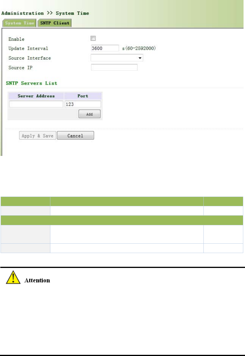
Fromtheleftnavigationpanel,selectAdministration/SystemTime,thenenter“SNTPClient”
page,asshowninFigure3‐5.
Figure3‐5SNTPClientPort
PagedescriptionisshowninTable3‐1.
Table3‐1SNTPClientPortPageDescription
ParameterDescriptionDefault
SourceIPThecorrespondingIPofsourceinterfaceNone
SNTPServersList
ServerAddressSNTPserveraddress(domainname/IP),maximumto
set10SNTPserverNone
PortTheserviceportofSNTPserver123
BeforesettingaSNTPserver,shouldensureSNTPserverreachable.EspeciallywhentheIP
addressofSNTPserverisdomain,shouldensureDNSserverhasbeenconfigured
correctly.
Ifyouconfigureasourceinterfaceandthencannotconfigurethesourceaddress.the
oppositeisalsotrue.
WhensettingmultipleSNTPserver,systemwillpollallSNTPserversuntilfindanavailableSNTP
server.
3.2.3AdminAccess
AdminAccessallowsthemanagementofuserswhicharecategorizedintosuperuserand
commonuser.
Superuser:onlyoneautomaticallycreatedbythesystem,allocatedwiththeusername
ofadmandgrantedwithallaccessrightstotherouter.
Commonuser:createdbysuperuserwiththerighttocheckratherthenmodifyrouter
configuration.
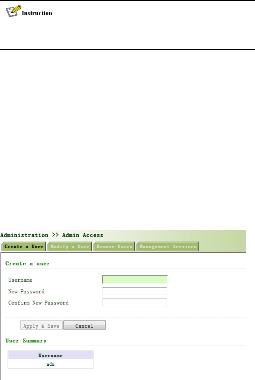
3.2.3.1Createauser
Clicknavigationpanel/AdminAccess,enter“Createauser”page,Whereintheuserpermissions
value,thehighertheprivilege,showninFigure3‐6.
Figure3‐6Createauser
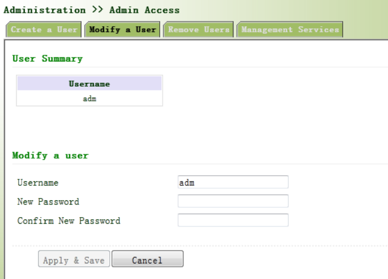
3.2.3.2ModifyaUser
Fromtheleftnavigationpanel,selectAdministration/AdminAccess,thenenter“ModifyaUser”
page,asshowninFigure3‐7.Presstheuserthatneedstomodifyin“UserSummary”,afterthe
backgroundturnsblue,enternewinformationin“ModifyaUser”.
Figure3‐7ModifyaUser
3.2.3.3RemoveUsers
Fromtheleftnavigationpanel,selectAdministration/AdminAccess,thenenter“RemoveUsers”
page,asshowninFigure3‐8.
Presstheuserthatneedstoremovein”UserSummary”.Afterthebackgroundturnsblue,press
<Delete>toremovetheuser.
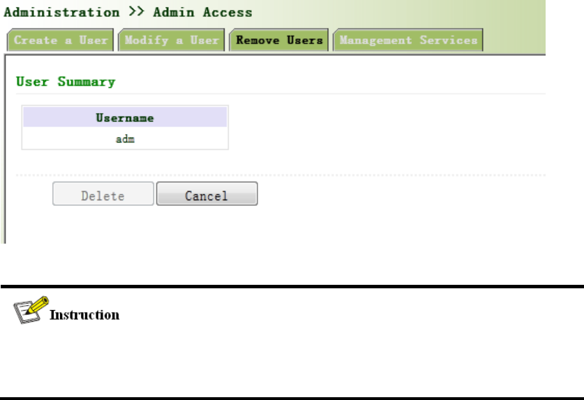
Figure3‐8RemoveUsers
Thesuperuser(adm)canneitherbemodifiednordeleted.Butsuperuser’spasswordcanbe
modified.
3.2.3.4ManagementService
HTTP
HTTP,shortenedformofHypertextTransferProtocol,isusedtotransmitWebpageinformation
onInternet.HTTPislocatedastheapplicationlayerinTCP/IPprotocolstack.
ThroughHTTP,usercouldlogonthedevicetoaccessandcontrolitthroughWeb.
HTTPS
HTTPS(HypertextTransferProtocolSecure)supportsHTTPinSSL(SecuritySocketLayer).
HTTPS,dependingonSSL,isabletoimprovethedevice’ssecuritythroughfollowingaspects:
DistinguishlegalclientsfromillegalclientsthroughSSLandDisableillegalclientsto
accessthedevice;
Encryptthedataexchangedbetweenclientanddevicetoguaranteesecurityand
integralityofdatatransmissionsoastoachievethesafemanagementofdevice;
Anaccesscontrolstrategybasedoncertificateattributionsisestablishedforfurther
controlofclient’saccessauthoritysoastofurtheravoidattackforillegalclients.
TELNET
Telnet isanapplicationlayerprotocolinTCP/IPprotocolfamily,providingtelnetandVTfunctions
throughWeb.DependingonServer/Client,Tel netClientcouldsendrequesttoTelnetserver
whichprovidesTeln etservices.ThedevicesupportsTel netClientandTe lnetServer.
SSH
IncomparisonwithTel net, STelnet(SecureTel net) ,basedonSSH2,allowstheClienttonegotiate
withServersoastoestablishsecureconnection.ClientcouldlogonServerjustasoperationof
Telnet .
ThroughfollowingmeasuresSSHwillrealizethesecuretelnetoninsecurenetwork:
SupportRASauthentication.
SupportencryptionalgorithmssuchasDES,3DESandAES128toencrypt
usernamepasswordanddatatransmission.
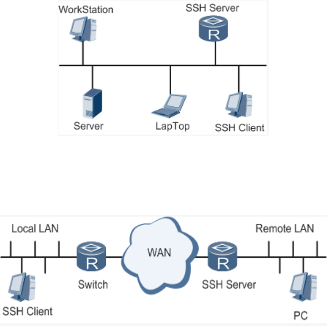
Localconnection.ASSHchannelcouldbeestablishedbetweenSSHClientandSSH
Servertoachievelocalconnection.Followingisafigureshowingthe
establishmentofaSSHchannelinLAN:
WANconnection.ASSHchannelcouldbeestablishedbetweenSSHClientandSSH
ServertoachieveWANconnection.Followingisafigureshowingtheestablishmentofa
SSHchannelinWAN:
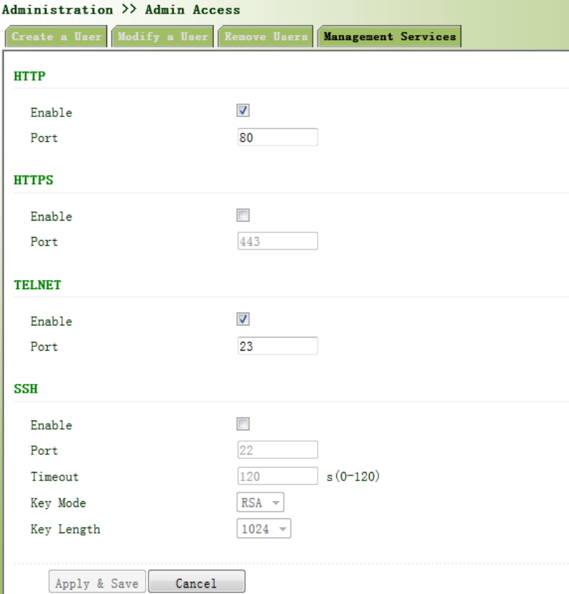
Fromtheleftnavigationpanel,selectAdministration/AdminAccess,thenenter“Management
Service”page,asshowninFigure3‐9.
Figure3‐9ManagementService
3.2.4AAA
AAAaccesscontrolisusedtocontrolvisitorsandcorrespondingservicesavailableaslongas
accessisallowed.Samemethodisadoptedtoconfigurethreeindependentsafetyfunctions.It
providesmodularizationmethodsforfollowingservices:
Authentication:verifywhethertheuserisqualifiedtoaccesstothenetwork.
Authorization:relatedwithservicesavailable.
Charging:recordsoftheutilizationofnetworkresources.。
UsermayonlyuseoneortwosafetyservicesprovidedbyAAA.Forexample,thecompanyjust
wantsidentityauthenticationwhenemployeesareaccessingtosomespecifiedresources,then
networkadministratoronlyneedstoconfigureauthenticationserver.Butifrecordingofthe
utilizationofnetworkisrequired,then,achargingservershallbeconfigured.
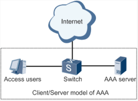
CommonlyAAAadopts“Client—Server”structurewhichisfeaturedbyfavorableexpandability
andfacilitatescentralizedmanagementofusers’information,asthefollowingfigureshows:
3.2.4.1Radius
RemoteAuthenticationDial‐inUserService(RADIUS),aninformationexchangeprotocolwitha
distributiveClient/Serverstructure,couldpreventthenetworkfromanydisturbancefrom
unauthorizedaccessandisgenerallyappliedinvariousnetworkenvironmentswithhigher
requirementsonsecurityandthatpermitremoteuseraccess.Theprotocolhasdefinedthe
RadiusframeformatbasedonUDPandinformationtransmissionmechanism,confirmedUDP
Port1812astheauthenticationport.RadiusServergenerallyrunsoncentralcomputeror
workstation;RadiusClientgenerallyislocatedonNAS.
InitiallyRadiusisdesignedanddevelopedagainstAAAprotocolofdial‐inusers.Alongwiththe
diversifieddevelopmentofuseraccessways,Radiusalsoadaptsitselftosuchchanges,including
EthernetaccessandADSLaccess.Accessserviceisrenderedthroughauthenticationand
authorization.
MessageflowbetweenRadiusClientandServerisshownasfollows:
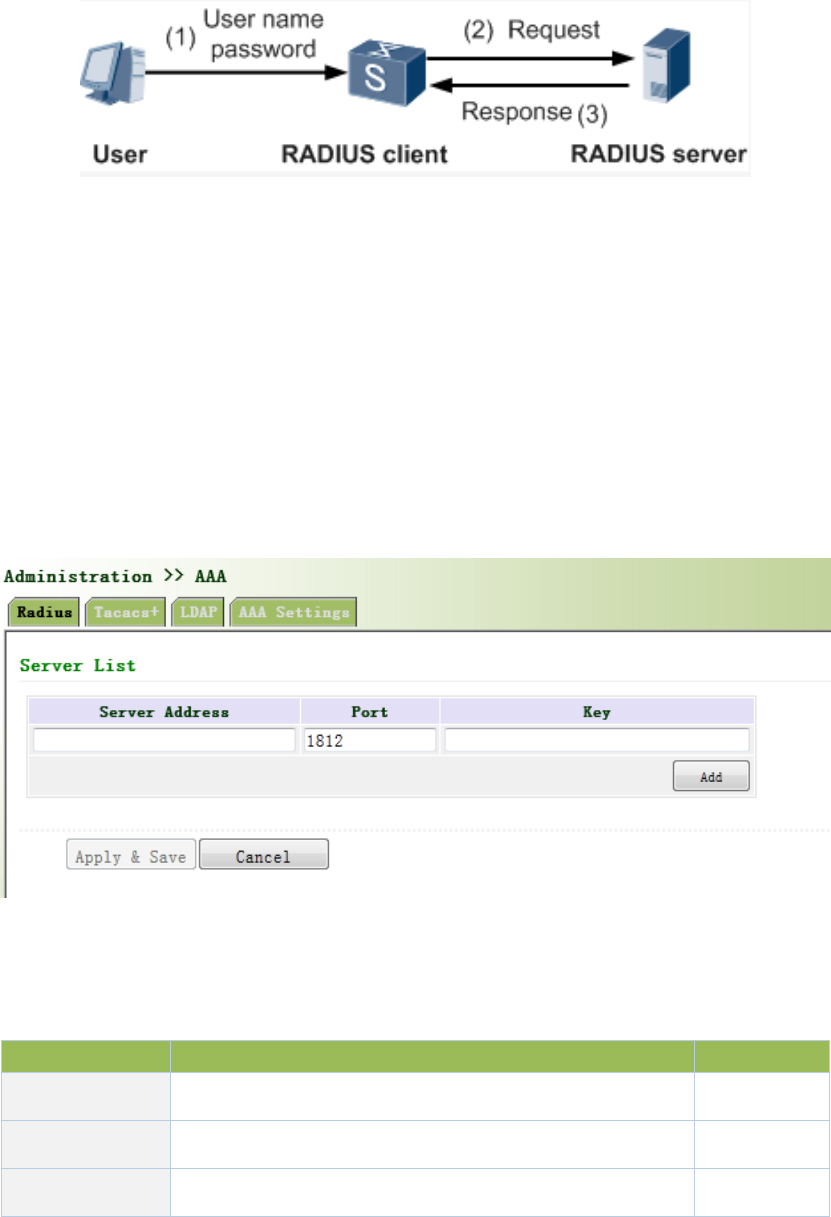
UsernameandpassportwillbesenttotheNASwhentheuserlogsonit;
RadiusClientonNASreceivesusernameandpasswordandthensendsan
authenticationrequesttoRadiusServer;
Uponthereceptionoflegalrequest,RadiusServerexecutesauthenticationandfeeds
backrequireduserauthorizationinformationtoClient;Forillegalrequest,Radius
ServerwillfeedbackAuthenticationFailedtoClient.
Fromtheleftnavigationpanel,selectAdministration/AAA,thenenter“Radius”page,asshownin
Figure3‐10.
Figure3‐10Radius
PagedescriptionisshowninTable3‐2.
Table3‐2RadiusDescription
ParameterDescriptionDefault
ServerAddressServeraddress(domainname/IP)None
PortConsistentwiththeserverport1812
KeyConsistentwiththeserverauthenticationkeyNone
3.2.4.2Tacacs+
Tacacs+,orTerminalAccessControllerAccessControlSystem,similartoRadius,adopts
Client/ServermodetoachievethecommunicationbetweenNASandTacacs+Server.But,Tacacs+
adoptsTCPwhileRadiusadoptsUDP.
Tacacs+ismainlyusedforauthentication,authorizationandchargingofaccessusersandterminal
usersadoptingPPPandVPDN.Itstypicalapplicationisauthentication,authorizationandcharging
forterminalusersrequiringloggingonthedevicetocarryoutoperation.AstheClient,thedevice
willhaveusernameandpasswordsenttoTacacs+Serverforverification.Solongasuser
verificationpassedandauthorizationobtained,loggingandoperationonthedeviceareallowed.
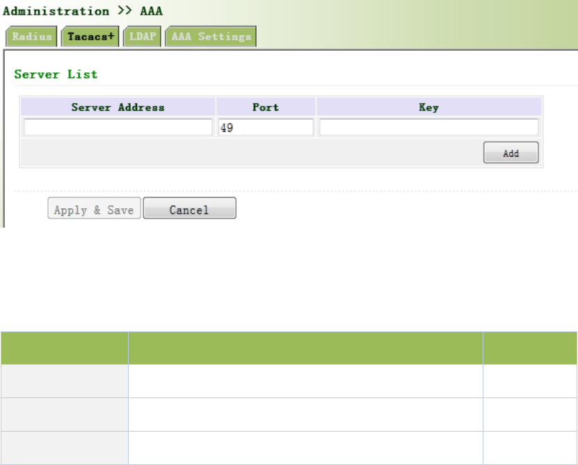
Fromtheleftnavigationpanel,selectAdministration/AAA,thenenter“Tacacs+”page,asshown
inFigure3‐11.
Figure3‐11Tacacs+
PagedescriptionisshowninTable3‐3.
Table3‐3Tacacs+Description
ParametersDescriptionDefault
ServerAddressServeraddress(domainname/IP)None
PortConsistentwiththeserverport49
KeyConsistentwiththeserverauthenticationkeyNone
3.2.4.3LDAP
OneofthegreatadvantagesofLDAPisrapidresponsetousers’searchingrequest.Forinstance,
user’sauthenticationwhichmaygeneralalargeamountofinformationsentasthesametime.If
databaseisadoptedforthispurpose,sinceitisdividedintomanytables,eachtimetomeetsuch
asimplerequirement,thewholedatabasehastobesearched,integratedandfilteredslowlyand
disadvantageously.LDAP,simpleasatable,onlyrequiresusernameandcommandandsomething
else.Authenticationismetfromefficiencyandstructure.
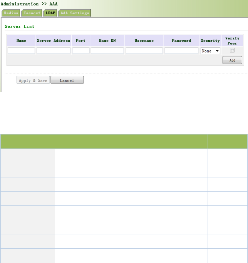
Fromtheleftnavigationpanel,selectAdministration/AAA,thenenter“LDAP”page,asshownin
Figure3‐12.
Figure3‐12LDAP
PagedescriptionisshowninTable3‐4.
Table3‐4LDAPDescription
ParametersDescriptionDefault
Name DefineservernameNone
ServerAddressServeraddress(domainname/IP)None
PortConsistentwiththeserverportNone
BaseDNThetopofLDAPdirectorytreeNone
UsernameUsernameaccessingtheserverNone
PasswordPasswordaccessingtheserverNone
Security Encryptionmod:None,SSL,StartTLSNone
VerifyPeer VerifyPeerUnopened
3.2.4.4AAASettings
AAAsupportsfollowingauthenticationways:
None:withgreatconfidencetousers,legalcheckomitted,generallynotrecommended.
Local:Haveuser’sinformationstoredonNAS.Advantages:rapidness,costreduction.
Disadvantages:storagecapacitylimitedbyhardware.
Remote:Haveuser’sinformationstoredonauthenticationserver.Radius,Tacacs+and
LDAPsupportedforremoteauthentication.
AAAsupportsfollowingauthorizationways:
None:authorizationrejected.
Local:authorizationbasedonrelevantattributionsconfiguredbyNASforlocaluser’s
account.
Tacacs+:authorizationdonebyTacacs+Server.
RadiusAuthenticationBased:authenticationbondedwithauthorization,authorization
onlybyRadiusnotallowed.
LDAPAuthorization.
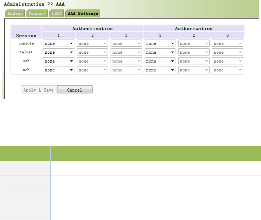
Fromtheleftnavigationpanel,selectAdministration/AAA,thenenter“AAASetting”page,as
showninFigure3‐13.
Figure3‐13AAAauthentication
PagedescriptionisshowninTable3‐5.
Table3‐5AAASettingsKeyItems
KeyItemsDescription
radiusAuthenticationandAuthorizationServer
tacacs+AuthenticationandAuthorizationServer
ldapAuthenticationandAuthorizationServer
local Thelocalusernameandpassword
Authentication1shouldbesetconsistentlywithAuthorization1;Authentication2shouldbe
setconsistentlywithAuthorization2;Authentication3shouldbesetconsistentlywith
Authorization3.
Whenconfigureradius,Tacas+,localatthesametime,priorityorderfollow:1>2>3.
3.2.5ConfigurationManagement
Hereyoucanbackuptheconfigurationparameters,importthedesiredparametersconfiguration
backupandrestorethefactorysettingsoftherouter.
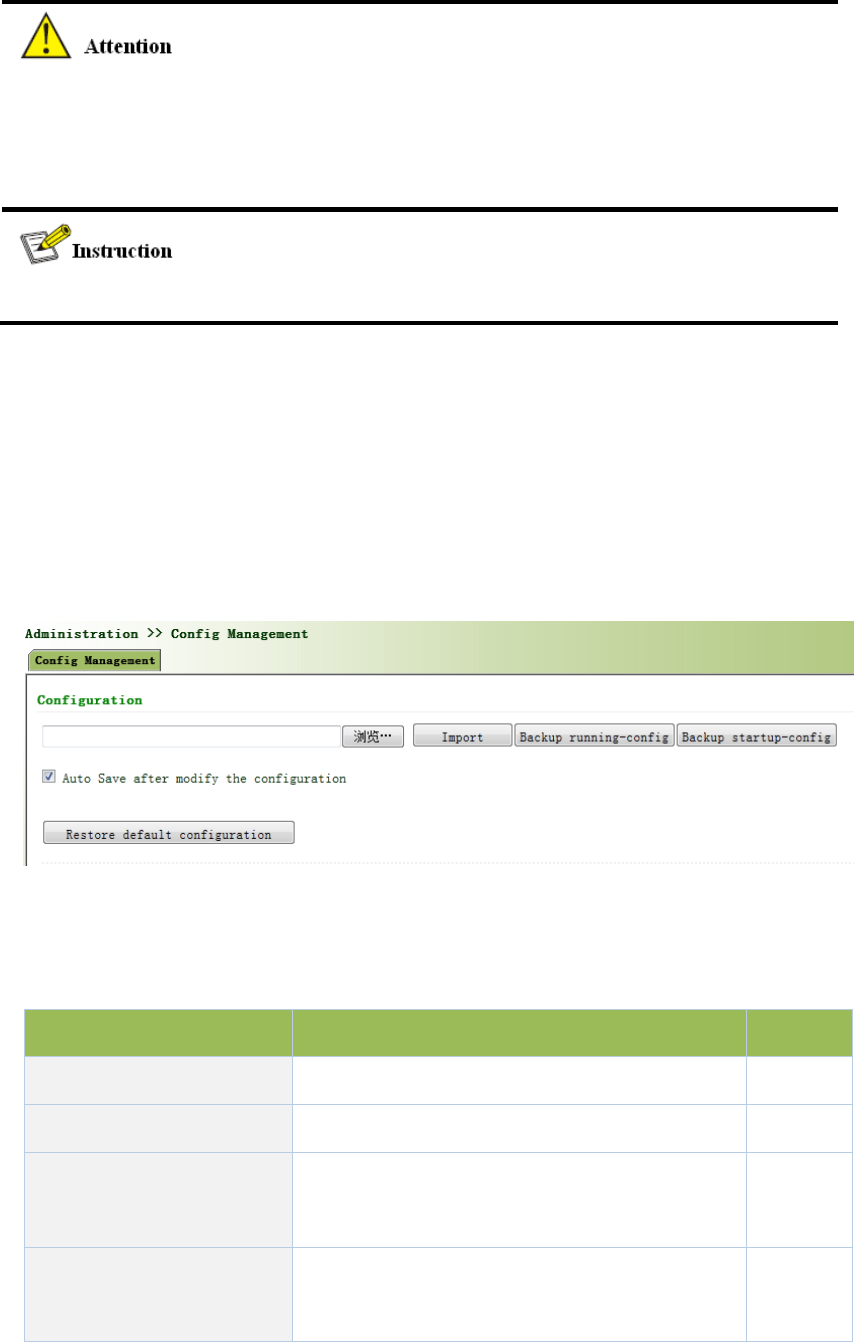
Fromtheleftnavigationpanel,selectAdministration/ConfigManagement,thenenter“Config
Management”page,asshownin3‐14.
Figure3‐14ConfigurationManagement
PagedescriptionisshowninTable3‐6.
Table3‐6ConfigManagementDescription
ParametersDescriptionDefault
Backuprunning‐configBackuprunning‐configfiletohost.None
Backupstartup‐configBackupstartup‐configfiletohost.None
Automaticallysavemodified
configuration
Decidewhethertoautomaticallysave
configurationaftermodifytheconfiguration.
On
RestoreDefault
Configuration
RestorefactoryconfigurationNone

Whenimporttheconfiguration,thesystemwillfilterincorrectconfigurationfiles,andsavethe
correctconfigurationfiles,whensystemrestarts,itwillorderlyexecutethesesconfiguration
files.Iftheconfigurationfilesdidn’tbearrangedaccordingtoeffectiveorder,thesystemwon’t
enterthedesiredstate.
Inordernottoaffectcurrentsystemrunning,whenperformingtheimportconfigurationand
restorethedefaultconfiguration,needtoreboottherouternewconfigurationwilltakeeffect.
3.2.6SNMP
Definition
SNMP,orSimpleNetworkManagementProtocol,isastandardnetworkmanagementprotocol
widelyusedinTCP/IPnetworksandprovidesamethodofmanagingthedevicethroughthe
runningthecentralcomputerofnetworkmanagementsoftware.FeaturesofSNMP:
Simplicity:SNMPadoptspollingmechanism,providesthemostbasicsetsoffeatures
andcouldbeusedinsmall‐scale,rapid,lowcostenvironments.SNMP,withUDP
messageasthecarrier,issupportedbyagreatmajorityofdevices.
Powerfulness:objectiveofSNMPistoensurethetransmissionofmanagement
informationbetweenanytwopointssoastofacilitateadministrator’sretrievalof
informationonanynodeonnetworkandmodificationandtroubleshooting.
Benefits
NetworkadministratorscouldmakeuseofSNMPtoaccomplishtheinformationquery,
modification,troubleshootingandotherjobsonanynodeonnetworktoachieve
higherefficiency.
Shieldingofphysicaldifferencesbetweendevices.SNMPonlyprovidesthemostbasic
setsoffeaturesformutualindependencebetweenadministrationandthephysical
properties,networktypesofdevicesunderadministration;therefore,itcouldrealize
theuniformmanagementofdifferentdevicesatalowercost.
Simpledesign,lowercost.Simplicityisstressedonadditionofsoftware/hardware,
typesandformatsofmessageondevicessoastominimizetheinfluenceandcoston
devicescausedbyrunningSNMP.
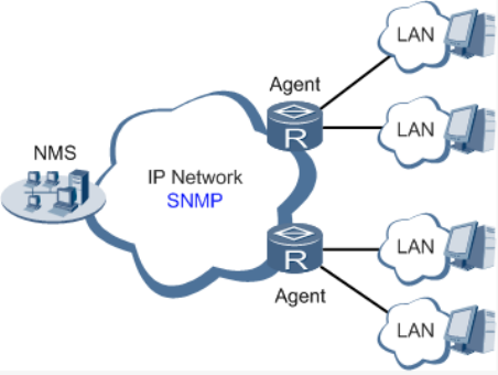
Application:managementofdeviceisachievedthroughSNMP
Administratorisrequiredtocarryoutconfigurationandmanagementofalldevicesinthesame
network,whicharescattered,makingonsitedeviceconfigurationimpracticable.Moreover,in
casethatthosenetworkdevicesaresuppliedfromdifferentsourcesandeachsourcehasits
independentmanagementinterfaces(forexample,differentcommandlines),theworkloadof
batchconfigurationofnetworkdeviceswillbeconsiderable.Therefore,undersuchcircumstances,
traditionalmanualwayswillresultinlowerefficiencyathighercost.Atthattime,network
administratorwouldmakeuseofSNMPtocarryoutremotemanagementandconfigurationof
attacheddevicesandachievereal‐timemonitoring.Followingisafigureshowinghowtomanage
devicesthroughSNMP:
ToconfigureSNMPinnetworking,NMS,amanagementprogramofSNMP,shallbeconfiguredat
theManager.Meanwhile,Agentshallbeconfiguredaswell.
ThroughSNMP:
NMScouldcollectstatusinformationofdeviceswheneverandwhereverandachieve
remotecontrolofdevicesundermanagementthroughAgent.
AgentcouldtimelysendcurrentstatusinformationtoNMSreportdevice.Incaseofany
problem,NMSwillbenotifiedimmediately.
3.2.6.1SNMP
SNMPagentofdevicesupportsSNMPv1,SNMPv2andSNMPv3atpresent.
SNMPv1andSNMPv2adoptcommunitynametoauthenticate.
SNMPv3adoptusernameandpasswordtoauthenticate.
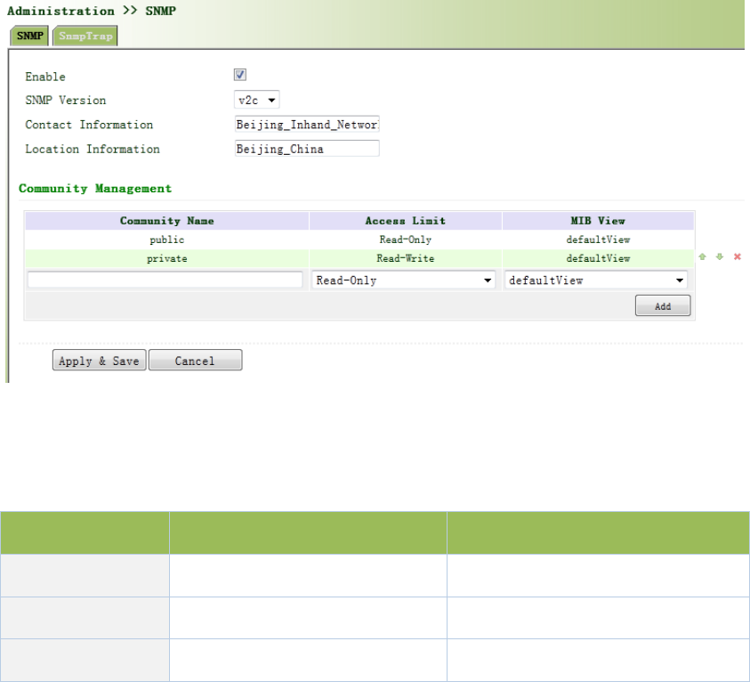
Fromtheleftnavigationpanel,selectAdministration/SNMP,thenenter“SNMP”page,as
showninFigure3‐15.
Figure3‐1SNMPv1&SNMPv2cSettings
PagedescriptionisshowninTable3‐7.
Table3‐7SNMPKeyItems
ParametersDescriptionDefault
CommunityNameUserdefineCommunityNamePublicandprivate
AccessLimitSelectaccesslimitRead‐only
MIBView SelectMIBViewdefaultView
WhenchoosingSNMPv3version,thecorrespondingUseandUserGroupshouldbeconfigured.
TheconfigurationpageisshowninFigure3‐16.
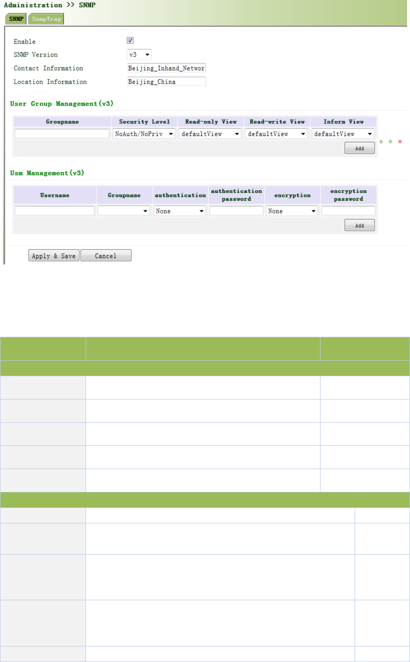
Figure3‐16SNMPv3Setting
PagedescriptionisshowninTable3‐8.
Table3‐8SNMPv3Description
ParametersDescriptionDefault
GroupManagement
GroupnameUserdefine,length:1‐32charatersNone
SecurityLevelIncludesNoAuth/NoPriv,Auth/NoPriv,Auth/privNoAuth/NoPriv
Read‐onlyViewOnlysupportdefaultViewatpresentdefaultView
Read‐writeViewOnlysupportdefaultViewatpresentdefaultView
InformViewOnlysupportdefaultViewatpresentdefaultView
UserManagement
UsernameUser‐definedusername,length:1‐32charactersNone
GroupNameSelectusertojoinusergroup,firstdefinedintheusergroup
managementtable,beforethis,selectappropriateusergroupNone
Authentication
Mode
Selectauthenticationmode.MD5andSHAprovidestwo
authenticationmodes,“noidentification"notenable
authentication.
SHA
Authentication
password
Whenonlyauthenticationmodeisnot"noidentification",
authenticationpasswordcanenter.
Length:8‐32characters.
None
EncryptionmodeChoosewhethertouseDESencryptionmodeDES
Encryption
Password
Onlyencryptionmodeisnot"noencryption",encryption
modepasswordcanenter.
Length:8‐32characters.
None
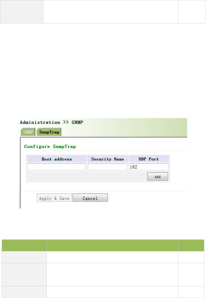
3.2.6.2SnmpTrap
SNMPtrap:AcertainportwheredevicesunderthemanagementofSNMPwillnotifySNMP
managerratherthanwaitingforpollingfromSNMPmanager.InNMS,Agentsinmanageddevices
couldhaveallerrorsreportedtoNMWatanytimeinsteadofwaitingforpollingfromNMWafter
itsreceptionofsucherrorswhich,asamatteroffact,arethewell‐knownSNMPtraps.
Fromtheleftnavigationpanel,selectAdministration/SNMP,thenenter“SnmpTrap”page,as
showninFigure3‐17.
Figure3‐17SnmpTrap
PagedescriptionisshowninTable3‐9.
Table3‐9SnmpTrapDescription
ParametersDescriptionDefault
HostAddressFillintheNMSIPaddressNone
SecurtiyName
FillinthegroupnamewhenusetheSNMPv1/v2c;Fillinthe
usernamewhenusetheSNMPv3.Length:1‐32characters
None
UDPPort FillinUDPport,thedefaultportrangeis1‐65535162
3.2.7Alarm
Alarmfunctionisawaywhichisprovidedforuserstogetexceptionsofdevice,whichcanmake

theusersfindandsolveexceptionsassoonaspossible.Whenabnormalityhappened,devicewill
sendalarm.Usercanchoosemanykindsofexceptionswhichsystemdefinedandchoose
appropriatenoticewaytogettheseexceptions.Alltheexceptionsshouldberecordedinalarm
logsothatusertroubleshootproblem.
Alarmcanbedivided:
Raise:Indicatesthealarmoccurrencehasnotbeenconfirmed.
Confirm:Alarmindicatesthatausercannottemporarysolve.
All:Indicatesallalarmsoccur.
Alarmlevelcanbedivided:
EMERG:Deviceoccurssomefaults,itcouldleadtothesystemrestart.
CRIT:Deviceoccurssomefaultswhichareunrecoverable.
WARN:Deviceoccurssomefaultswhichcouldaffectsystemfunction.
NOTICE:Deviceoccurssomefaultswhichcouldaffectsystemproperties.
INFO:Deviceoccurssomenormalevents.
3.2.7.1AlarmStatus
Fromtheleftnavigationpanel,selectAdministration/Alarm,thenenter“AlarmState”page,as
showninFigure3‐18.Throughthispage,youcancheckallthealrmssincetherouterispowered.
Click<ClearAllAlarms>tosetallthealarmto“clear”state.
Click<ConfirmAllAlarms>tosetallthealarmto“cconfirm”state.
Click<Reload>toreloadallthealarms.
Figure3‐18AlarmStatus
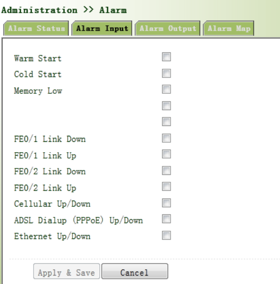
3.2.7.2AlarmInput
Hereusercouldselectalarmtypesincludingsystemalarmandportalarm.Oneormorethanone
typescouldbeselected.
Fromtheleftnavigationpanel,selectAdministration/Alarm,thenenter“AlarmInput”page,as
showninFigure3‐19.
Figure3‐19AlarmInput
3.2.7.3AlarmOutput
Whenanalarmhappens,thesystemconfiguredwiththisfunctionwillsendthealarmcontentto
intendedemailaddressfromthemailaddresswhereanalarmemailissentinaformofemail.
Generallythisfunctionisnotconfigured.
Fromtheleftnavigationpanel,selectAdministration/Alarm,thenenter“AlarmOutput”page,as
showninFigure3‐20.
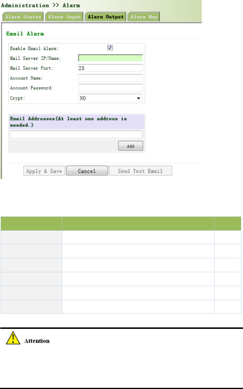
Figure3‐20AlarmOutput
PagedescriptionisshowninTable3‐10.
Table3‐10AlarmOutputDescription
ParametersDescriptionDefault
MailServerIP/NameSetIPaddressofMailServerthatsendalarmemails None
MailServerPortSetPortofMailServerthatsendalarmemails25
AccountName SetEmailaddressfromwhichalarmemailsaresentNone
AccountPassword SetEmailpassword None
CryptSetthecryptmethodNone
EmailAddressesDestinationaddressofreceivingalarmemail(1‐10)None
Whentheemailparametershadbeenconfigured,youshouldclickthe“sendtestemail”button
sothatensuretheconfigurationiscorrect.Ifthetestemailfailed,itmaythenetwork
configurationormailboxconfigurationisnotcorrect.
3.2.7.4AlarmMap
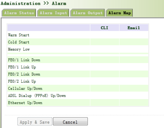
AlarmMapconsistsoftwomappingways:CLI(consoleinterface)andEmail.Incaseoflatterone
isselected,andthenalarmoutputshallbeactivatedwithanemailaddresswellconfigured.
Fromtheleftnavigationpanel,selectAdministration/Alarm,thenenter“AlarmMap”page,as
showninFigure3‐21.
Figure3‐21AlarmMap
3.2.8SystemLog
SystemLogincludesmassiveinformationaboutnetworkanddevices,includingoperatingstatus,
configurationchangesandsoon,servingasanimportantwayfornetworkadministratorto
monitorandcontroltheoperationofnetworkanddevices.SystemLogcouldprovideinformation
tohelpnetworkadministratortofindnetworkproblemsorsafetyhazardsoastotakemore
targetedmeasures.
3.2.8.1SystemLog
Fromtheleftnavigationpanel,selectAdministration/Log,thenenter“SystemLog”page,as
showninFigure3‐22.
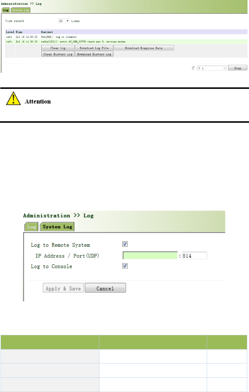
Figure3‐22SystemLog
Whendownloadsystemlog,routersettingswillalsobedownloaded.
3.2.8.2SystemLogSettings
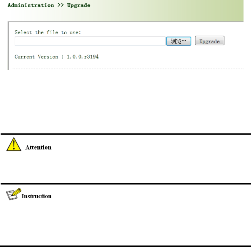
On“SystemLogSettings”,remotelogservercouldbeset.Routerwillhaveallsystemlogssentto
remotelogserverdependingonremotelogsoftware(forexample:KiwiSyslogDaemon).
Fromnavigationpanel,selectAdministration/Log,thenenter“SystemLog”page,asshownin
Figure2‐23.
Figure3‐23SystemLogSettings
PagedescriptionisshowninTable3‐11.
Table3‐11SystemLogSettingsDescription
ParametersDescriptionDefault
LogtoRemoteSystemOpen/closeremotelogfunctionClose
IPAddress/Port(UDP)Setremoteserver’sIPaddress/PortNone/514
LogtoConsoleOpen/closeconsolelogfunctionOpen
3.2.8.3KiwiSyslogDaemon
KiwiSyslogDaemonisakindoffreelogserversoftwareusedinWindows,whichcouldreceive,
recordanddisplaylogsformedwhenpoweringonthehostofsyslog(forexample,router,
exchangeboard,Unixhost).AfterdownloadingandinstallationofKiwiSyslogDaemon,configure
necessaryparameterson“File>>Setup>>Input>>UDP”.
3.2.9SystemUpgrading
Fromnavigationpanel,selectAdministration/Upgrade,thenenter“Upgrade”page,asshownin
Figure3‐24.
Figure3‐24SystemUpgrading
Click<Browse>toupgradedocumentsandthenclick<Upgrade>tostart.Thewholeprocess
takesabout1min,uponthecompletionofwhich,restarttherouterandnewfirmwaretakes
effect.
Softwareupgradetakestime,duringwhich,pleasedonocarryoutanyoperationonWeb,
otherwise,interruptionmaytakeplace.
Upgradeconsistsoftwostages:firststage:read‐inofupgradedocumentintobackupfirmware
zone,asdescribedinSectionofSystemUpgrade;secondstage:copyofdocumentsinbackup
firmwarezoneintomainfirmwarezone,whichmaybeexecutedinsystemreboot.

3.2.10Reboot
Fromnavigationpanel,selectAdministration/Reboot,thenenter“Reboot”page,asshownin
Figure3‐25.Click<Yes>torebootthesystem.
Figure3‐25Reboot
Pleasesavetheconfigurationsbeforereboot,otherwisetheconfigurationsthatarenotsaved
willbelostafterreboot.
3.2.11CloudPlatform
Cloudplatformisthroughsoftwareplatformtomanagedevices.Afterenablingcloudplatform,it
canoperatethedevicemanagementthroughsoftwareplatformthatenablesnetwork‐efficient
running.Forexample,queryequipmentrunningstatus,updatethedevicesoftware,rebootthe
device,andsendconfigurationparameterstotheequipment,etc.,mayalsosendcontrolor
querymessagetothedevicethroughthecloudplatform.
3.2.11.1CloudPlatform
Fromnavigationpanel"Administration>>DeviceManagementCloud"menu,enterthe"Cloud
Platform"screen,asshowninFigure3‐26.
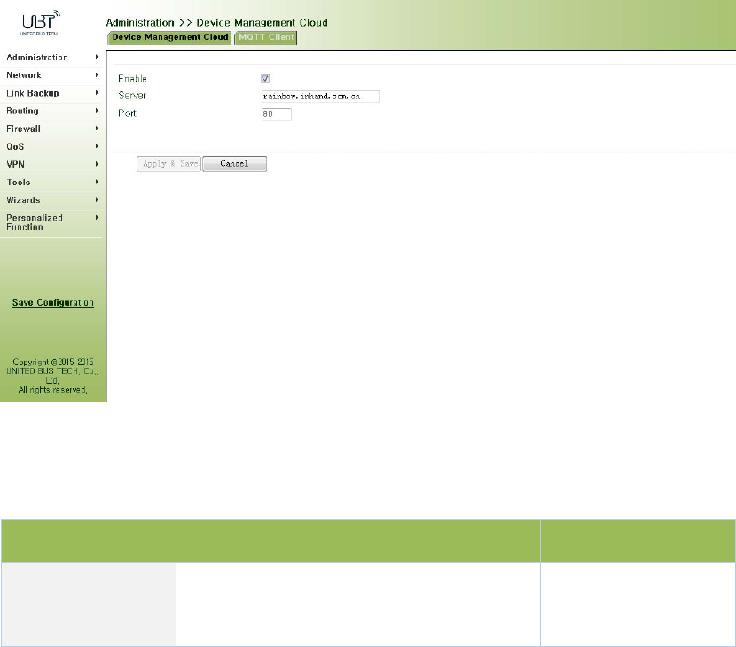
Figure3‐26CloudPlatform
PagedescriptionisshowninTable3‐12.
Table3‐12CloudPlatformDescription
ParametersDescriptionDefault
Server SetcloudplatformIPaddress none
PortSettingcloudplatformportnumbernone
3.2.11.2MOTTClient
Fromnavigationpanel“Administration>>DeviceManagementCloud"menu,enterthe"MOTT
Client"screen,asshownbelow.
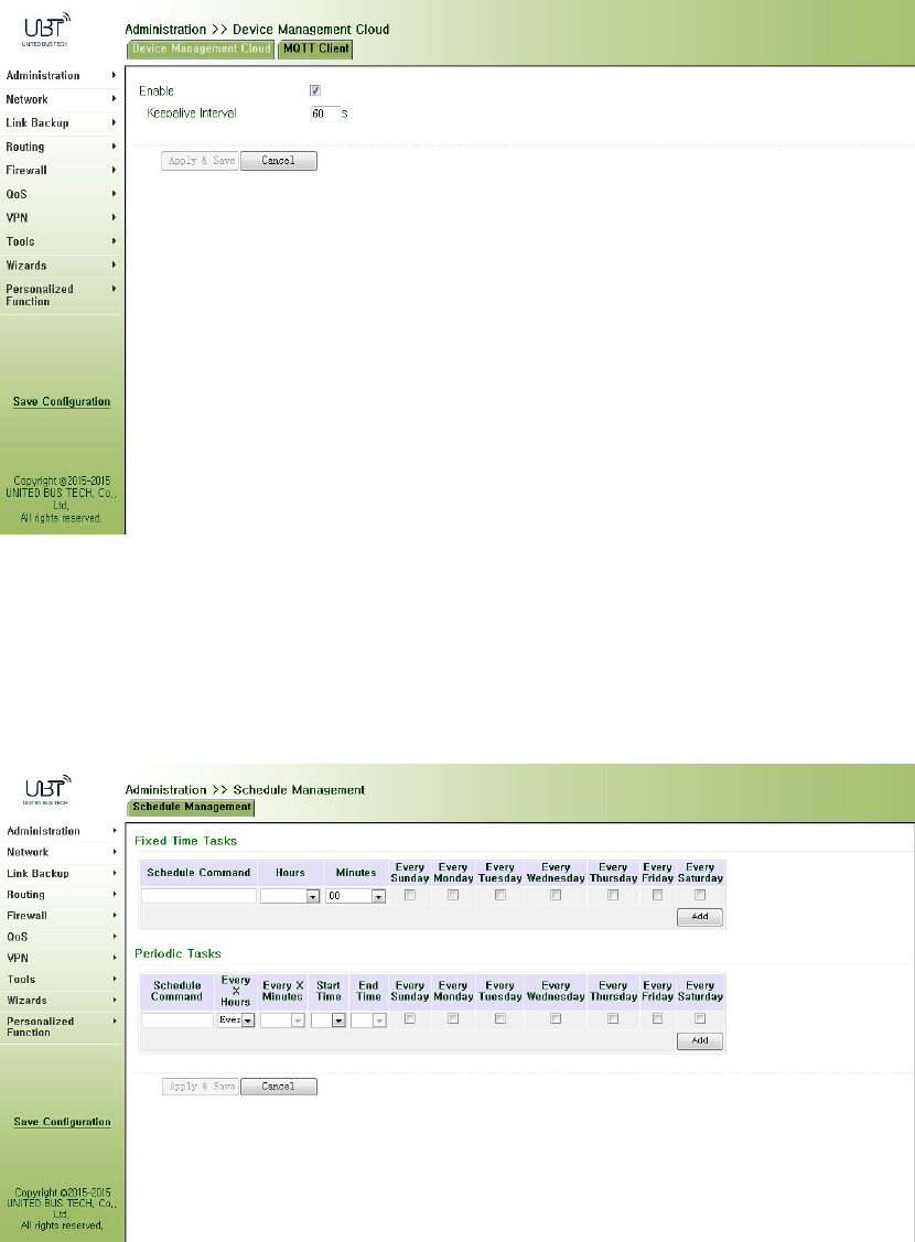
3.2.12ScheduledTasks
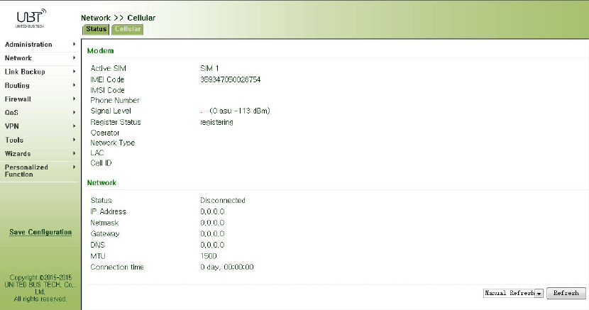
Fromnavigationpanel,selectAdministration>>ScheduleManagement,thenenter“Schedule
Management”page,asshowninFigure3‐27.
Figure3‐27ScheduleManagement
3.3Network
3.3.1Cellular
SIMcarddialoutthroughDialInterface,achieverouterWi‐Ficapabilities.
Dialinterfacesupportsthreeconnections:always‐on,on‐demanddialingandmanualdialing.
3.3.1.1Status
Fromnavigationpanel,selectNetwork>>Cellular,thenenter“Status”page,asshowninFigure
3‐28.
Figure3‐28Status
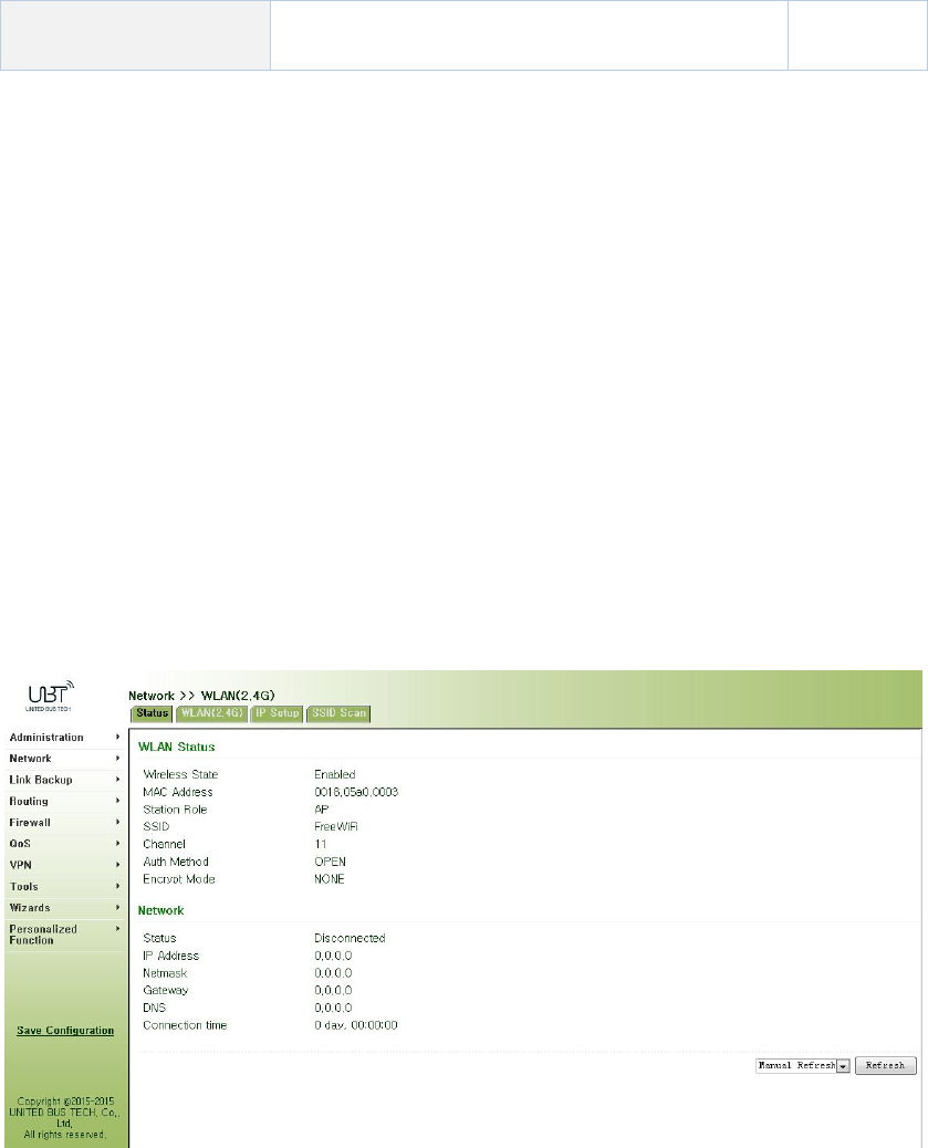
3.3.1.2Cellular
Inthe"Cellular"page,youcancompletethewirelessdialconfiguration.
Fromnavigationpanel,selectNetwork>>Cellular,thenenter“Cellular”page,asshowninFigure
3‐29‐1.
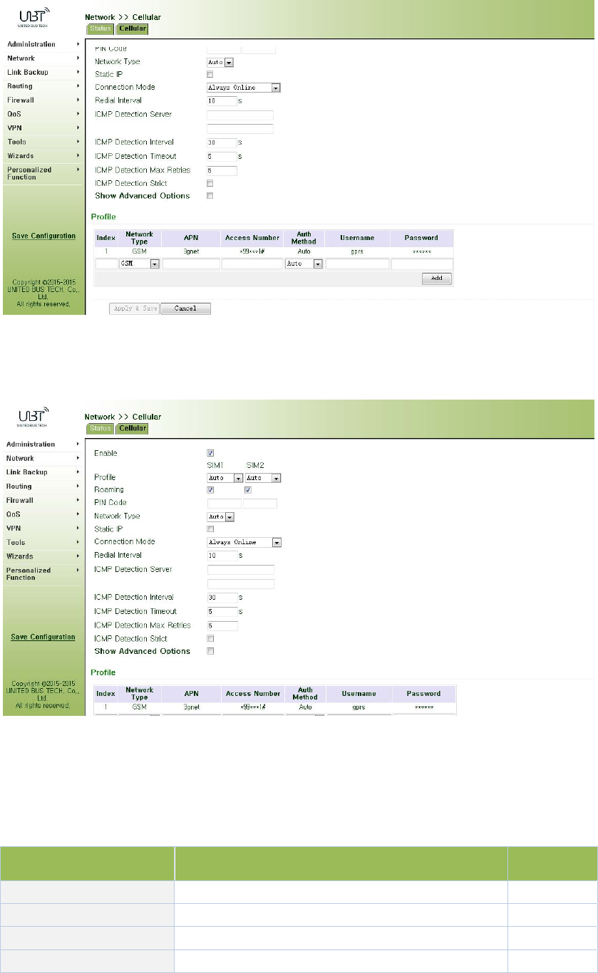
Figure3‐29‐1Cellular
AdvancedoptionsareshowninFigure3‐29‐2.
Figure3‐29‐2CellularAdvancedoptions
PagedescriptionisshowninTable3‐13.
Table3‐13CellularPageDescription
ParametersDescriptionDefault
ProfileDialpolicychoices,donotneedtoconfigurehere1
RoamingSelectroamingEnable
PINCodeSIMcardPINcodeNone
NetworkSelectionModeThreeoptions:Automatic,2Gand3GAuto

StaticIPClickEnable(Enablerequireoperatorstoopen
relatedservices)Off
Connection
Alternativelyalwaysonline,on‐demanddial(allows
dataactivation,phoneactivation,SMSactivation),
manualdialing
Always
online
RedialIntervalwhensettingupthelandingfails,redialinginterval10sec
ICMPdetectionserverDetectremoteIPaddressNone
ICMPdetectionintervalSetICMPdetectioninterval30sec
ICMPdetectiontimeoutSetICMPdetectiontimeout5sec
ICMPdetectionmaximum
numberofretries
SetmaximumnumberofretrieswhenICMP
detectionfails(Re‐dialafterreachingthemaximum
number)
5
ICMPstrictdetectionClickEnableOff
Dialparameters
IndexUser‐defined,generallyintheorderdefinedby
digital.None
NetworkMobilenetworktypeusedforselectingGSM
APN(CDMA2000series
doesnotsetthis)
Mobileoperatorstoprovidetherelevant
parameters(accordingtolocaloperatorschoose)3gnet
DialNumberMobileoperatorstoprovidetherelevant
parameters(accordingtolocaloperatorschoose)*99***1#
UserNameMobileoperatorstoprovidetherelevant
parameters(accordingtolocaloperatorschoose)gprs
PasswordMobileoperatorstoprovidetherelevant
parameters(accordingtolocaloperatorschoose)******
ClickEnableShowAdvancedOptions(thefollowingaretherelevantparameterstoconfigure
aftertheadvancedoptionsturnon)
InitiaCommandsUsedtosetadvancednetworkparameters,
generallydonotneedtofillinNone
RSSIPollIntervalSetsignalqueryinterval120sec
DialtimeoutSetdialtimeout(afterdialingtimeoutthesystem
willredial)120sec
MTUSetsthemaximumtransmissionunitinbytes1500
MRUSettingmaximumreceivingunitinbytes1500
EnabledefaultasyncmapClickEnabledefaultasyncmapDisable
UseassignedDNSserverClicktoenabletoacceptassignedDNSbymobile
operators.Enable
Connectiondetection
intervalSetconnectiondetectioninterval55sec
ConnectionDetection
maximumnumberof
retries
Setmaximumnumberofretrieswhenconnection
detectionfails(Re‐dialafterreachingthemaximum
number)
5
EnabledebugmodeThesystemcanprintamoredetailedlogEnable
ExpertOptionsProvideadditionalPPPparameters,usersgenerally
donotsetNone
3.3.2WLANInterface(2.4G)
WLANorWirelessLAN,isquiteconvenientdatatransmissionsystem,whichusesradiofrequency
(RadioFrequency;RF)technology,toreplacetheoldoutofthewayoftwistedcopper(Coaxial)
localareanetworkcomposedofsuchawirelesslocalareanetwork,canbeaccessedusinga
simplearchitectureallowsuserstothroughit,to"carryinformationtechnologytofacilitatetravel
theworld,"theidealstate.
3.3.2.1Status
Fromnavigationpanel,selectNetwork/WLAN(2.4G),enter“Status”page,asshowninFigure
3‐30.
Figure3‐30WLAN(2.4G)Status
3.3.2.2WLAN(2.4G)
WLANinterfacehasaccesspointandclienttwotypes.Fromnavigationpanel,select
"Network/WLAN(2.4G)"menu,enter"WLAN(2.4G)"page.Interfacetypeusingthe"access
point",asshowninFigure3‐31‐a;interfacetypeusingthe"client",asshowninFigure3‐31‐b.
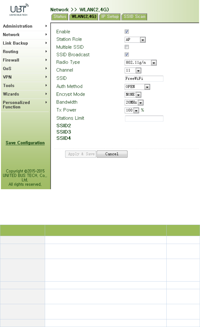
Figure3‐31‐aWLAN(2.4G)‐AccessPoint
PagedescriptionisshowninTable3‐14‐a.
Table3‐14‐aAccessPointDescription
ParametersDescriptionDefault
MultipleSSIDClickEnable,enabledreusablecustom3SSIDDisable
SSIDBroadcastOpen"SSIDBroadcast",usercansearchwirelessnetwork
throughSSIDname.Enable
RFType
SixtypesOptional:
802.11g/n,802.11g,802.11n,802.11b,802.11b/g,802.11b/
g/n
802.11g/n
Channel Selectchannel11
SSIDUser‐definedSSIDnameWIFUN10503
000
AuthenticationFourauthenticationmodesavailable:Open,Shared,
WPA‐PSKandWPA2‐PSKOpen
EncryptionAccordingtothedifferentauthenticationmethods,NONE
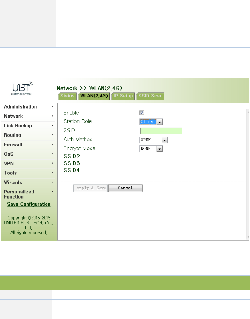
supportNONE,WEP40andWEP104
Wireless
BandwidthTwooptions:20MHzand40MHz20MHz
MaximumNumber
ofClients User‐defined(upto128)None
Figure3‐31‐bWLAN(2.4G)‐Client
PagedescriptionisshowninTable3‐14‐b.
Table3‐14‐bClientInterfaceDescription
ParametersDescriptionDefault
SSIDFillintheSSIDnametoconnectNone
AuthenticationSSIDauthenticationmethodOpen
EncryptionSSIDencryptionmethodNONE
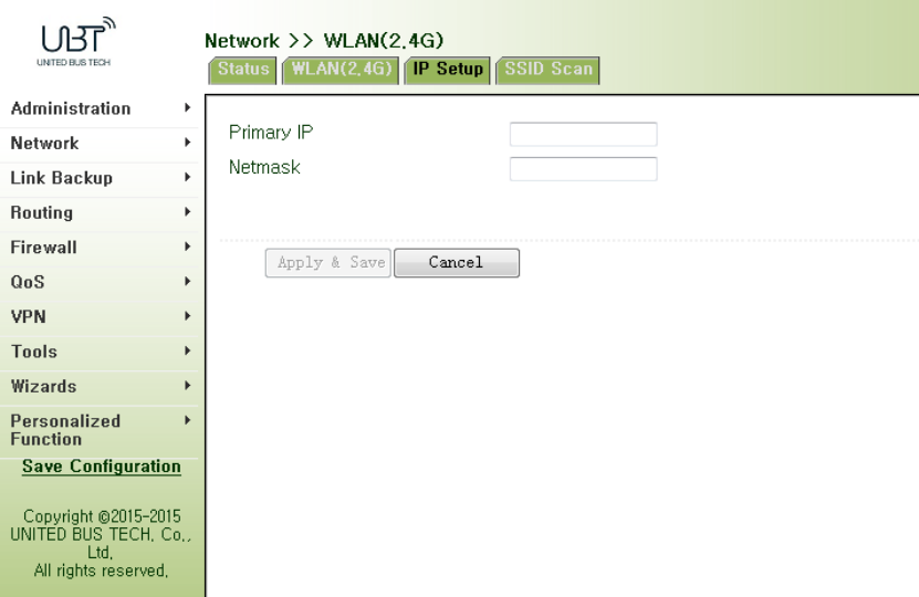
WhentheWLANissetasClientmode,refertothefollowing3steps:
Step1:select"Network/Cellular"menu,enter"Cellular"page,anddisableCellularfunction.If
therouterdoesnothavecelluarmodule,skipthisstepandgotostep2.
Step2:select"Network/WLAN(2.4G)"menu,enter"WLAN(2.4G)"pageandchoose“Client”to
configurerelatedparametersasshowninFigure3‐31‐b.
Step2:select"Network/WLAN(2.4G)"menu,enter"IPSetup"pagetoconfigureIPparametersas
shownin3.3.2.3IPSetup.
3.3.2.3IPSetup
WLANinterfaceIPaddresssupportmultipleIP,itcanbesetaccordingtodemand,butuptomore
than10.
Fromnavigationpanel,select"Network/WLAN(2.4G)"menu,enter"IPSetup"page,asshownin
Figure3‐32.
Figure3‐32WLAN(2.4G)IPSetup
3.3.2.4SSIDScan
WLANinterfaceselectsclient(Section3.3.2.2WLANInterface(2.4G)),SSIDscanningfunction
starts.Fromnavigationpanel"Network/WLAN(2.4G)"menu,enter"SSIDScan"page,willdisplay
alltheavailableSSIDnames,andthedisplayWIFUN1050canbeconnectedasaclientstate.
3.3.3WLANInterface(5.8G)
3.3.3.1Status
Fromnavigationpanel,selectNetwork/WLAN(5.8G),enter“Status”page,asshowninFigure
3‐34.
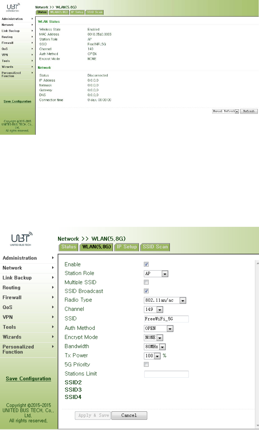
Figure3‐34WLAN(5.8G)Status
3.3.3.2WLAN(5.8G)
WLANinterfacehasaccesspointandclienttwotypes.Fromnavigationpanel"Network/WLAN
(5.8G)"menu,enter"WLAN(5.8G)"page.Interfacetypeusingthe"accesspoint",asshownin
Figure3‐35‐a;interfacetypeusingthe"client",asshowninFigure3‐35‐b.
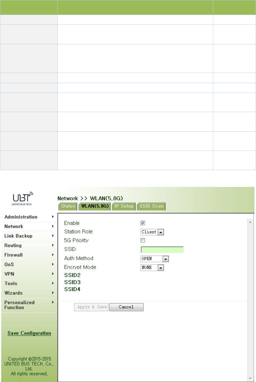
Figure3‐35‐aWLANinterface(5.8G)‐AcessPoint
PagedescriptionisshowninTable3‐15‐a.
Table3‐15‐aAcessPointDescription
ParametersDescriptionDefault
MultipleSSIDClickEnable,enabledreusablecustom3SSIDDisable
SSIDBroadcastOpen"SSIDBroadcast",usercansearchwirelessnetwork
throughSSIDname.Enable
RFType
SixtypesOptional:
802.11g/n,802.11g,802.11n,802.11b,802.11b/g,802.11b/
g/n
802.11g/n
Channel Selectchannel11
SSIDUser‐definedSSIDnameWIFUN1050
AuthenticationFourauthenticationmodesavailable:Open,Shared,
WPA‐PSKandWPA2‐PSKOpen
EncryptionAccordingtothedifferentauthenticationmethods,
supportNONE,WEP40andWEP104NONE
Wireless
BandwidthTwooptions:20MHzand40MHz20MHz
MaximumNumber
ofClients User‐defined(upto128)None

Figure3‐35‐bWLANinterface(5.8G)‐Client
PagedescriptionisshowninTable3‐15‐b.
Table3‐15‐bWLANinterface(5.8G)Description
ParametersDescriptionDefault
5GprioritySelectEnable Disable
SSIDSSIDnametoconnectNone
AuthenticationSSIDauthenticationmethodOpen
EncryptionSSIDencryptionmethodNONE
WhentheWLANissetasClientmode,refertothefollowing3steps:
Step1:select"Network/Cellular"menu,enter"Cellular"page,anddisableCellularfunction.If
therouterdoesnothavecelluarmodule,skipthisstepandgotostep2.
Step2:select"Network/WLAN(5.8G)"menu,enter"WLAN(5.8G)"pageandchoose“Client”to
configurerelatedparametersasshowninFigure3‐35‐b.
Step2:select"Network/WLAN(5.8G)"menu,enter"IPSetup"pagetoconfigureIPparametersas
shownin3.3.3.3IPSetup.
3.3.3.3IPSetup
WLANinterfaceIPaddresssupportmultipleIP,itcanbesetaccordingtodemand,butuptomore
than10.
Fromnavigationpanel,selectNetwork/WLAN(5.8G),enter"IPSetup"page,asshowninFigure
3‐36.
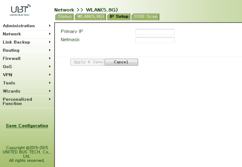
Figure3‐36WLAN(5.8G)IPSetup
3.3.3.4SSIDScan
WLANinterfaceselectsclient(Section3.3.3.2WLANInterface(5.8G)),SSIDscanningfunction
starts.Fromnavigationpanel"Network/WLANinterface(5.8G)"menu,enter"SSIDScan"page,
willdisplayalltheavailableSSIDnames,andthedisplayWIFUN1050canbeconnectedasaclient
state.
3.3.4CaptivePortal
CaptiveportalisWebpagethatusermustvisitandinteractwithbeforegrantedaccesstopublic
accessnetwork.CaptiveportalusuallyoffersfreeWi‐FihotspotservicestoInternetusersin
commercialcenters,airports,hotellobbies,cafesandotherpublicplacestouse.
Fromnavigationpanel"Network/captiveportal"menu,enterthe"captiveportal"page.Asshown
inFigure3‐38.

Figure3‐38CaptivePortal
PagedescriptionisshowninTable3‐16.
Table3‐16CaptivePortalDescription
ParametersDescriptionDefault
LANInterfaceCaptiveportallocalinterfacedotllradio1
WANInterfaceExternalnetworkadaptercellular1
SplashedHomePage PushHometocustomerswifi.go
Authentication
Server
UserauthenticationserverIPaddressforuserlogin
authenticationNone:80
ForceReloginPeriod Forceusertore‐loginNone
SilentUser
AutomaticLogoffUserautomaticlogoffwhennoflow5
ClientFairnessUsedinconjunctionwiththespeedfunctionEnable
SpeedLimitWificlienttrafficrestrictionsNone
KnownUsersAccess
Control
Authenticateduseraccesscontroltwooptionals:
blacklistandwhitelistmode.Blacklist
TrustedMACAddressesList
IDSerialnumberNone
MACAddressMACaddressauthentication‐freeuserNone
Globalwhitelist
IDSerialnumberNone
Domain/IPaddressorIPthatcanbeaccessedwithout
authentication
None
Authenticatedusersblacklist
IDSerialnumberNone
Domain/IPRestrictauthenticateduserstoaccessnetwork,thatis
cannotbeaccessedbyauthenticatedusersto
None
blacklistaddressesorIP
3.3.5DHCPservice
Alongwiththecontinuousexpansionofnetworksizeandcomplicationofnetwork,numberof
computersoftenexceedsdistributableIPaddresses.Meanwhile,inpacewiththeextensive
applicationofportabledevicesandwirelessnetwork,positionofcomputerchangesfrequently,
resultingtothefrequentupgradeofIPaddress,leadingtoamoreandmorecomplicatednetwork
configuration.DHCP(DynamicHostConfigurationProtocol)isaproductforsuchdemands.
DHCPadoptsClient/Servercommunicationmode.ClientsendsconfigurationrequesttoServer
whichfeedsbackcorrespondingconfigurationinformation,includingdistributedIPaddresstothe
ClienttoachievethedynamicconfigurationofIPaddressandotherinformation.
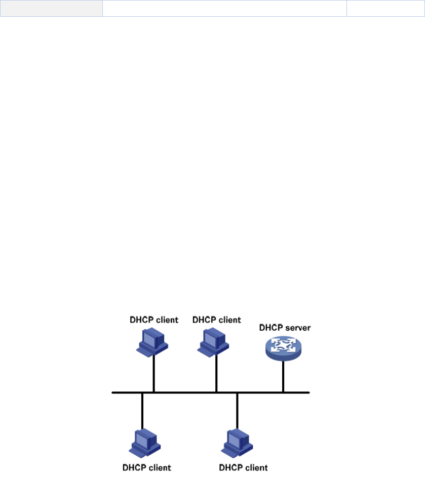
IntypicalapplicationsofDHCP,generallyoneDHCPServerandanumberofClients(PCand
PortableDevices)areincluded,asthefollowingfigureshows:
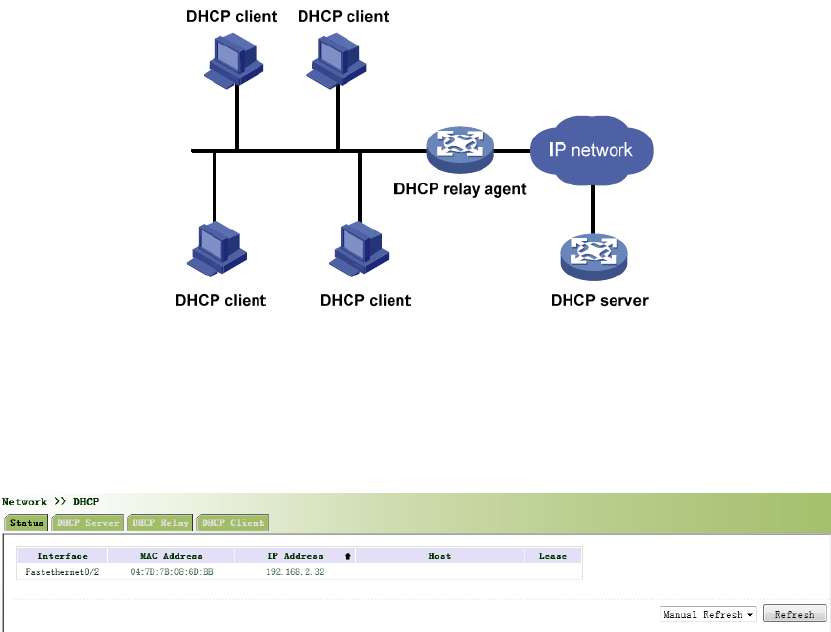
WhenDHCPClientandDHCPServerareindifferentphysicalnetworksegment,Clientcould
communicatewithServerthroughDHCPRelaytoobtainIPaddressandotherconfiguration
information,asthefollowingfigureshows:
3.3.5.1Status
Fromnavigationpanel,selectNetwork/DHCP,thenenter“Status”page,asshowninFigure3‐39.
Figure3‐39DHCPStatus
3.3.5.2DHCPServer
ThedutyofDHCPServeristodistributeIPaddresswhenWorkstationlogsonandensureeach
workstationissuppliedwithdifferentIPaddress.DHCPServerhassimplifiedsomenetwork
managementtasksrequiringmanualoperationsbeforetothelargestextent.
Fromnavigationpanel,selectNetwork>>DHCP,thenenter“DHCPServer”page,asshownin
Figure3‐40.
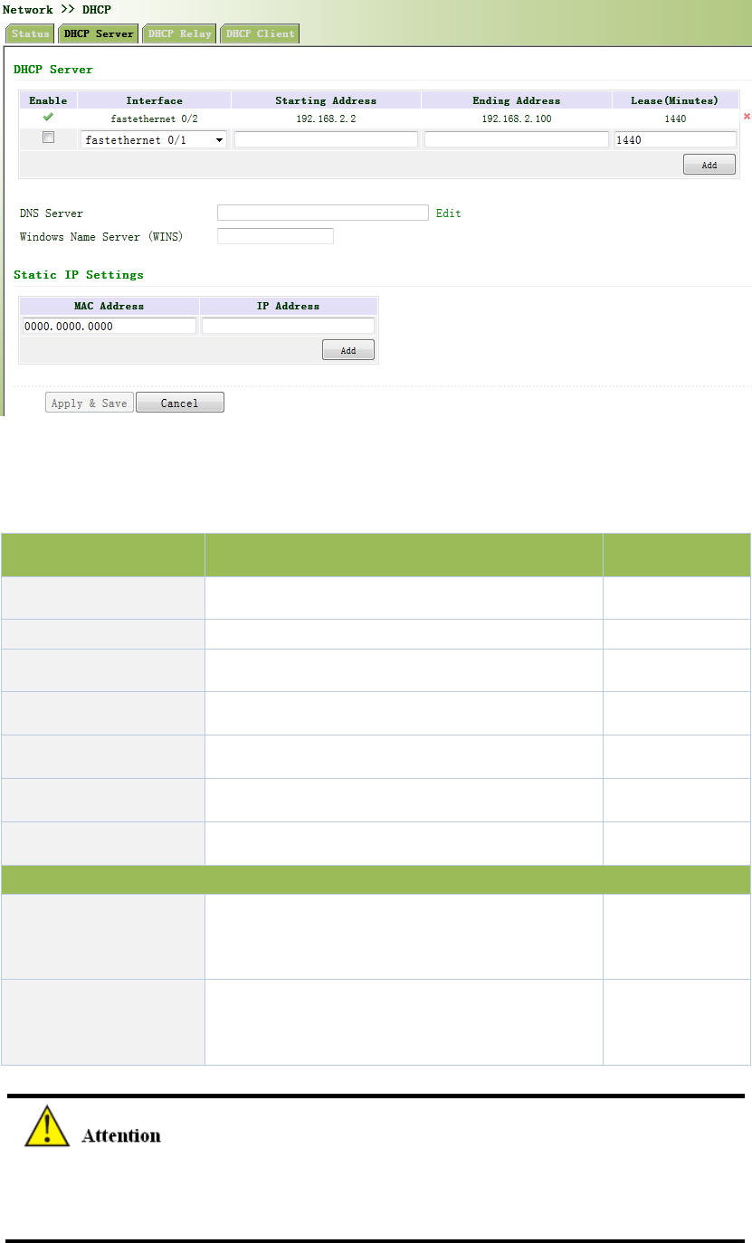
Figure3‐40DHCPServer
PagedescriptionisshowninTable3‐17.
Table3‐17DHCPServerDescription
ParametersDescriptionDefault
EnableOn/OffOff
Interfacedot11radio1dot11radio1
StartingAddressDynamicaldistributionofstartingIPaddressN/A
EndingAddressDynamicaldistributionofendingIPaddressN/A
LeaseDynamicaldistributionofIPvalidity1440
DNSServerOneortwo,orNoneN/A
WINSSetupofWINS,generallyleftblankN/A
StaticIPSetup
MACAddress
SetupastaticspecifiedDHCP’sMACaddress
(differentfromotherMACstoavoidconfliction)
0000.0000.0000
IPAddress
SetupastaticspecifiedIPaddress(withinthe
scopefromstartIPtoendIP)
N/A
IfthehostconnectedwithrouterchoosestoobtainIPaddressautomatically,thensuch
servicemustbeactivated.StaticIPsetupcouldhelpacertainhosttoobtainspecifiedIP
address.
3.3.5.3DHCPRelay
Generally,DHCPdatapacketisunabletobetransmittedthroughrouter.Thatistosay,DHCP
ServerisunabletoprovideDHCPservicesfortwoormoredevicesconnectedwitharouter
remotely.ThroughDHCPrelay,DHCPrequestsandresponsedatapacketcouldgothroughmany
routers(BroadbandRouter).
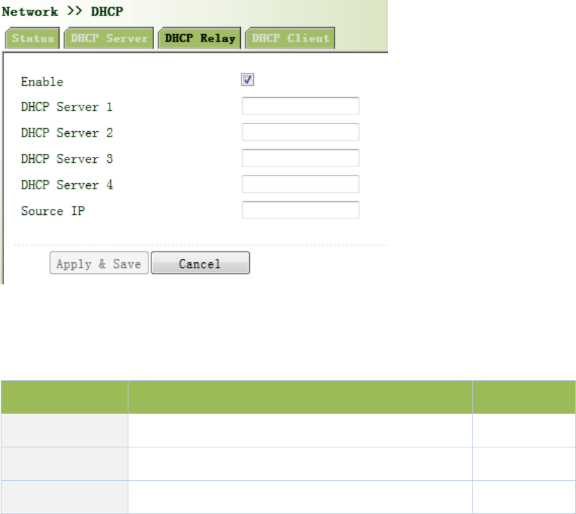
Fromnavigationpanel,selectNetwork/DHCP,thenenter“DHCPRelay”page,asshowninFigure
3‐41.
Figure3‐41DHCPRelay
PagedescriptionisshowninTable3‐18.
Table3‐18DHCPRealyDescription
ParametersDescriptionDefault
EnableOn/OffOff
DHCPSeverSetDHCPserver;upto4serverscanbeconfiguredN/A
SourceIPAddressoftheinterfaceconnectedtotheDHCPserverN/A
3.3.5.4DHCPClient
Fromnavigationpanel,selectNetwork/DHCP,thenenter“DHCPClient”page,byclickingto
enable,chooseSSIDinterface,asshowninFigure3‐42.
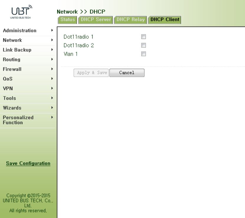
Figure3‐42DHCPClient
3.3.6DNSServices
DNS(DomainNameSystem)isaDDBusedinTCP/IPapplicationprograms,providingswitch
betweendomainnameandIPaddress.ThroughDNS,usercoulddirectlyusesomemeaningful
domainnamewhichcouldbememorizedeasilyandDNSServerinnetworkcouldresolvethe
domainnameintocorrectIPaddress.
Thedevicesupportstoachievefollowingtwofunctionsthroughdomainnameservice
configuration:
DNSServer:fordynamicdomainnameresolution.
DNSrelay:thedevice,asaDNSAgent,relaysDNSrequestandresponsemessagebetween
DNSClientandDNSServertocarryoutdomainnameresolutioninlieuofDNSClient.
3.3.6.1DNSServer
DomainNameServer:DNSstandsforDomainNameSystem.ItisacoreserviceoftheInternet.
AsadistributeddatabasethatcanletthedomainnamesandIPaddressesmappingtoeachother,
itallowspeopletomoreconvenientlyaccesstotheInternetwithouttheneedtomemorizetheIP
stringthatcanbedirectlyreadbythecomputer.
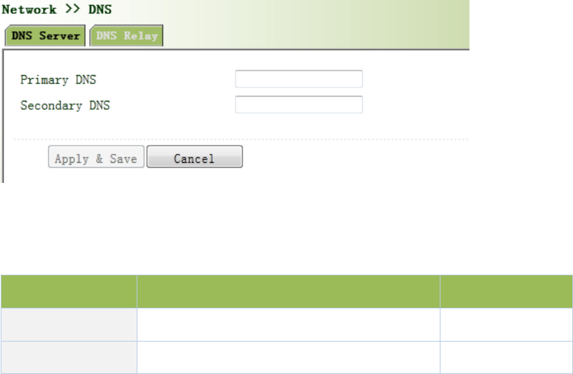
Fromnavigationpanel,selectNetwork/DNS,thenenter“DNSServer”page.Inmanualsetupof
DNSServer,ifitisblank,thendialtoobtainDNS.Generallythisitemisrequiredtobesetwhen
WANportusesstaticIP,asshowninFigure3‐43.
Figure3‐43DNSServer
PagedescriptionisshowninTable3‐19.
Table3‐19DNSServerDescription
ParametersDescriptionDefault
PrimaryDNSUserdefinePrimaryDNSaddress N/A
SecondaryDNSUserdefineSecondaryDNSaddressN/A
3.3.6.2DNSRelay
DNSforwarding:DNSforwardingisopenbydefault.Youcansetthespecified[DomainName<=>
IPAddress]toletIPaddressmatchwiththedomainname,thusallowingaccesstothe
appropriateIPthroughaccessingtothedomainname.
Fromnavigationpanel,selectNetwork/DNS,thenenter“DNSRelay”page,asshownin3‐44.
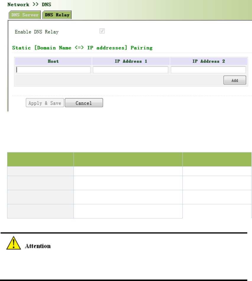
Figure3‐44DNSRelay
PagedescriptionisshowninTable3‐20.
Table3‐20DNSDelayDescription
ParametersDescriptionDefault
EnableDNSRelay On/OffOn
HostDomainNameN/A
IPAddress1SetIPAddress1N/A
IPAddress2SetIPAddress2N/A
OnceDHCPisturnedon,DNSrelaywillbeturnedonasdefaultandcan’tbeturnedoff;toturn
offDNSrely,DHCPServerhastobeclosedfirstly.
3.3.7SMS
SMSpermitsmessage‐basedrebootandmanualdialing.
Fromnavigationpanel,selectNetwork/SMS,thenenter“Basic”page.ConfigurePermitactionto
PhoneNumberandclick<Apply&Save>.Afterthatyoucansend“reboot”commandtorestart
thedeviceor“cellular1pppup/down”toredialordisconnectthedevice,asshowninFigure
3‐45.
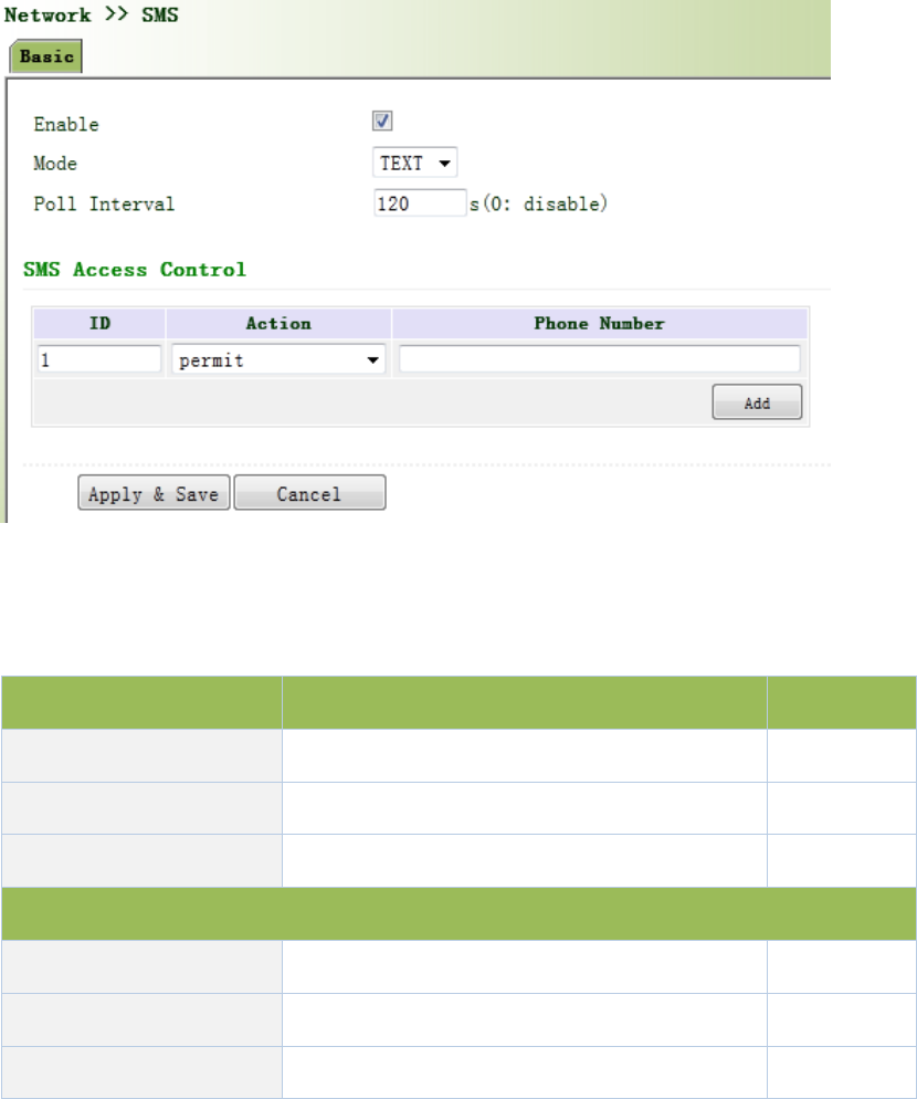
Figure3‐45SMS
PagedescriptionisshowninTable3‐21.
Table3‐21SMSDescription
ParametersDescriptionDefault
EnableOn/OffOff
ModeTEXTandPDUTEXT
PollInterval UserdefinePollInterval 120
SMSAccessControl
IDUserdefineID1
Action Permitandrefuseareavailable Permit
PhoneNumber TrustingphonenumberN/A
3.3.8VLANInterface
VLAN(VirtualLocalAreaNetwork)dividesLANdevicelogicallyintooneandanothernetwork
segment,enableemergingdataexchangetechnologyofvirtualworkgroups.
3.3.8.1VLANConfiguration
Fromnavigationpanel"Network/VLAN"menu,enter"ConfigureVLANParameters"page,click
<Add>buttontoaddtheVLAN,asshowninFigure3‐46.
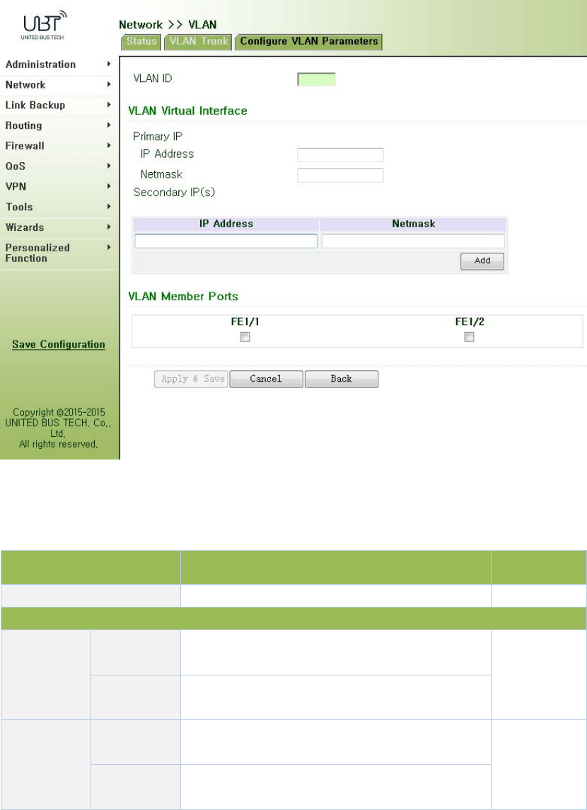
Figure3‐46ConfigureVLANParameters
PagedescriptionisshowninTable3‐22.
Table3‐22ConfigureVLANParametersDescription
ParametersDescriptionDefault
VLANIDVLANID,User‐definedNone
VLANInterface
PrimaryIP
Address
IPaddressUserscanconfigureorchangetheprimaryIP
addressneeded
None
Subnet
Mask
Userscanconfigureorchangethesubnetmaskif
necessary
Secondary
IPAddress
IPaddressInadditiontoprimaryIP,usercanalsoconfigure
10SecondaryIPaddresses
None
Subnet
Mask
Userscanconfigureorchangethesubnetmaskif
necessary
3.3.8.2VLANAggregation
Fromnavigationpanel"Network/VLAN”menu,enter"VLANTrunk"page,setVLANportmodefor
WIFUN1050,themodecanbesettoAccessorTrunk,asshowninFigure3‐47.
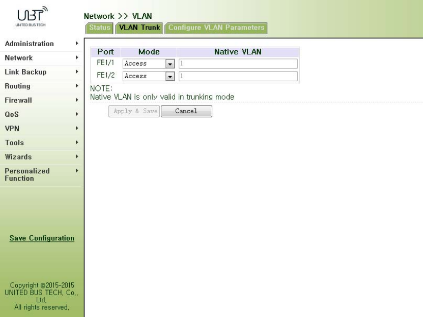
Figure3‐47VLANTrunk
3.3.9ADSLDialup(PPPoE)
PPPoEisPointtoPointProtocoloverEthernet.Usersneedwhilemaintainingtheoriginalaccess,
installaPPPoEclient.ThroughPPPoE,aremoteaccessdevicecanrealizecontrolandaccounting
ofeachaccessuser.
EthernetinterfaceconnectionmodeyouconfigurehereisPPPoE,namelytheinterfaceasPPPoE
client.
Fromnavigationpanel"Network/ADSLDialup(PPPoE)"menu,enter"ADSLDialup(PPPoE)"page,
asshowninFigure3‐48.
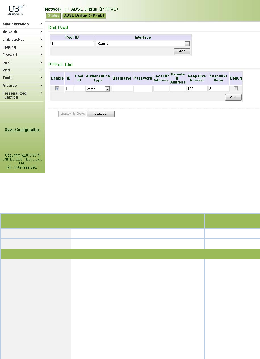
Figure3‐48PPPoE
PagedescriptionisshowninTable3‐23.
Table3‐23PPPoEDescription
ParametersDescriptionDefault
DialPoolUser‐defined,easytorememberandmanageNone
Interface SelectFastethernet0/1orFastethernet0/2Fastethernet0/1
PPPoEList
IDUser‐defined,easytorememberandmanage1
PoolIDDialpoolIndexNone
AuthenticationTypeThreeoptions:Auto,PAP,CHAPAuto
UserNameRelevantparametersprovidedbypeer
operator
None
Password Relevantparametersprovidedbypeer
operator
None
LocalIPAddressAssignedIPaddresstoEthernetinterfaceNone
RemoteIPAddressRemoteIPaddressNone
3.3.10LoopbackInterface
LoopbackisusedtorepresentrouterID,becauseifyouuseactiveinterface,whenactivity
interfaceDOWN,routerIDissubjecttore‐selection,thatwouldcauseOSPFconvergencetime
slow,thusloopbackinterfaceisgenerallyusedasarouterID.
Loopbackinterfaceislogicalandvirtualinterfaceonrouters.Nodefaultrouterloopbackinterface.
Youcancreateanynumberofloopbackinterfacesasneeded.Theseinterfacesonroutertreated
likephysicalinterface:Youcanassignthemaddressinginformation,includingtheirchoiceto
updatethenetworknumberinrouters,oreventerminateIPconnectiononthem.
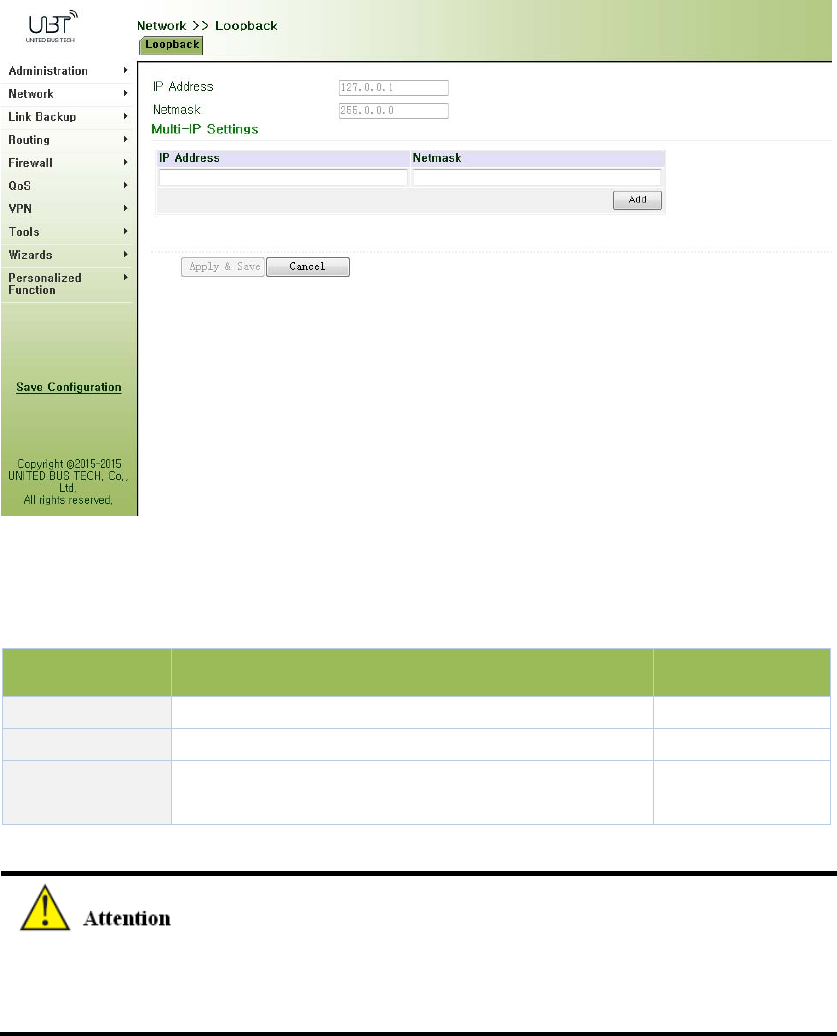
Fromnavigationpanel"Network/LoopbackInterface"menu,enter"loopback"page,shownin
Figure3‐49.
Figure3‐49Loopback
PagedescriptionisshowninTable3‐24.
Table3‐24LoopbackInterfaceDescription
ParametersDescriptionDefault
IPAddressUsercannotchange.127.0.0.1
SubnetMaskUsercannotchange.255.0.0.0
Multi‐IPsettingsInadditiontotheaboveIP,useralsocanbeequipped
withotherIPaddresses
None
SinceloopbackinterfaceisexclusiveofoneIPaddress,subnetmaskisgenerallyrecommended
to255.255.255.255,tosaveresources.
3.3.11DynamicDomainName
DDNSDynamicDomainNameServiceismappinguserdynamicIPaddresstoafixeddomain
nameresolutionservices,whenuserconnecttothenetwork,clientprogramwillpassdynamicIP
addressofthehostthroughinformationtransfertoserverprogramonthehostofservice
providers,theserverprogramisresponsibleforprovidingDNSserviceandrealizingdynamic
domainnameresolution.Thatis,DDNStocapturechangeableIPaddress,thencorresponding
withdomainname,sothatotherInternetuserscancommunicatethroughthedomainname.
Andallfinalcustomerstoremember,istorememberthedynamicdomainnamegivenby
suppliers,withouthavingtopipehowtheyareimplemented.
DDNSfunctionasDDNSclienttools,weneedtoworkwithDDNSserver.Beforeusingthisfeature,
youneedfirsttofindcorrespondingsitessuchas(www.3322.org)andapplyforregistrationofa
domainname.
DDNSservicetypeinclude:DynAccess,QDNS(3322)‐Dynamic,QDNS(3322)‐Static,
DynDNS‐Dynamic,DynDNS‐StaticandNoIP.
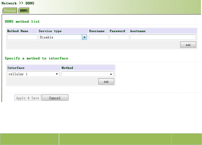
Fromnavigationpanel"Network/DDNS"menu,enter"DDNS"page.Setdynamicbindingdomain.
AsshowninFigure3‐50.
Figure3‐50DynamicDomainName
PagedescriptionisshowninTable3‐25.
Table3‐25DynamicDomainNameDescription
ParametersDescriptionDefault
MethodUser‐definedNone
ServiceTypeSelectdynamicdomainnameserviceprovidersDisable
UserNameApplyregistrationDDNSusernameNone
Password ApplyregistrationDDNSusernameNone
Host ApplyregistrationDDNShostNone
SpecifiedInterface
UpdateMethod
Defineddynamicdomainupdatemethod None
IfIProuterdialobtainaprivateaddress,dynamicDNSfunctionisnotavailable.
3.3.12BridgeInterface
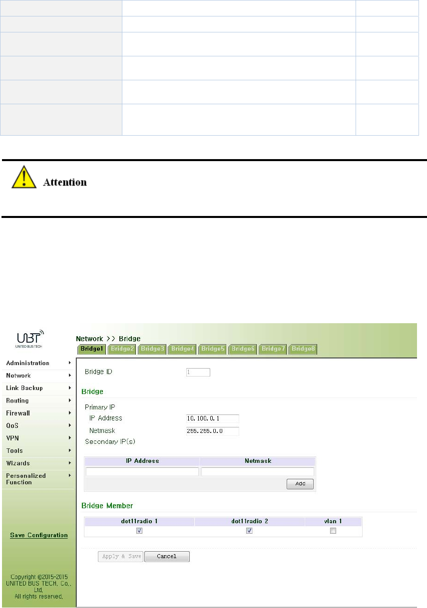
Fromnavigationpanel"Network/Bridge"menu,enter"Bridge1"page,setrelatedparameters,as
showninFigure3‐51.
Figure3‐51Bridge1
PagedescriptionisshowninTable3‐26.
Table3‐26EthernetInterfaceParameterDescription

ParametersDescriptionDefault
BridgeIDBridgenumbercanonlybeassignedto1None
BridgeInterface
IPaddressandsubnetmaskof
primaryaddress
ConfigureorchangetheprimaryIPaddressand
subnetmaskasneeded.None
IPaddressandsubnetmaskof
secondaryaddress
InadditiontoprimaryIPfromoutside,clientsalso
canbeequippedwithsecondaryIPaddressand
subnetmask
None
BridgeMember
ClickenablebridgeinterfaceNone
3.4LinkBackup
3.4.1SLA
BasicConceptsandPrinciples
Undernormalcircumstances,theedgeroutercandetectifthelinklinkedtotheISPisinfault.If
thenetworklinkingtooneISPisinfault,anotherISPwillbeusedtotransmitallthedatastreams.
However,ifthelinkofanISPisnormalandtheinfrastructurefails,theedgerouterwillcontinue
tousethisroute.Then,thedataisnolongerreachable.
Onefeasiblesolutionistousingstaticroutingorpolicy‐basedroutingtofirsttestthereachability
ofimportantdestination.Ifitisunreachable,thestaticroutingwillbedeleted.
ThereachabilitytestcanbeperformedwithInHandSLAtocontinuouslycheckthereachabilityof
ISPandbeassociatedwithstaticrouting.
BasicprinciplesofInHandSLA:1.Objecttrack:Trackthereachabilityofthespecifiedobject.2.
SLAprobe:TheobjecttrackfunctioncanuseInHandSLAtosenddifferenttypesofdetectionsto
theobject.3.Policy‐basedroutingusingroutemappingtable:Itassociatesthetrackresultswith
theroutingprocess.4.Usingstaticroutingandtrackoptions.
SLAConfigurationSteps
Step1:DefineoneormoreSLAoperations(detection).
Step2:DefineoneormoretrackobjectstotrackthestatusofSLAoperation.
Step3:Definemeasuresassociatedwithtrackobjects.
Fromnavigationpanel,selectLinkBackup>>SLA,thenenter“SLA”page,asshowninFigure
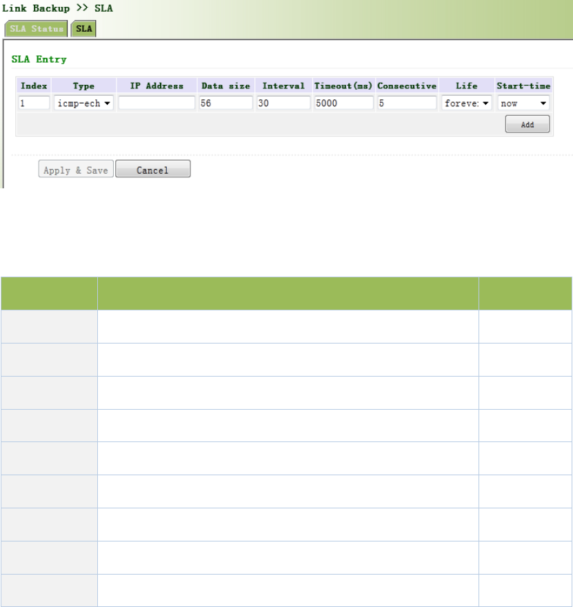
3‐52.
Figure3‐52SLA
PagedescriptionisshowninTable3‐27.
Table3‐27SLADescription
ParametersDescriptionDefault
IndexSLAindexorID1
TypeDetectiontype,defaultisicmp‐echo,theusercannotchange icmp‐echo
IPAddressDetectedIPaddressNone
DataSize Userdefinedatasize 56
Interval Userdefinedetectioninterval 30
Timeout(ms)Userdefine,Timeoutfordetectiontofail5000
ConnecutiveDetectionretries5
LifeDefaultis“forever”,usercannotchange forever
Start‐timeDetectionStart‐time,select“now”orNonenow
3.4.2TrackModule
Trackisdesignedtoachievelinkageconsistingofapplicationmodule,Trackmoduleand
monitoringmodule.Linkagereferstoachievethelinkageamongstdifferentmodulesthroughthe
establishmentoflinkageitems,namely,themonitoringmodulecouldtriggerapplicationmodule
totakeacertainactionthroughTrackmodule.Monitoringmoduleisresponsiblefordetectionof
linkstatus,networkperformanceandnotificationtoapplicationmoduleofdetectionresultsvia
Trackmodule.Oncetheapplicationmodulefindsoutanychangesinnetworkstatus,
correspondingmeasureswillbetakenonatimelybasissoastoavoidinterruptionof
communicationorreductionofservicequality.
Trackmoduleislocatedbetweenapplicationmoduleandmonitoringmodulewithmainfunctions
ofshieldingthedifferencesofdifferentmonitoringmodulesandprovidinguniforminterfacesfor
applicationmodule.
TrackModuleandMonitoringModuleLinkage
Throughconfiguration,thelinkagerelationshipbetweenTrackmoduleandmonitoringmoduleis
established.Monitoringmoduleisresponsiblefordetectionoflinkstatus,networkperformance
andnotificationtoapplicationmoduleofdetectionresultsviaTrackmodulesoastocarryout
timelychangeofthestatusofTrackitem:
Successfuldetection,correspondingtrackitemisPositive
Faileddetection,correspondingtrackitemisNegative
TrackModuleandApplicationModuleLinkage
Throughconfiguration,thelinkagerelationshipbetweenTrackmoduleandapplicationmoduleis
established.Incaseofanychangesintrackitem,anotificationrequiringcorrespondent
treatmentwillbesenttoapplicationmodule.
Currently,applicationmoduleswhichcouldachievelinkagewithtrackmoduleinclude:VRRP,
staticrouting,strategy‐basedroutingandinterfacebackup.
Undercertaincircumstances,onceanychangesinTrackitemarefounded,ifatimelynotification
issenttoapplicationmodule,thencommunicationmaybeinterruptedduetorouting’sfailurein
timelyrestorationandotherreasons.Forexample,MasterrouterinVRRPbackupgroupcould
monitorthestatusofupstreaminterfacethroughTrack.Incaseofanyfaultinupstreaminterface,
MasterrouterwillbenotifiedtoreduceprioritysothatBackuproutermayascendtothenew
Mastertoberesponsibleforrelayofmessage.Onceupstreaminterfaceisrecovered,solongas
TrackimmediatelysendsamessagetooriginalMasterroutertorecoverpriority,thentherouter
willtakeoverthetaskofmessagerelay.Atthattime,messagerelayfailuremayoccursincethe
routerhasnotrestoredtotheupstreamrouter.Undersuchcircumstances,usertoconfigurethat
onceanychangestakeplaceinTrackitem,delaysaperiodoftimetonotifytheapplication
module.
Fromnavigationpanel,selectLinkBackup/Track,thenenter“Track”page,asshownFigure3‐53.
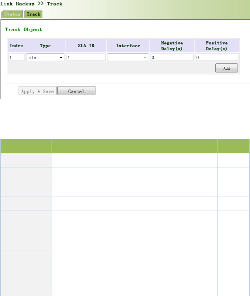
Figure3‐53TrackM
PagedescriptionisshowninTable3‐28.
Table3‐28TrackDescription
ParametersDescriptionDefault
Index TrackindexorID1
TypeDefault“sla”,Usercannotchangesla
SLAIDDefinedSLAIndexorIDNone
InterfaceDetectinterface’sup/downstatecellular1
NegativeDelay
(m)
Incaseofnegativestatus,switchingcanbedelayedbasedon
thesettime(0representsimmediateswitching),ratherthan
immediateswitching.
0
PositiveDelay
(m)
Incaseoffailurerecovery,switchingcanbedelayedbasedon
thesettime(0representsimmediateswitching),ratherthan
immediateswitching.
0
3.4.3VRRP
Defaultrouteprovidesconvenienceforuser’sconfigurationoperationsbutalsoimposeshigh
requirementsonstabilityofthedefaultgatewaydevice.Allhostsinthesamenetworksegment
aresetupwithanidenticaldefaultroutewithgatewaybeingthenexthopingeneral.Whenfault
occursongateway,allhostswiththegatewaybeingdefaultrouteinthenetworksegmentcan’t
communicatewithexternalnetwork.
Increasingexitgatewayisacommonmethodforimprovingsystemreliability.Then,theproblem
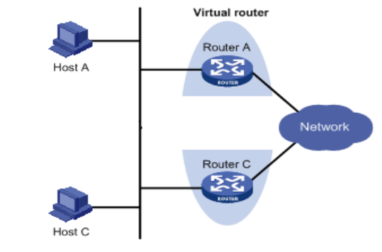
tobesolvedishowtoselectrouteamongmultipleexits.VRRP(VirtualRouterRedundancy
Protocol)addsasetofroutersthatcanundertakegatewayfunctionintoabackupgrouptoforma
virtualrouter.TheelectionmechanismofVRRPwilldecidewhichroutertoundertakethe
forwardingtaskandthehostinLANisonlyrequiredtoconfigurethedefaultgatewayforthe
virtualrouter.
VRRPwillbringtogetherasetofroutersinLAN.Itconsistsofmultipleroutersandissimilartoa
virtualrouterinrespectoffunction.Accordingtothevlaninterfaceipofdifferentnetwork
segments,itcanbevirtualizedintomultiplevirtualrouters.EachvirtualrouterhasanIDnumber
andupto255canbevirtualized.
VRRPhasthefollowingcharacteristics:
VirtualrouterhasanIPaddress,knownastheVirtualIPaddress.ForthehostinLAN,it
isonlyrequiredtoknowtheIPaddressofvirtualrouter,andsetitastheaddressofthe
nexthopofthedefaultroute.
Hostinthenetworkcommunicateswiththeexternalnetworkthroughthisvirtual
router.
1routerwillbeselectedfromthesetofroutersbasedonprioritytoundertakethe
gatewayfunction.Otherrouterswillbeusedasbackuprouterstoperformthedutiesof
gatewayforthegatewayrouterincaseoffaultofgatewayrouter,thustoguarantee
uninterruptedcommunicationbetweenthehostandexternalnetwork
VRRPNetworkingScheme:
AsshowninFigureabove,RouterAandRouterCcomposeavirtualrouter.Thisvirtualrouterhas
itsownIPaddress.ThehostinLANwillsetthevirtualrouterasthedefaultgateway.RouterAor
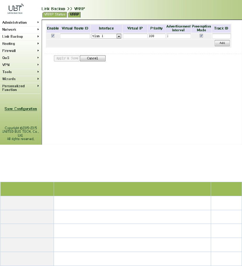
RouterC,theonewiththehighestpriority,willbeusedasthegatewayroutertoundertakethe
functionofgateway.AnotherrouterwillbeusedasaBackuprouter.
MonitorinterfacefunctionofVRRPbetterexpandsbackupfunction:thebackupfunctioncanbe
offeredwheninterfaceofacertainrouterhasfaultorotherinterfacesoftherouterare
unavailable.
WheninterfaceconnectedwiththeuplinkisatthestateofDownorRemoved,therouteractively
reducesitsprioritysothatthepriorityofotherroutersinthebackupgroupishigherandthusthe
routerwithhighestprioritybecomesthegatewayforthetransmissiontask.
Fromnavigationpanel,selectLinkBackup/VRRP,thenenter“VRRP”page,asshowninFigure
3‐54.
Figure3‐54VRRP
PagedescriptionisshowninTable3‐29.
Table3‐29VRRPDescription
ParametersDescriptionDefault
EnableEnable/DisableEnable
VirtualRouteIDUserdefineVirtualRouteIDNone
InterfaceConfiguretheinterfaceofVirtualRoutevlan1
VirtualIPAddressConfiguretheIPaddressofVirtualRouteNone
PriorityTheVRRPpriorityrangeis0‐255(alargernumberindicates100

ahigherpriority).Therouterwithhigherprioritywillbe
morelikelytobecomethegatewayrouter.
Advertisement
Interval
Heartbeatpackagetransmissiontimeintervalbetween
routersinthevirtualipgroup
1
PreemptionMode
Iftherouterworksinthepreemptivemode,onceitfinds
thatitsownpriorityishigherthanthatofthecurrent
gatewayrouter,itwillsendVRRPnotificationpackage,
resultinginre‐electionofgatewayrouterandeventually
replacingtheoriginalgatewayrouter.Accordingly,the
originalgatewayrouterwillbecomeaBackuprouter.
Enable
TrackIDTraceDetection,selectthedefinedTrackindexorID None
3.4.4InterfaceBackup
Interfacebackupreferstobackuprelationshipformedbetweenappointedinterfacesinthesame
equipment.Whenservicetransmissioncan’tbecarriedoutnormallyduetofaultofacertain
interfaceorlackofbandwidth,rateofflowcanbeswitchedtobackupinterfacequicklyandthe
backupinterfacewillcarryoutservicetransmissionandsharenetworkflowsoastoraise
reliabilityofcommunicationofdataequipment.
Whenlinkstateofmaininterfaceisswitchedfromuptodown,systemwillwaitforpresetdelay
firstinsteadofswitchingtolinkofbackupinterfaceimmediately.Onlyifthestateofmain
interfacestillkeepsdownafterthedelay,systemwillswitchtolinkofbackupinterface.
Otherwise,systemwillnotswitch.
Afterlinkstateofmaininterfaceisswitchedfromdowntoup,systemwillwaitforpresetdelay
firstinsteadofswitchingbacktomaininterfaceimmediately.Onlyifstateofmaininterfacestill
keepsupafterthedelay,systemwillswitchbacktomaininterface.Otherwise,systemwillnot
switch.
Fromnavigationpanel,selectLinkBackup/InterfaceBackup,thenenter“InterfaceBackup”page,
asshowninFigure3‐55.

Figure3‐55InterfaceBackup
PagedescriptionisshowninTable3‐30.
Table3‐30InterfaceBackupDescription
ParametersDescriptionDefault
PrimaryInterfaceTheinterfacebeingusedcellular1
BackupInterfaceInterfacetobeswitchedcellular1
Start‐upDelaySethowlongtowaitforthestart‐uptrackingdetection
policytotakeeffect
60
UpDelay
Whentheprimaryinterfaceswitchesfromfailed
detectiontosuccessfuldetection,switchingcanbe
delayedbasedonthesettime(0representsimmediate
switching),ratherthanimmediateswitching.
0
DownDelay
Whentheprimaryinterfaceswitchesfromsuccessful
detectiontofaileddetection,switchingcanbedelayed
basedonthesettime(0representsimmediate
switching),ratherthanimmediateswitching.
0
TrackIDTraceDetection,selectthedefinedTrackindexorIDNone
3.5Routing
3.5.1StaticRoute
Staticroutingisaspecialroutingthatrequiresyourmanualsetting.Aftersettingstaticrouting,
thepackageforthespecifieddestinationwillbeforwardedaccordingtothepathdesignatedby
you.Inthenetworkwithrelativelysimplenetworkingstructure,itisrequiredtosetstaticrouting

toachievenetworkinterworking.Propersettingandusestaticroutingcanimprovethe
performanceofnetworkandcanguaranteebandwidthforimportantnetworkapplications.
Disadvantagesofstaticrouting:Itcannotautomaticallyadapttothechangesinthenetwork
topology.Thenetworkfailureorchangesintopologymaycausetherouteunreachableand
networkinterrupted.Then,youarerequiredtomanuallymodifythesettingofstaticrouting.
StaticRoutingperformsdifferentpurposesindifferentnetworkenvironments.
Whenthenetworkstructureiscomparativelysimple,thenetworkcanworknormally
onlywithStaticRouting.
Whileincomplexnetworkenvironment,StaticRoutingcanimprovetheperformanceof
networkandensurebandwidthforimportantapplication.
StaticRoutingcanbeusedinVPNexamples,mainlyforthemanagementofVPNroute.
3.5.1.1RoutingStatus
Fromnavigationpanel,selectRouting/StaticRouting,thenenter“RouteTable”page,asshownin
Figure3‐56.
Figure3‐56RoutingStatus
3.5.1.2StaticRouting
Fromnavigationpanel,selectRouting/StaticRouting,thenenter“StaticRouting,”page.
Add/deleteadditionalRouterstaticrouting.Normallyusersdonnotneedtoconfigurethisitem,
asshownin3‐57.

Figure3‐57StaticRouting
PagedescriptionisshowninTable3‐31.
Table3‐31StaticRoutingDescription
ParametersDescriptionDefault
Destinationaddress EnterthedestinationIPaddressneedtobereachedNone
SubnetMaskEnterthesubnetmaskofdestinationaddressneedtobe
reached
None
InterfaceTheinterfacethroughwhichthedatareachesthe
destinationaddress
None
GatewayIPaddressofthenextroutertobepassedbybeforethe
inputdatareachesthedestinationaddress
None
DistancePriority,smallervaluecontributestohigherpriorityNone
TrackIDSelectthedefinedTrackindexorIDNone
3.5.2DynamicRouting
Theroutingtableentryondynamicrouterisobtainedinaccordancewithcertainalgorithm
optimizationthroughtheinformationexchangebetweentheconnectedrouters,whilethe
routinginformationiscontinuouslyupdatingincertaintimeslotsoastoadapttothe
continuouslychangingnetworkandobtaintheoptimizedpathfindingeffectsatanytime.
InordertoachieveefficientpathfindingofIPpacket,IETFhasdevelopedavarietyof
pathfindingprotocols,includingOpenShortestPathFirst(OSPF)andRoutingInformation
Protocol(RIP)forAutonomousSystem(AS)interiorgatewayprotocol.Theso‐calledautonomous
systemreferstothecollectionofhosts,routersandothernetworkdevicesunderthe

managementofthesameentity(e.g.schools,businesses,orISP)
3.5.2.1RoutingStatus
Fromnavigationpanel,selectRouting/DynamicRouting,thenenter“RouteTable”page,asshown
inFigure3‐58.
Figure3‐58RoutingStatus
3.5.2.2RIP
RIP(RoutingInformationProtocol)isarelativelysimpleinteriorgatewayprotocol(IGP),mainly
usedforsmallernetworks.ThecomplexenvironmentsandlargenetworksgeneraldonotuseRIP.
RIPusesHopCounttomeasurethedistancetothedestinationaddressanditiscalled
RoutingCost.InRIP,thehopcountfromtheroutertoitsdirectlyconnectednetworkis0andthe
hopcountofnetworktobereachedthrougharouteris1andsoon.Inordertolimitthe
convergencetime,thespecifiedRoutingCostofRIPisanintegerintherangeof0~15andhop
countlargerthanorequalto16isdefinedasinfinity,whichmeansthatthedestinationnetwork
orhostisunreachable.Becauseofthislimitation,theRIPisnotsuitableforlarge‐scalenetworks.
Toimproveperformanceandpreventroutingloops,RIPsupportssplithorizonfunction.RIPalso
introducesroutingobtainedbyotherroutingprotocols.
ItisspecifiedinRFC1058RIPthatRIPiscontrolledbythreetimers,i.e.Periodupdate,Timeout
andGarbage‐Collection:
EachrouterthatrunsRIPmanagesaroutingdatabase,whichcontainsroutingentriestoreachall
reachabledestinations.Theroutingentriescontainthefollowinginformation:
Destinationaddress:IPaddressofhostornetwork.
Addressofnexthop:IPaddressofinterfaceoftherouter’sadjacentroutertobepassedby
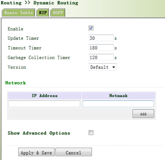
onthewaytoreachthedestination.
Outputinterface:Theoutputinterfacefortheroutertoforwardpackage.
RoutingCost:Costfortheroutertoreachthedestination.
Routingtime:Thetimefromthelastupdateofrouterentrytothepresent.Eachtimethe
routerentryisupdated,theroutingtimewillberesetto0.
Fromnavigationpanel,selectRouting>>DynamicRouting,thenenter“RIP”page,asshownFigure
3‐59‐1.
Figure3‐59‐1RIP
AdvancedOptionsareshowninFigure3‐59‐2.

Figure3‐59‐2RIP
PagedescriptionisshowninTable3‐32.
Table3‐32RIPDescription
ParametersDescriptionDefault
EnableEnable/DisableDisable
UpdatetimerItdefinestheintervaltosendroutingupdates30
Timeouttimer
Itdefinestheroutingagingtime.Ifnoupdatepackageon
aroutingisreceivedwithintheagingtime,therouting’s
RoutingCostintheroutingtablewillbesetto16.
180
ClearTimer
ItdefinesthetimefromthetimewhentheRoutingCost
ofaroutingbecomes16tothetimewhenitisdeleted
fromtheroutingtable.Inthetimeof
Garbage‐Collection,RIPuses16astheRoutingCostfor
sendingupdatesoftherouting.Incaseoftimeoutof
Garbage‐Collectionandtheroutingstillhasnotbeen
updated,theroutingwillbecompletelyremovedfrom
theroutingtable.
120
NetworkThefirstIPaddressandsubnetmaskofthesegmentNone

AdvancedOptions
DefaultPostClickEnable,thedefaultinformationwillenable
publishingDisable
DefaultMetricDefaultcostofroutertodestination1
Redirectdirectroute
Direct,Static,andOSProuteagreementintroducedto
RIProuteagreement
Disable
RedirectStatic
RoutEDisable
RedirectOSPRoutEDisable
AdvancedOptions‐Distance/MetricManagement
DistanceSetRIProutingadministrativedistance,priority,the
smallervalue,thepriority 120
IPaddressNetworknumberisthefirstIPaddressinnetwork
segmentNone
SubnetMaskSubnetmask,networknumberissubnetmaskofthefirst
IPaddressinnetworksegmentNone
AccessListApplicationoftheACLIDNone
Redirectrouting
metricRewritedefaultcostfromroutetothedestination None
Ingress/egress
filteringpolicySetredirectionroutefilteringpolicy(in/out)in
Interface SetInterfacerewritingtorouteNone
AccessListApplicationoftheACLIDNone
AdvancedOptions‐RouteFilteringPolicy
PolicyTypeSelectthetypeofpolicytoimplementAccess‐list
PolicynameCustompolicynameNone
Ingress/egress
filteringpolicySelectpolicyappliedintheoutboundorinboundin
Interface SelectroutefilteringpolicyenforcementInterfaceNone
SendfiltrationAfterenabling,onlyRIPpacketsendtothedefault
routinginterface.Disable
AdvancedOptions‐Interface
PassiveInterfaceAfterenabling,onlyreceiveRIPpacket,nosendDisable
RIPsendversion SelectSendRIPpacketversionDefault
RIPReceiveversionChoosereceiveRIPpacketversionDefault
Horizontalsplit/
toxicityFlipSelectenablesplithorizonorpoisonreversefunctionNone
AuthenticationSelecttheinterfaceauthenticationmodeNone
Key FillinthecorrespondingkeyNone
AdvancedOptions‐Neighbor
IPaddressNeighborIPaddressNone
3.5.2.3OSPF
OpenShortestPathFirst(OSPF)isalinkstatusbasedinteriorgatewayprotocoldevelopedbyIETF.
RouterID
IfarouterwantstoruntheOSPFprotocol,thereshouldbeaRouterID.RouterIDcanbe
manuallyconfigured.IfnoRouterIDisconfigured,thesystemwillautomaticallyselectoneIP
addressofinterfaceastheRouterID.
Theselectionorderisasfollows:
IfaLoopbackinterfaceaddressisconfigured,thenthelastconfiguredIPaddressof
LoopbackinterfacewillbeusedastheRouterID;
IfnoLoopBackinterfaceaddressisconfigured,choosetheinterfacewiththebiggestIP
adressfromotherinterfacesastheRouterID.
NeighborandNeighboring
Afterthestart‐upofOSPFrouter,itwillsendoutHellopacketsthroughtheOSPFinterface.Upon
receiptofHellopacket,OSPFrouterwillchecktheparametersdefinedinthepacket.Ifbothare
consistent,aneighborrelationshipwillbeformed.Notallbothsidesinneighborrelationshipcan
formtheadjacencyrelationship.Itisdeterminedbasedonthenetworktype.Onlywhenboth
sidessuccessfullyexchangeDDpacketsandLSDBsynchronizationisachieved,theadjacencyin
thetruesensecanbeformed.LSAdescribethenetworktopologyaroundarouter,LSDBdescribe
entirenetworktopology.
Fromnavigationpanel,selectRouting/DynamicRouting,thenenter“OSPF”page,asshownin
Figure3‐60.
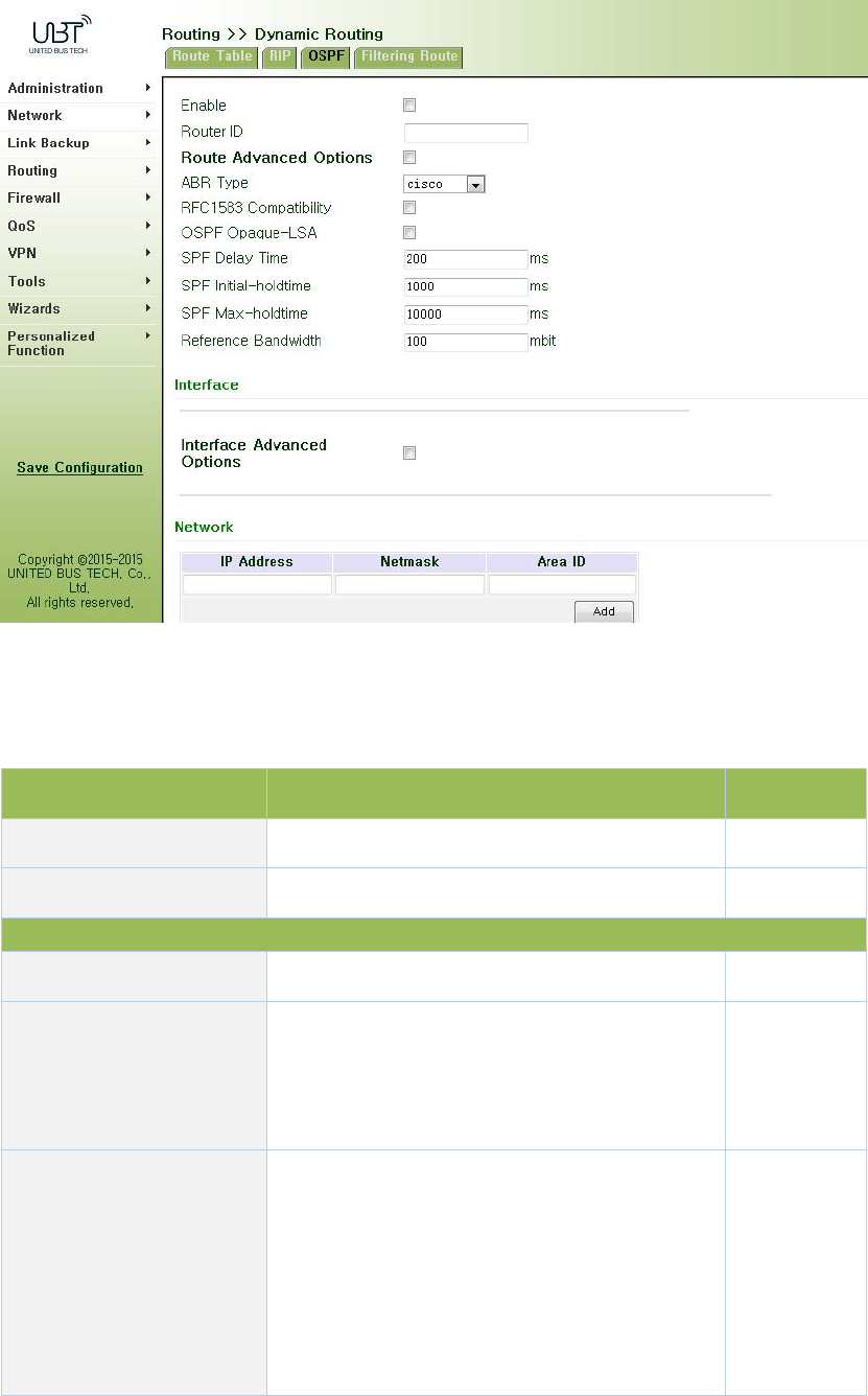
Figure3‐60OSPF
PagedescriptionisshowninTable3‐33.
Table3‐33OSPFDescription
ParametersDescriptionDefault
EnableEnable/DisableDisable
RouterIDRouterIDoftheoriginatingtheLSANone
Interface
Interface Theinterface None
HelloInterval
SendintervalofHellopacket.IfthetheHello
timebetweentwoadjacentroutersisdifferent,
youcannotestablishaneighborrelationship.
10
DeadInterval
DeadTime.IfnoHellopacketisreceivedfrom
theneighbors,theneighborisconsideredfailed.
Ifdeadtimesoftwoadjacentroutersare
different,theneighborrelationshipcannotbe
established.
40

RetransmitInterval
WhentherouternotifiesanLSAtoitsneighbor,
itisrequiredtomakeacknowledgement.Ifno
acknowledgementpacketisreceivedwithinthe
retransmissioninterval,thisLSAwillbe
retransmittedtotheneighbor.
5
LSAtransmissiondelay
timer
OSPFpacketalsoneedtospendtimewhen
travelingonlinks,soLSAagingtime(age)before
transferringtoaddadelaytime,inthe
low‐speedlinksrequireconsiderationof
configuration.
1
Interface‐InterfaceAdvancedOptions
InterfaceNameConfigureOSPFinterfaceparametersNone
PassiveInterfaceAfterenabling,onlyreceiveRIPpacket,nosendDisable
InterfaceCostBydefault,aninterfacecomputesitscost
accordingtothebandwidth10
ProtocolPriorityConfigureOSPFrouterinterfacepriority10
Network
IPAddress IPAddressoflocalnetwork None
SubnetMask SubnetMaskofIPAddressoflocalnetworkNone
AreaIDAreaIDofrouterwhichoriginatingLSA None
3.5.2.4FilteringRoute
Clicknavigationpanel“Routing/DynamicRouting”menu,enter“FilteringRoute”interface,as
showninFigure3‐61.
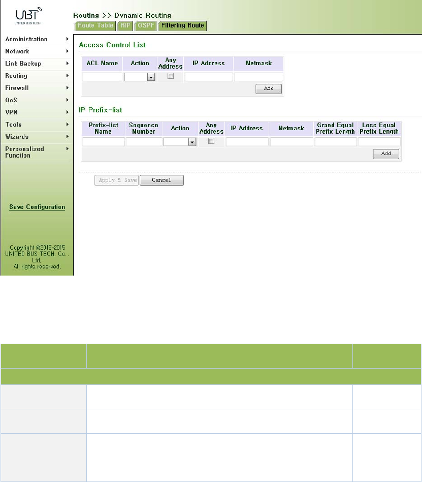
Figure3‐61FilteringRoute
PagedescriptionisshowninTable3‐34.
Table3‐34FilteringRouteDescription
ParameterDescriptionDefault
AccessControlList
AccesslistUserdefined None
ActionPermitanddenyPermit
AnyAddress Anyaddressafterclicking,nomatchingIPaddressand
subnetmaskagain
Disable
3.5.3MulticastRouting
Multicastroutingsetsupanacyclicdatatransmissionroutefromdatasourceendtomultiple
receivingends,whichreferstotheestablishmentofamulticastdistributiontree.Themulticast
routingprotocolisusedforestablishingandmaintainingthemulticastroutingandforrelaying
multicastdatapacketcorrectlyandefficiently.
3.5.3.1BasicSettings
Thebasicismainlytodefinethesourceofmulticastrouting.
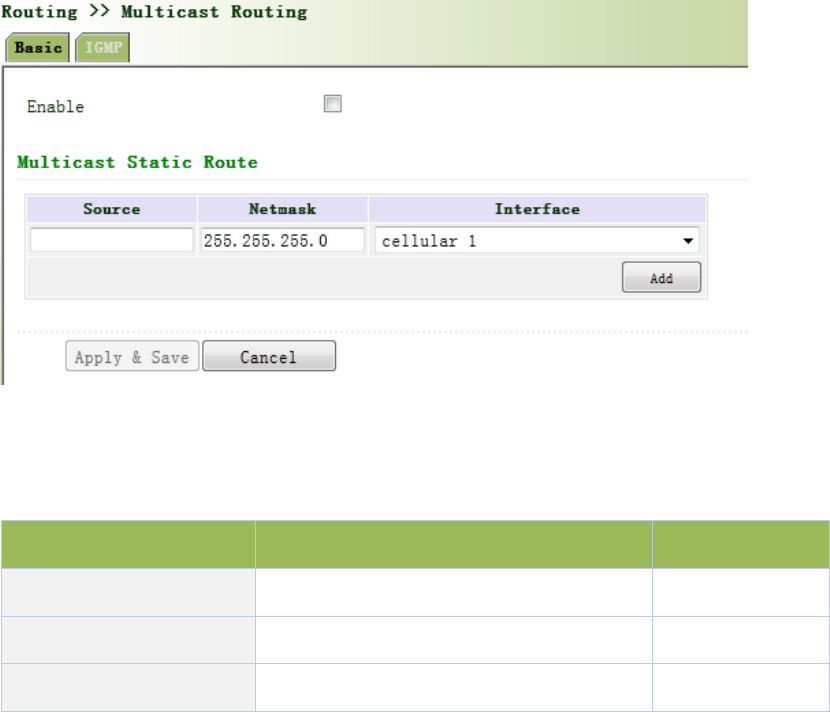
Fromnavigationpanel,selectRouting/MulticastRouting,thenenter“Basic”page,asshownin
Figure3‐62.
Figure3‐62BasicSettings
PagedescriptionisshowninTable3‐35.
Table3‐35BasicSettingsDescription
ParametersDescriptionDefault
EnableOpen/CloseClose
SourceIPAddressofSource None
Netmask NetmaskofSource 255.255.255.0
3.5.3.2IGMP
IGMP,beingamulticastprotocolinInternetprotocolfamily,whichisusedforIPhosttoreportits
constitutiontoanydirectlyadjacentrouter,definesthewayformulticastcommunicationofhosts
amongstdifferentnetworksegmentswithpreconditionthattherouteritselfsupportsmulticast
andisusedforsettingandmaintainingtherelationshipbetweenmulticastmembersbetweenIP
hostandthedirectlyadjacentmulticastrouting.IGMPdefinesthewayformaintenanceof
memberinformationbetweenhostandmulticastroutinginanetworksegment.
Inthemulticastcommunicationmodel,sender,withoutpayingattentiontotheposition
informationofreceiver,onlyneedstosenddatatotheappointeddestinationaddress,whilethe
informationaboutreceiverwillbecollectedandmaintainedbynetworkfacility.IGMPissucha
signalingmechanismforahostusedinthenetworksegmentofreceivertotherouter.IGMP
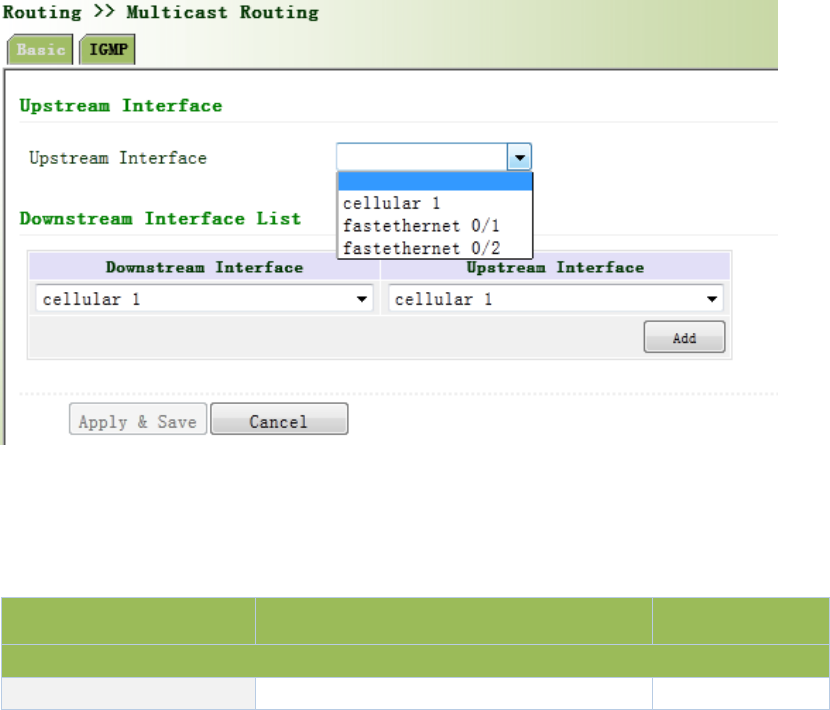
informstheroutertheinformationaboutmembersandtherouterwillacquirewhetherthe
multicastmemberexistsonthesubnetconnectedwiththerouterviaIGMP.
Functionofmulticastroutingprotocol:
Discoveringupstreaminterfaceandinterfaceclosesttothesourceforthereasonthat
multicastroutingprotocolonlycarestheshortestroutetothesource.
Decidingtherealdownstreaminterfacevia(S,G).Amulticasttreewillbefinishedafterall
routersacquiretheirupstreamanddownstreaminterfaceswithrootbeingrouterdirectly
connectedwiththesourcehostandbranchesbeingroutersdirectlyconnectedviasubnet
withmemberdiscoveredbyIGMP.
Managingmulticasttree.Themessagecanbetransferredoncetheaddressofnexthopcan
beacquiredbyunicastrouting,whilemulticastreferstorelaymessagegeneratedbysource
toagroup.
Fromnavigationpanel,selectRouting/MulticastRouting,thenenter“IGMP”page,asshownin
Figure3‐63.
Figure3‐63IGMP
PagedescriptionisshowninTable3‐36.
Table3‐36IGMPDescription
ParametersDescriptionDefault
UplinkInterface
UplinkInterfacelinktouppernetworkdeviceinterfaceNone
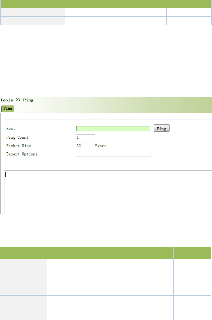
DownlinkInterface
DownlinkInterfacelinktoterminalequipmentinterfacecellular1
UplinkInterfacelinktouppernetworkdeviceinterfacecellular1
3.6Tools
3.6.1PING
HelptoPINGinternetthroughroute.
Fromnavigationpanel,selectTools/Ping,thenenter“Ping”page,asshowninFigure3‐64.
Figure3‐64PING
PagedescriptionisshowninTable3‐37.
Table3‐37PINGDescription
ParametersDescriptionDefault
HostItrequiresthedestinationhostaddressofPING
detection
192.168.2.1
PingCountSetPingdetectioncount 4
PacketSize Setpacketsizeofpingdetection 32bytes
ExpertOptionsAdvancedparametersofpingcanbeusedNone
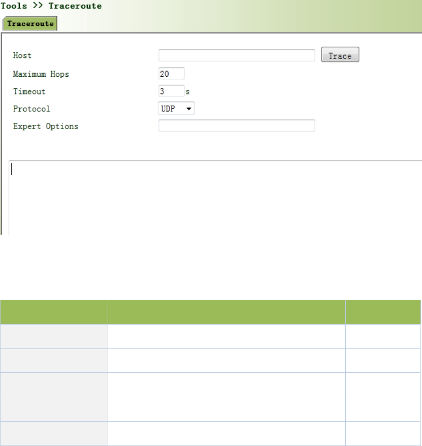
3.6.2RoutingDetection
Itisusedtodetectnetworkroutingfailure.
Fromnavigationpanel,selectTools/Traceroute,thenenter“Traceroute”page,asshowninFigure
3‐65.
Figure3‐65Traceroute
PagedescriptionisshowninTable3‐38.
Table3‐38TracerouteDescription
ParametersDescriptionDefault
HostHostaddressneedstodetect 192.168.2.1
MaxiumHopsSetthemaxiumhopsofroutingdetection 20
TimeoutSettimeoutofroutingdetection3secs
ProtocolSelectICMP/UDPUDP
ExpertOptions AdvancedparametersofpingcanbeusedNone
3.6.3LinkSpeedTest
Throughuploadanddownloadfiles,linkspeedcanbetested.
Fromnavigationpanel,selectTools/LinkSpeedTest ,thenenter“LinkSpeedTest ” page,asshown
inFigure3‐66.
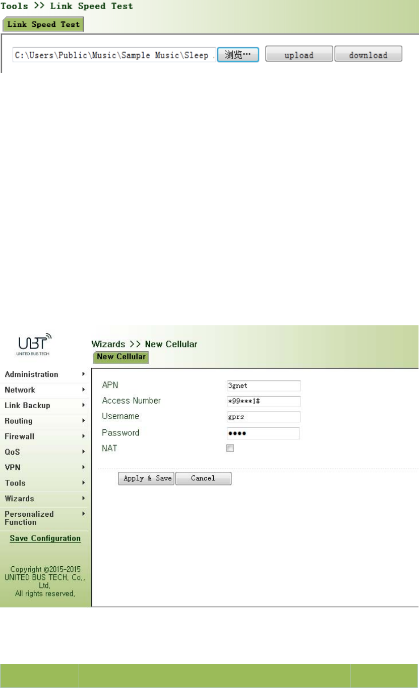
Figure3‐66LinkSpeedTest
3.7InstallationGuide
Simplifygeneralconfiguration,wheretherouterwithfast,simple,basicconfiguration,
configurationresultcannotbedisplayedhere,butviewitwhenfinishedinaspecific
correspondingconfigurationsetting.
3.7.1NewDial
Fromnavigationpanel"Wizards/NewCellular"menu,enter"NewCellular"page,asshownin
Figure3‐67.
Figure3‐67NewCellular
PagedescriptionisshowninTable3‐39.
Table3‐39NewCellularDescription
ParametersDescriptionDefault

APNSelectNewWANInterface3gnet
AccessnumberMobileoperatorprovidedial‐upparameters(pleasechoose
accordingtothelocaloperator)*99***1#
UsernameMobileoperatorprovidedial‐upparameters(pleasechoose
accordingtothelocaloperator)gprs
passwordMobileoperatorprovidedial‐upparameters(pleasechoose
accordingtothelocaloperator)
●●●●
Network
Address
Translation
ClickEnable,putprivateIPaddressconvertedintoapublicIP
addressDisable
3.7.2NewIPSecTunnel
Fromnavigationpanel"Wizards/NewIPSecTunnel"menu,enter"NewIPSecTunnel"page,as
showninFigure3‐68.
Table3‐68NewIPSecTunnel
PagedescriptionisshowninTable3‐40.
Table3‐40NewIPSecTunnelDescription
ParametersDescriptionDefault
Basic
TunnelNo.SetTunnelNo.1
InterfaceNameSelectInterfaceNamecellular1
PeerAddressSetVPNpeerIPNone
NegotiationModeOptionalmainmode,aggressivemode.(Usually
selectmainmode)Mainmode

Localsubnet
addressSetIPSeclocalprotectionsubnetNone
LocalSubnetMaskSetIPSeclocalprotectionsubnetmask255.255.255.0
Peersubnet
addressSetIPSecpeerprotectionsubnetNone
PeersubnetmaskSetIPSecpeerprotectionsubnetmask255.255.255.0
Phase1
IKEPolicyOptional3DES‐MD5‐DH1or3DES‐MD5‐DH2,etc.3DES‐MD5‐DH2
IKELifeCycleSetIKELifeCycle86400sec
LocalIdentityType OptionalFQDN,USERFQDN,IPaddressIPaddress
LocalIndex
OnlyinFQDNandUSERFQDN.Fillinthe
appropriateidentificationaccordingtotheselected
identitytype(USERFQDNshouldbeastandard
mailboxformat)
None
PeerIdentityTypeOptionalFQDN,USERFQDN,IPaddressIPaddress
PeerIndex
OnlyinFQDNandUSERFQDN.Fillinthe
appropriateidentificationaccordingtotheselected
identitytype(USERFQDNshouldbeastandard
mailboxformat)
None
AuthenticationChoosetosharekeysanddigitalcertificatessharekeys
Key Authenticationmodeselectsharedkeysshowthe
feature.SetIPSecVPNagreementkeyNone
Phase2
IPSecPolicyOptional3DES‐MD5‐96or3DES‐SHA1‐96etc.3DES‐MD5‐96
IPSecLifeCycleSetIPSecLifeCycle3600sec
Createinboundandoutboundrulestoeachtunnelcollection.Ifonlytocreateaone‐way
connectionfilter,theruleisnotapplied.
3.8PersonalizationFeatures
Accordingtothespecificneedsofindividualcustomers,privatecustomfunctionscanbe
equippedtoWIFUN1050.
3.8.1NginxServer
Setharddiskserverfunction.Afteropeningcaptiveportalloginb,usershareharddiskdata.
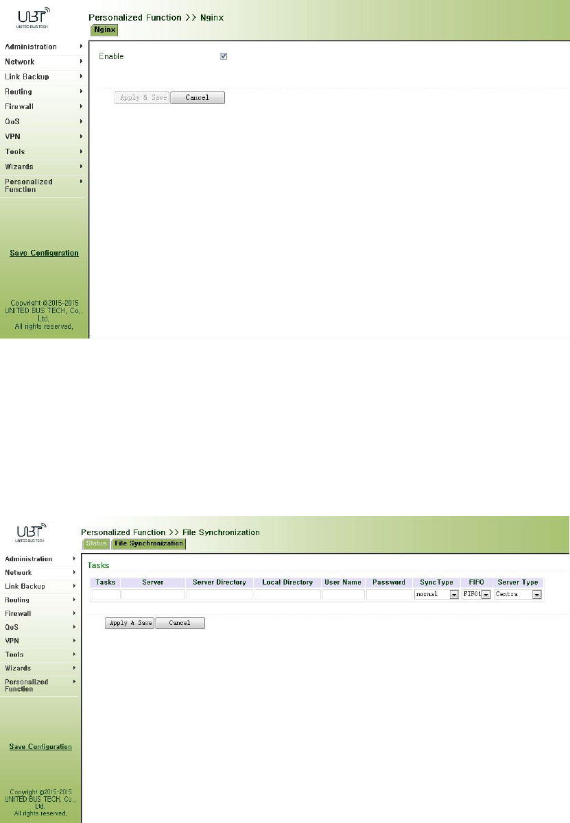
Fromnavigationpanel"PersonalizedFunction/Nginx"menu,enter"Nginx"page,asshownin
Figure3‐69.
Figure3‐69Nginx
3.8.2FileSynchronization
Fromnavigationpanel"PersonalizedFunction/FileSynchronization"menu,enter"File
Synchronization"page,asshowninFigure3‐70.
Figure3‐70FileSynchronization
PagedescriptionisshowninTable3‐41.
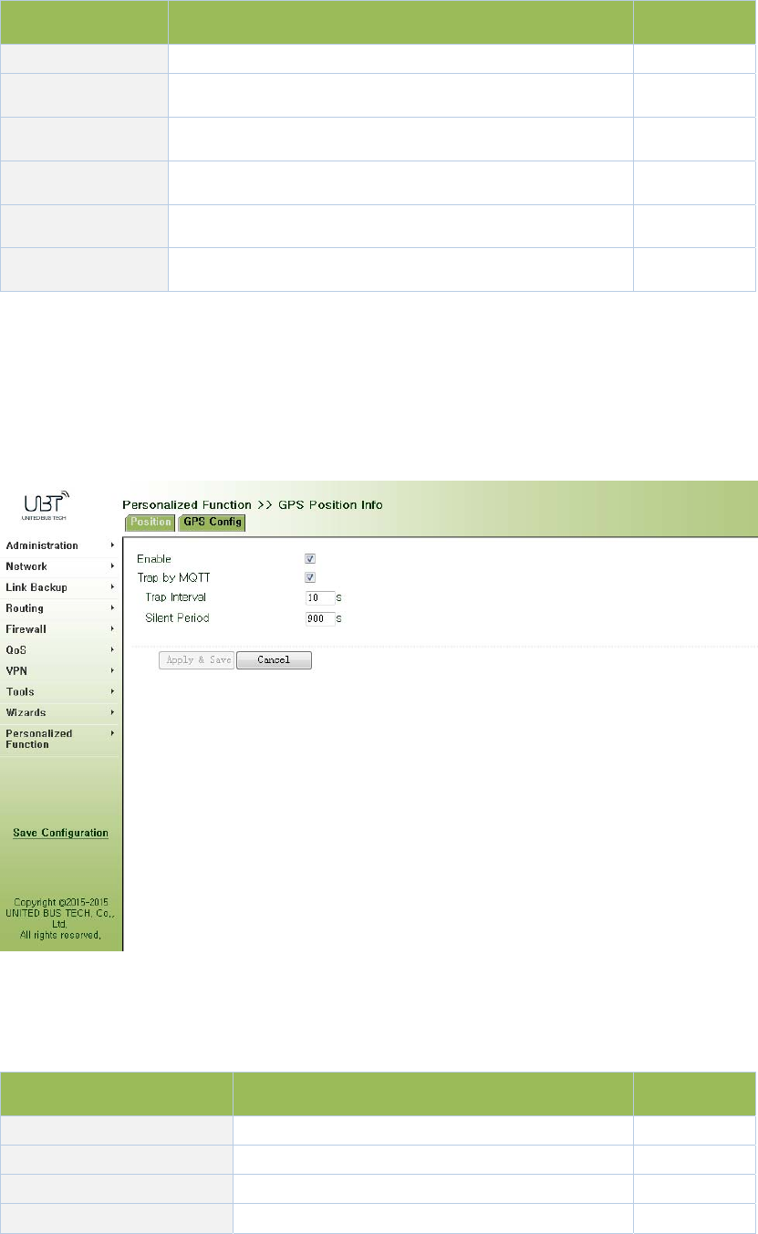
Table3‐41FileSynchronizationDescription
ParametersDescriptionDefault
TaskUser‐definedtasknameNone
ServerRsyncServerAddressNone
ServerDirectorySynchronizefilestoRsyncserveraddressNone
LocalDirectorySynchronizefilestolocaldirectoryNone
UsernameRsyncservernameNone
Password RsyncserverpasswordNone
3.8.3GPSLocationInformation
Fromnavigationpanel"PersonalizedFunction/GPSConfig"menu,enter"GPSConfig"page,
showninFigure3‐71.
Figure3‐71GPSSettings
PagedescriptionisshowninTable3‐42.
Table3‐42GPSConfigDescription
ParametersDescriptionDefault
Server uploadlocationinformationserverIPaddressNone
Port Uploadlocationinformationserverport80
PositioningtimeintervalSetpositioningtimeinterval60
UploadLocationSetuploadLocationinformationgap60
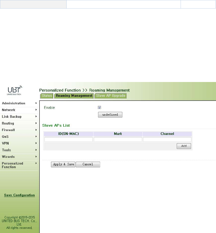
informationgap
3.8.4RoamingManagement
3.8.4.1RoamingManagement
Fromnavigationpanel“PersonalizedFunction/RoamingManagement"menu,enter"Roaming
Management"page,showninFigure3‐72.
Figure3‐72RoamingManagement
3.8.4.2UpgradefromAP
Fromnavigationpanel"PersonalizedFunction/RoamingManagement"menu,enter"SlaveAP
Upgrade"page,asshowninFigure3‐73.
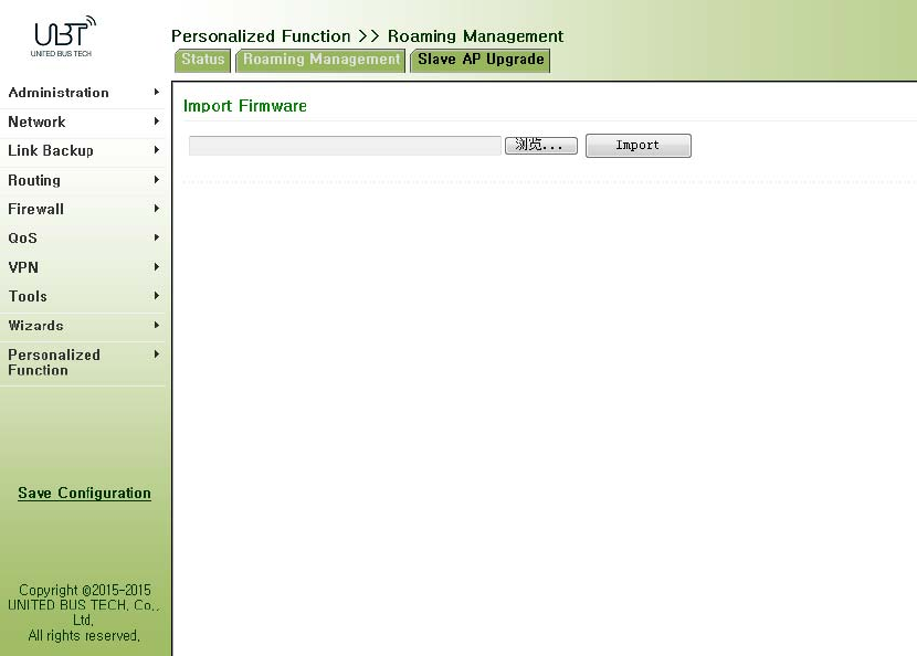
Figure3‐73SlaveAPUpgrade
3.9Firewall
Withtheexpansionofnetworkandincreaseinflow,thecontrolovernetworksafetyandthe
allocationofbandwidthbecometheimportantcontentsofnetworkmanagement.Thefirewall
functionoftherouterimplementscorrespondingcontroltodataflowatentrydirection(from
Internettolocalareanetwork)andexitdirection(fromlocalareanetworktoInternet)according
tothecontentfeaturesofmessage(suchas:protocolstyle,source/destinationIPaddress,etc.)
andensuressafeoperationofrouterandhostinlocalareanetwork.
3.9.1AccessControl(ACL)
ACL,namelyaccesscontrollist,implementspermissionorprohibitionofaccessforappointed
dataflow(suchasprescribedsourceIPaddressandaccountnumber,etc.)viaconfigurationofa
seriesofmatchingrulessoastofilterthenetworkinterfacedata.Aftermessageisreceivedby
portofrouter,thefieldisanalyzedaccordingtoACLruleappliedonthecurrentport.Andafter
thespecialmessageisidentified,thepermissionorprohibitionofcorrespondingpacketis
implementedaccordingtopresetstrategy.
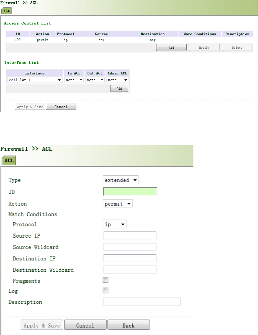
ACLclassifiesdatapackagesthroughaseriesofmatchingconditions.Theseconditionscanbe
datapackages’sourceMACaddress,destinationMACaddress,sourceIPaddress,destinationIP
address,portnumber,etc.
ThedatapackagematchingrulesasdefinedbyACLcanalsobeusedbyotherfunctionsrequiring
flowdistinguish.
Fromnavigationpanel,selectFirewall/ACL,thenenter“ACL”page,asshowninFigure3‐74‐1.
Figure3‐74‐1AccessControl(ACL)
Click<Add>toaddnewaccesscontrollist,asshowninFigure3‐74‐2.

Figure3‐74‐2AccessControl(ACL)
PagedescriptionisshowninTable3‐43.
Table3‐43AccessControlDescription
ParametersDescriptionDefault
Type
StandardACLcanblockallcommunicationflowsfroma
network,orallowallcommunicationflowsfroma
particularnetwork,ordenyallcommunicationflowsofa
protocolstack(e.g.IP)of.
TheextendedACLprovidesawiderrangeofcontrolthan
thatprovidedbythestandardACL.Forexample,ifthe
networkadministratorwantsto"allowexternalWeb
communicationflowstopassthroughandrejectexternal
communicationflows,e.g.FTPandTel ne t ”,theextended
ACLcanbeusedtoachievetheobjective.Thestandard
ACLcannotbecontrolledsoprecisely.
Extended
IDUserdefineNone
ActionPermit/Deny Permit
ProtocolAccessControlProtocolip
SourceIPAddress IPAddressofSourceNone
DestinationIP IPAddressofDestinationNone
DestinationIP
addressDestinationnetworkaddressNone
DestinationInvert
Mask DestinationaddressmaskinvertedNone
LoggingClickEnable,thesystemwillrecordaccesscontrolona
logDisable
Description EasytorecordcontrolaccessparametersonalogNone
NetworkInterfacelist
InterfaceNameSelectInterfaceNamecellular1
Rules Selectinbound,outboundandmanagementrulesnone
3.9.2NAT
NATcanachieveInternetaccessbymultiplehostswithintheLANthroughoneormorepublic
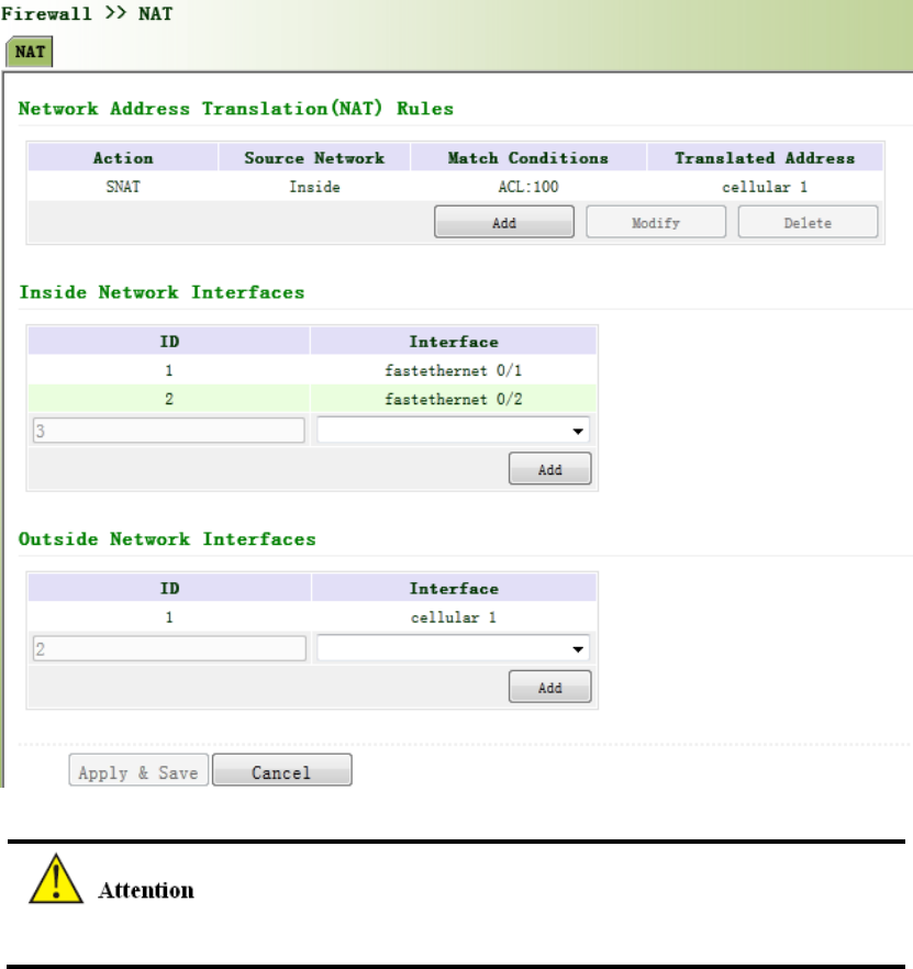
networkIPaddresses.ItmeansthatfewpublicnetworkIPaddressesrepresentmoreprivate
networkIPaddresses,thussavingpublicnetworkIPaddresses.
Fromnavigationpanel,selectFirewall/NAT,thenenter“NAT”page,asshowninFigure3‐75‐1.
Figure3‐75‐1NAT
NATruleistoapplyACLtoaddresspool,onlymatchingtheACLaddressbeforeconversion.
Click<Add>toaddnewNATrules,asshowninFigure3‐75‐2.

Figure3‐75‐2NAT
PagedescriptionisshowninTable3‐44.
Table3‐44NATDescription
ParametersDescriptionDefault
Action
SNAT:SourceNAT:TranslateIPpacket'ssourceaddress
intoanotheraddress
DNAT:DestinationNAT:Mapasetoflocalinternal
addressestoasetoflegalglobaladdresses.
1:1NAT:TransferIPaddressonetoone.
SNAT
SourceNetwork
Inside:Insideaddress
Outside:Outsideaddress
Inside
TranslationTypeSelecttheTranslationTypeIPtoIP
PrivatenetworkIPaddressreferstotheIPaddressofinternalnetworkorhost,whilepublic
networkIPaddressisagloballyuniqueIPaddressontheInternet.
RFC1918threeIPaddressblocksfortheprivatenetworkasfollows:
ClassA:10.0.0.0~10.255.255.255

ClassB:172.16.0.0~172.31.255.255
ClassA:192.168.0.0~192.168.255.255
TheaddresseswithintheabovethreerangeswillnotbeallocatedontheInternet.Therefore,
theycanbefreelyusedincompaniesorenterpriseswithouttheneedtomakeapplicationtothe
operatororregistrationcenter
3.10QoS
InthetraditionalIPnetwork,allpacketsaretreatedequallywithoutdistinction.Eachnetwork
deviceusesfirstinfirstoutstrategyforpacketprocessing.Thebest‐effortnetworksendspackets
tothedestination,butitcannotguaranteetransmissionreliabilityanddelay.
QoScancontrolnetworktraffic,avoidandmanagenetworkcongestion,andreducepacket
droppingrate.Someapplicationsbringconveniencetousers,buttheyalsotakeupalotof
networkbandwidth.ToensureallLANuserscannormallygetaccesstonetworkresources,IP
trafficcontrolfunctioncanlimittheflowofspecifiedhostonlocalnetwork.
QoSprovidesuserswithdedicatedbandwidthanddifferentservicequalityfordifferent
applications,greatlyimprovingthenetworkservicecapabilities.Userscanmeetvarious
requirementsofdifferentapplicationslikeguaranteeinglowlatencyoftime‐sensitivebusiness
andbandwidthofmultimediaservices.
QoScanguaranteehighprioritydataframesreceiving,acceleratehigh‐prioritydataframe
transmission,andensurethatcriticalservicesareunaffectedbynetworkcongestion.IR900
supportsfourservicelevels,whichcanbeidentifiedbyreceivingportofdataframe,Tagpriority
andIPpriority.
Fromnavigationpanel,selectQos/TrafficControl,thenenter“TrafficControl”page,asshownin
Figure3‐76.

Figure3‐76QoS
PagedescriptionisshowninTable3‐45.
Table3‐45QoSDescription
ParametersDescriptionDefault
Type
NameNameName
AnyPackets ClickStartupforflowcontroltoanypackets Disable
Source SourceaddressofflowcontrolN/A
Destination DestinationaddressofflowcontrolN/A
Protocol ClicktoselectprotocolstyleN/A
Policy
NameNameofuserdefinedflowcontrolstrategyN/A
Classifier NameofstyledefinedaboveN/A
GuaranteedBandwidth
Kbps
Userdefinedguaranteedbandwidth
N/A
MaximumBandwidthKbpsUserdefinedmaximumbandwidthN/A
LocalPriorityLocalpriorityofselectionstrategyN/A
ApplyQos
InterfaceSelectionofflowcontrolinterfacecellular1
IngressMaxbandwidth
Kbps
Userdefine,biggerthanmaximumbandwidthof
inputstrategy
N/A

EgressMaxbandwidthKbps
Userdefine,biggerthanmaximumbandwidthof
outputstrategy
N/A
IngressPolicy NameofpolicydefinedaboveN/A
EgressPolicyNameofpolicydefinedaboveN/A
3.11VPN
VPNisanewtechnologythatrapidlydevelopedinrecentyearswiththeextensiveapplicationof
Internet.Itisforbuildingaprivatededicatednetworkonapublicnetwork.'Virtuality"mainly
referstothatthenetworkisalogicalnetwork.
TwoBasicFeaturesofVPN:
Private:theresourcesofVPNareunavailabletounauthorizedVPNusersontheinternet;
VPNcanensureandprotectitsinternalinformationfromexternalintrusion.
Virtual:thecommunicationamongVPNusersisrealizedviapublicnetworkwhich,
meanwhilecanbeusedbyunauthorizedVPNuserssothatwhatVPNusersobtainedisonly
alogisticprivatenetwork.ThispublicnetworkisregardedasVPNBackbone.
FundamentalPrincipleofVPN
ThefundamentalprincipleofVPNindicatestoencloseVPNmessageintotunnelwithtunneling
technologyandtoestablishaprivatedatatransmissionchannelutilizingVPNBackbonesoasto
realizethetransparentmessagetransmission.
Tunnelingtechnologyenclosestheotherprotocolmessagewithoneprotocol.Also,encapsulation
protocolitselfcanbeenclosedorcarriedbyotherencapsulationprotocols.Totheusers,tunnelis
logicalextensionofPSTN/linkofISDN,whichissimilartotheoperationofactualphysicallink.
ThecommontunnelprotocolsincludeL2TP,PPTP,GRE,IPSec,MPLS,etc.
3.11.1IPSec
AmajorityofdatacontentsarePlaintextTransmissionontheInternet,whichhasmanypotential
dangerssuchaspasswordandbankaccountinformationstolenandtampered,useridentity
imitated,sufferingfrommaliciousnetworkattack,etc.AfterdisposalofIPSeconthenetwork,it
canprotectdatatransmissionandreduceriskofinformationdisclosure.
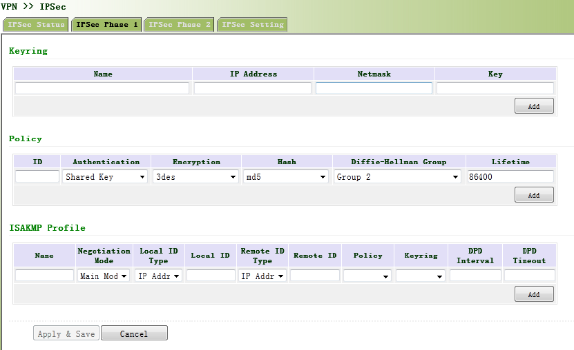
IPSecisagroupofopennetworksecurityprotocolmadebyIETF,whichcanensurethesecurityof
datatransmissionbetweentwopartiesontheInternet,reducetheriskofdisclosureand
eavesdropping,guaranteedataintegrityandconfidentialityaswellasmaintainsecurityofservice
transmissionofusersviadataoriginauthentication,dataencryption,dataintegrityand
anti‐replayfunctionontheIPlevel.
IPSec,includingAH,ESPandIKE,canprotectoneandmoredateflowsbetweenhosts,between
hostandgateway,andbetweengateways.ThesecurityprotocolsofAHandESPcanensure
securityandIKEisusedforciphercodeexchange.
IPSeccanestablishbidirectionalSecurityAllianceontheIPSecpeerpairstoformasecureand
interworkingIPSectunnelandtorealizethesecuretransmissionofdataontheInternet.
3.11.1.1IPSecPhase1
IKEcanprovideautomaticnegotiationciphercodeexchangeandestablishmentofSAforIPSecto
simplifytheoperationandmanagementofIPSec.Theself‐protectionmechanismsofIKEcan
completeidentityauthenticationandkeydistributioninaninsecurenetwork.
Fromnavigationpanel,selectVPN/IPSec,thenenter“IPSecPhase1”page,asshowninFigure
3‐77.
Figure3‐77IPSecPhase1

PagedescriptionisshowninTable3‐46.
Table3‐46IPSecPhase1Description
Parameters DescriptionDefault
Keyring
Name Userdefinekey N/A
IPAddress End‐to‐endIPaddressN/A
SubnetMaskEnd‐to‐endsubnetmaskN/A
KeyUserdefinekeycontentN/A
IKEPolicy
Identification PolicyidentificationofuserdefinedIKE N/A
Authentication Alternativeauthentication:sharedkeyanddigitalcertificate
Shared
key
Encryption
3des:encryptplaintextwiththreeDESciphercodesof64bit
des:encrypta64bitplaintextblockwith64bitciphercode
Aes:encryptplaintextblockwithAESAlgorithmwithcipher
codelengthof128bit,192bitor256bit
3des
Hash
md5:inputinformationofarbitrarylengthtoobtain128bit
messagedigest.
sha‐1:inputinformationwithshorterlengthofbittoobtain
160bitmessagedigest.
Comparingboth,md5isfasterwhilesha‐1issafer.
md5
Diffie‐Hellman
KeyExchange
Threeoptions:Group1,Group2andGroup5Group2
LifetimeActivetimeofpolicy 86400
ISAKMPProfile
Name NameofuserdefinedISAKMPProfileN/A
Negotiation
Mode
Mainmode:asanexchangemethodofIKE,mainmodeshallbe
establishedinthesituationwherestricteridentityprotectionis
required.
Aggressivemode:asanexchangemethodofIKE,aggressive
Main
mode

modeexchangingfewermessage,canacceleratenegotiationin
thesituationwhereordinaryidentityprotectionisrequired.
LocalIDTypeSelecttypeoflocalidentification
IP
Address
LocalIDThelocalIDcorrespondingtotheselectedlocalIDN/A
RemoteID
Type
SelecttypeofRemoteID
IP
Address
RemoteID
TheRemoteIDcorrespondingtotheselectedpeer
identification
N/A
Policy ThedefinedstrategyidentificationintheIKEStrategylist
N/A
KeyRingThedefinedkeysetinthekeysetlist
N/A
DPDInterval
UsedfordetectionintervalofIPSecneighborstate.
AfterinitiatingDPD,IfreceivingendcannotreceiveIPSec
cryptographicmessagesentbypeerendwithinintervalof
triggeringDPD,receivingendcanmakeDPDcheck,send
requestmessagetooppositeendautomatically,detectwhether
IKEpeerpairexists.
N/A
DPDTimeout
ReceivingendwillmakeDPDcheckandsendrequestmessage
automaticallytooppositeendforcheck.Ifitdoesnotreceive
IPSeccryptographicmessagefrompeerendbeyondtimeout,
ISAKMPProfilewillbedeleted.
N/A
Thesecuritylevelofthreeencryptionalgorithmsrankssuccessively:AES,3DES,DES.The
implementationmechanismofencryptionalgorithmwithstrictersecurityiscomplexandslow
arithmeticspeed.DESalgorithmcansatisfytheordinarysafetyrequirements.

3.11.1.2IPSecPhase2
Fromnavigationpanel,selectVPN>>IPSec,thenenter“IPSecPhase2”page,asshowninFigure
3‐78.
Figure3‐78IPSecPhase2
PagedescriptionisshowninTable3‐47.
Table3‐47IPSecIPSecPhase2Description
ParametersDescriptionDefault
Name UserdefineTransformSetname N/A
Encapsulation
Chooseencapsulationformsofdatapacket
AH:protectintegrityandauthenticityofdatapacketfrom
hackerinterceptingdatapacketorinsertingfalsedata
packetontheinternet.
ESP:encrypttheuserdataneedingprotection,andthen
encloseintoIPpacketforthepurposeofconfidentialityof
data.
esp
Encryption Threeoptions:AES,3DES,DES3des
AuthenticationAlternativeauthentication:md5andsha‐1md5
IPSecMode
TunnelMode:besidessourcehostanddestinationhost,
specialgatewaywillbeoperatedwithpasswordtoensure
thesafetyfromgatewaytogateway.
TransmissionMode:sourcehostanddestinationhostmust
directlybeoperatedwithallpasswordsforthepurposeof
higherworkefficiency,butcomparingwithtunnelmodethe
Tunnel
Mode
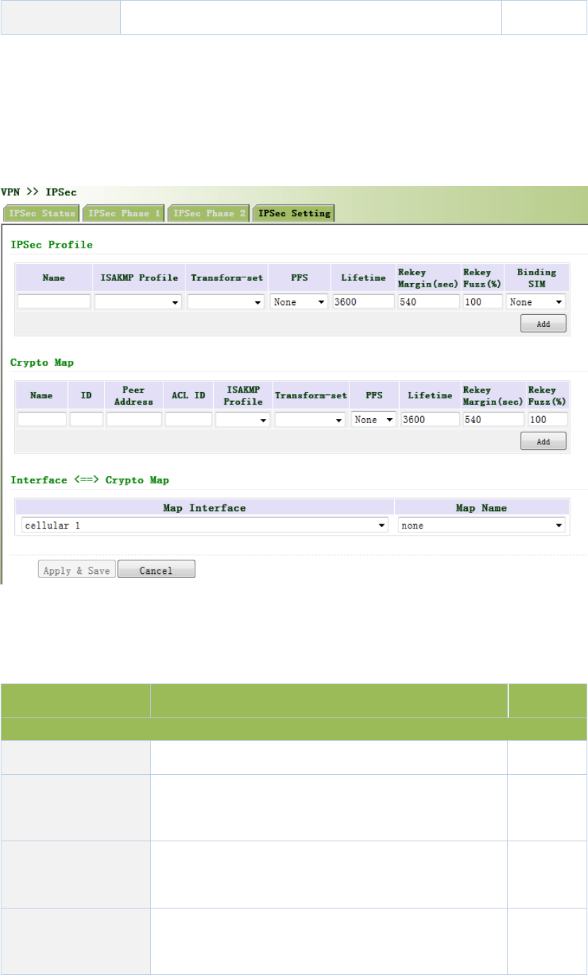
securitywillbeinferior.
3.11.1.3IPSecConfiguration
Fromnavigationpanel,selectVPN/IPSec,thenenter“IPSecSetting”page,asshownin
Figure3‐79.
Figure3‐79IPSecConfiguration
PagedescriptionisshowninTable3‐48.
Table3‐48IPSecConfigurationDescription
ParametersDescriptionDefault
IPSecProfile
NameUserdefineIPSecProfilenameN/A
ISAKMPProfile
ISAKMPProfilenamesdefinedinthefirststageof
parametersofIPSec
N/A
TransformSet
TransformSetdefinedinthefirststageofparametersof
IPSec
N/A
PerfectForward
Security(PFS)
Meanstherevealofoneciphercodewillnotendanger
informationprotectedbyotherciphercodes.
Disable

LifetimeLifetimeofIPSecProfile3600
RekeyMargin(S)Reconnectiontimeforthesecondstage540
RekeyFuzz(%)
Deviationpercentageofthereconnectiontimeforthe
secondstage
100
SIMCardBinding
Withthisfunctionactivated,successfuldialingofthe
cardwithwhichIPSecisbondedisapreconditionforthe
useofIPSec.
Disable
CryptoMap
NameUserdefinenameofcryptomapN/A
IDUserdefineIDofcryptomapN/A
PeerAddressPeerIPAddressN/A
ACLIDIDofACLdefinedinACLoffirewallN/A
ISAKMPProfile
ISAKMPProfilenamesdefinedinthefirststageof
parametersofIPSec
N/A
TransformSet
TransformSetdefinedinthefirststageofparametersof
IPSec
N/A
PerfectForward
Security(PFS)
Meanstherevealofoneciphercodewillnotendanger
informationprotectedbyotherciphercodes.
Disable
LifetimeValidityofCryptoMap3600
RekeyMargin(S)Reconnectiontimeforthesecondstage540
RekeyFuzz(%)
Deviationpercentageofthereconnectiontimeforthe
secondstage
100
ParametersDescriptionDefault
Interface<==>CryptoMap
MAPInterface SelectInterfaceNamecellular1
MapName
SelectfromdefinednamesofCryptoMap.Onenameis
matchedwithseveralmarks.
none
3.11.1.4IPSecVPNConfigurationExample
BuildingasecurechannelbetweenRouterAandRouterBtoensurethesecuredataflow
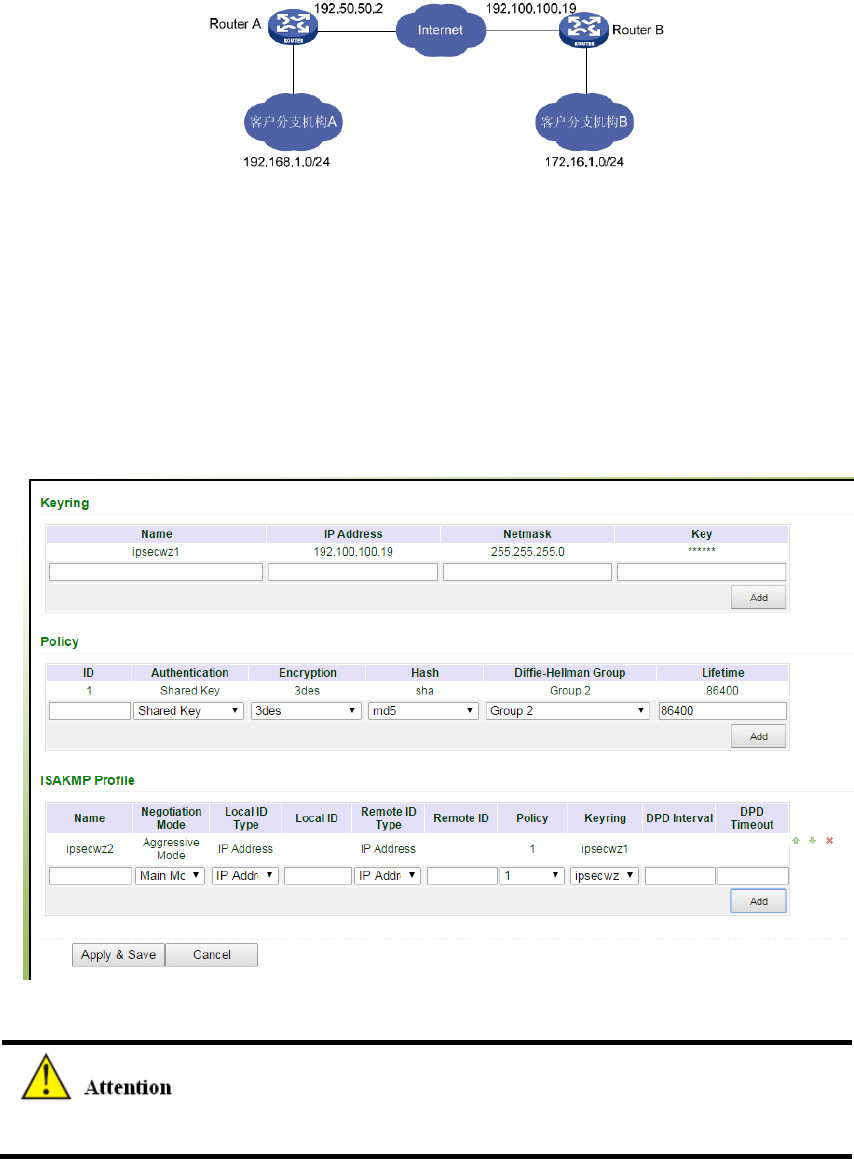
betweenCustomerBranchA‘ssubnet(192.168.1.0/24)andCustomerBranchB‘ssubnet
(172.16.1.0/24).SecurityprotocolisESP,theencryptionalgorithmis3DES,andauthentication
algorithmisSHA.
Thetopologyisasfollows:
ConfigurationSteps:
(1)RouterASettings
Step1:IPSecSettingPhase1
Fromnavigationpanel,selectVPN/IPSec,thenenter“IPSecSettingPhase1”page,asshown
below.
NoneedtofillinLocalIDTypeandRemoteIDType.
Step2:IPSecSettingPhase2
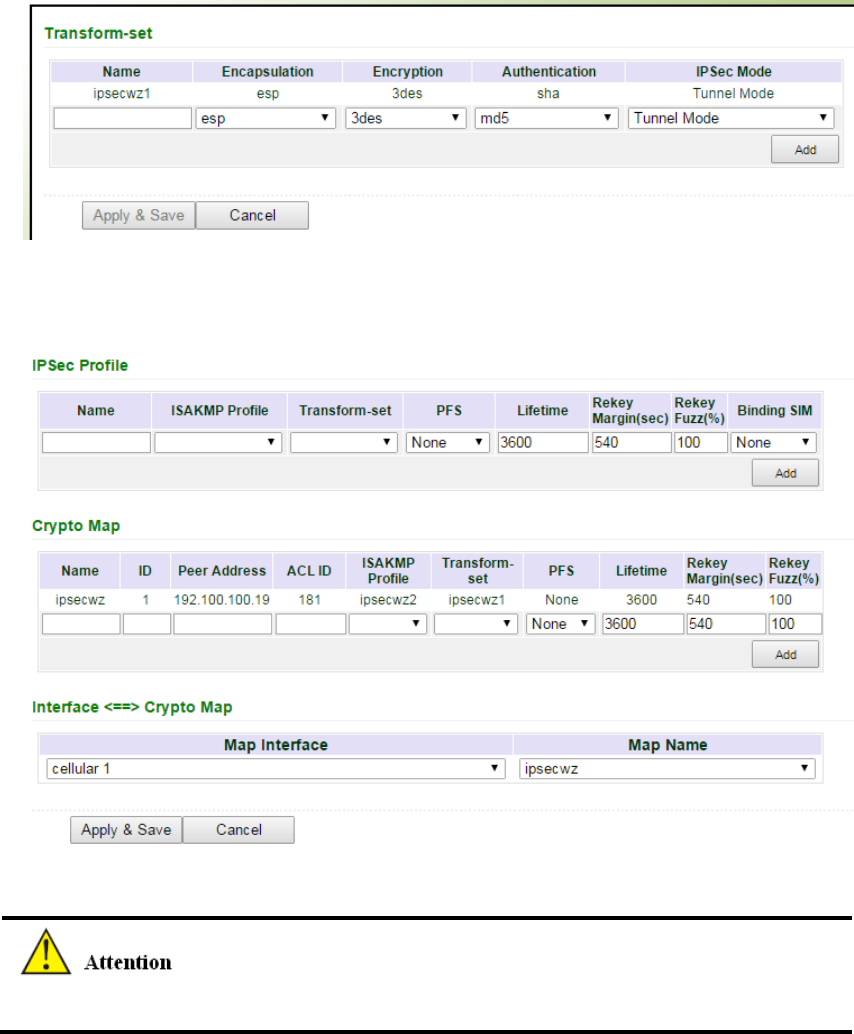
Fromnavigationpanel,selectVPN/IPSec,thenenter“IPSecSettingPhase2”page,asshown
below.
Step3:IPSecSetting
Fromnavigationpanel,selectVPN/IPSec,thenenter“IPSecSetting”page,asshownbelow.
IPSecProfilesettingisneededonlywhenit’sDMVPN.
(2)RouterBSettings
Step1:IPSecSettingPhase1
Fromnavigationpanel,selectVPN/IPSec,thenenter“IPSecSettingPhase1”page,asshown
below.
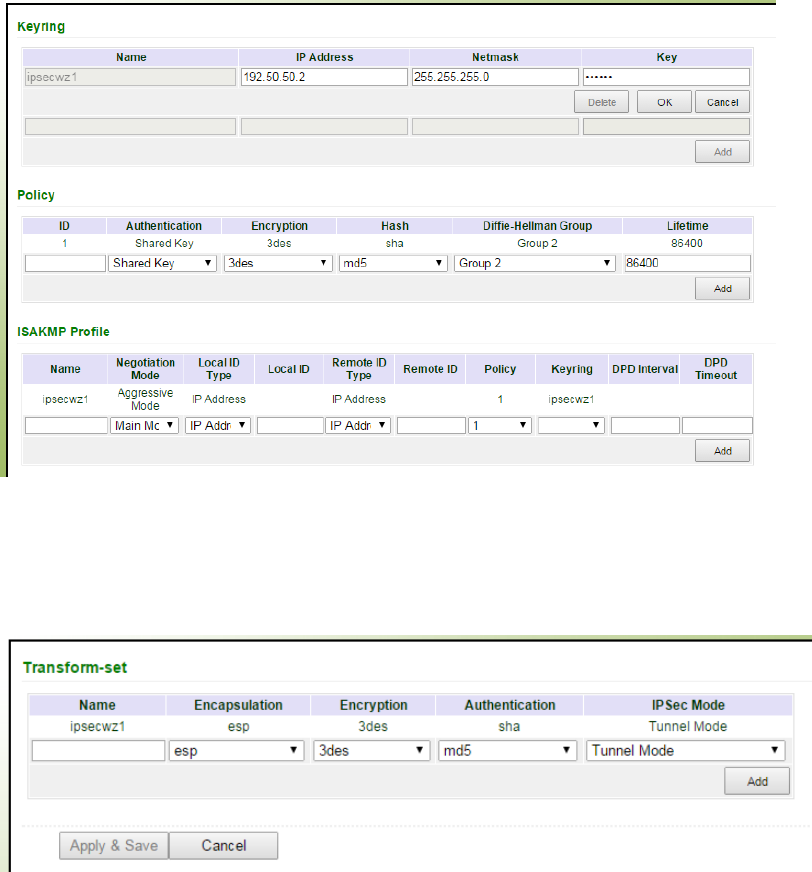
Step2:IPSecSettingPhase2
Fromnavigationpanel,selectVPN/IPSec,thenenter“IPSecSettingPhase2”page,asshown
below.
Step3:IPSecSetting
Fromnavigationpanel,selectVPN/IPSec,thenenter“IPSecSetting”page,asshownbelow.
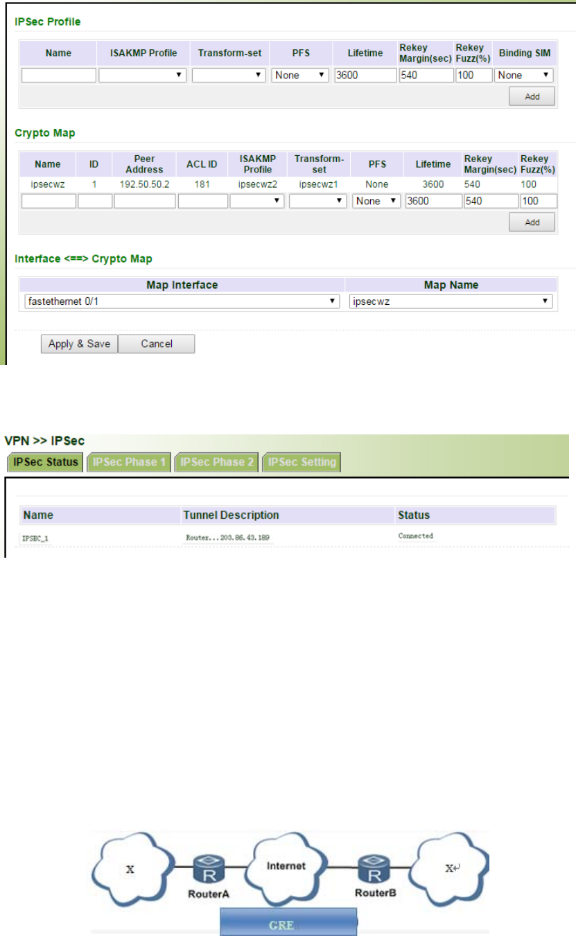
(3)VPNStatusChecking
Fromnavigationpanel,selectVPN/IPSec,thenenter“IPSecStatus”page,asshownbelow.
3.11.2GRE
GenericRouteEncapsulation(GRE)definestheencapsulationofanyothernetworklayerprotocol
onanetworklayerprotocol.GREcouldbeusedastheL3TPofVPNtoprovideatransparent
transmissionchannelforVPNdata.Insimpleterms,GREisatunnelingtechnologywhichprovides
achannelthroughwhichencapsulateddatamessagecouldbetransmittedandencapsulationand
decapsulationcouldberealizedatbothends.GREtunnelapplicationnetworkingshownasthe
followingfigure:
AlongwiththeextensiveapplicationofIPv4,tohavemessagesfromsomenetworklayerprotocol
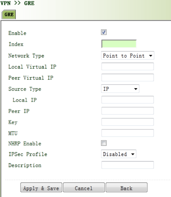
transmittedonIPv4network,thosemessagescouldbyencapsulatedbyGREtosolvethe
transmissionproblemsbetweendifferentnetworks.
InfollowingcircumstancesGREtunneltransmission:
GREtunnelcouldtransmitmulticastdatapacketsasifitwereatruenetworkinterface.
SingleuseofIPSeccannotachievetheencryptionofmulticast.
Acertainprotocoladoptedcannotberouted.
AnetworkofdifferentIPaddressshallberequiredtoconnectothertwosimilarnetworks.
GREapplicationexample:combinedwithIPSectoprotectmulticastdata
GREcanencapsulateandtransmitmulticastdatainGREtunnel,butIPSec,currently,couldonly
carryoutencryptionprotectionagainstunicastdata.Incaseofmulticastdatarequiringtobe
transmittedinIPSectunnel,aGREtunnelcouldbeestablishedfirstforGREencapsulationof
multicastdataandthenIPSecencryptionofencapsulatedmessagesoastoachievethe
encryptiontransmissionofmulticastdatainIPSectunnel.
Fromnavigationpanel,selectVPN/GRE,thenenter“GRE”page,asshowninFigure3‐80.
Figure3‐80GRESettings
PagedescriptionisshowninTable3‐49.

Table3‐49GREDescription
ParametersDescriptionDefault
Enable Clicktoopen Open
Index SetGREtunnelname None
NetworkTypeSelectGREnetworktype peerto
peer
LocalVirtualIPSetLocalVirtualIPAddressNone
PeerVirtualIPSetPeerVirtualIPAddressNone
SourceTypeSelectsourcetypeandsettheaccordingIPaddressorinterfaceIP
LocalIPSetLocalIPAddressNone
PeerIPSetPeerIPAddress None
KeySetthekeyoftunnelNone
MTUSetthemaximumtransmission,unitinbytesNone
EnableNHRP
NextHopResolutionProtocol,usedtoconnectto
non‐broadcastmultipleaccess(NBMA)formulasubnetwork
sourcestation(hostorrouter)decidedtoreach"NBMAnext
hop"internetworkinglayeraddressandNBMAsubnetwork
betweenthedestinationstationaddress.
Enable
Description AdddescriptionNone
3.11.3L2TP
L2TP,oneofVPDNTPs,hasexpandedtheapplicationsofPPP,knownasaveryimportantVPN
technologyforremotedial‐inusertoaccessthenetworkofenterpriseheadquarters.
L2TP,throughdial‐upnetwork(PSTN/ISDN),basedonnegotiationofPPP,couldestablishatunnel
betweenenterprisebranchesandenterpriseheadquarterssothatremoteuserhasaccesstothe
networkofenterpriseheadquarters.PPPoEisapplicableinL2TP.Throughtheconnectionof
EthernetandInternet,aL2TPtunnelbetweenremotemobileofficersandenterprise
headquarterscouldbeestablished.
L2TP‐Layer2TunnelProtocol,encapsulatesprivatedatafromusernetworkattheheadofL2PPP.
Noencryptionmechanismisavailable,thusIPSesisrequiredtoensuresafety.
MainPurpose:branchesinotherplacesandemployeesonabusinesstripcouldaccessto
thenetworkofenterpriseheadquarterthroughavirtualtunnelbypublicnetworkremotely.
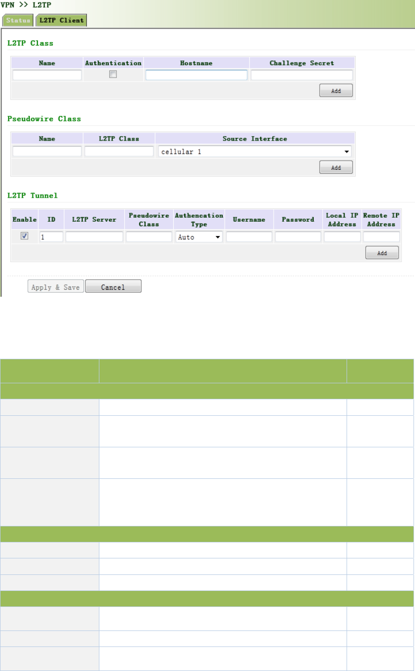
Fromnavigationpanel,selectVPN/L2TP,thenenter“L2TPClient”page,asshowninFigure3‐81.
Figure3‐81L2TPClient
PagedescriptionisshowninTable3‐50.
Table3‐50L2TPClientDescription
ParametersDescriptionDefault
L2TPClass
NameUserdifineL2TPClassNameNone
AuthenticationClickEnable,peerauthenticationisrequiredtonetwork
connectionwhenenable.Disable
HostNameNetworkconnectiontolocalhostname,notto
configure.None
Tunnel
Authenticationkey
Whenthetunnelmustbeconfiguredtoenablethe
authentication,clickauthenticationkey,oryouwillnot
needtoconfigure.
None
PseudowireClass
Name UserdifinePseudowireClassNameNone
L2TPClassL2TPClassnameNone
SourceInterfaceSeclectsourceinterfacenamecellular1
L2TPTunnel
Enable Clicktoenable Enable
IndexAutomaticgenerated1
L2TPServerSetL2TPServeraddressNone

PseudowireClassPseudowireClassnameNone
AuthenticationType SelectAuthenticationType Auto
UsernamePeerServerusername None
PasswordPeerServerpasswordNone
LocalIPAddress SetlocalIPaddress,orautomaticallyallocatedbypeer
server.
None
RemoteIPAddressSetremoteIPaddres,ornotNone
3.11.4OPENVPN
SinglepointparticipatingintheestablishmentofVPNisallowedtocarryoutIDverificationby
presetprivatekey,third‐partycertificateorusername/password.OpenSSLencryptionlibraryand
SSLv3/TLSv1protocolaremassivelyused.
InOpenVpn,ifauserneedstoaccesstoaremotevirtualaddress(addressfamilymatchingvirtual
networkcard),thenOSwillsendthedatapacket(TUNmode)ordataframe(TAPmode)tothe
visualnetworkcardthroughroutingmechanism.Uponthereception,serviceprogramwill
receiveandprocessthosedataandsendthemoutthroughouternetbySOCKET,owingtowhich,
theremoteserviceprogramwillreceivethosedataandcarryoutprocessing,thensendthemto
thevirtualnetworkcard,thenapplicationsoftwarereceiveandaccomplishacomplete
unidirectionaltransmission,viceversa.
Fromnavigationpanel,selectVPN/OPENVPN,thenenter“OPENVPNClient”page,asshownin
Figure3‐82.
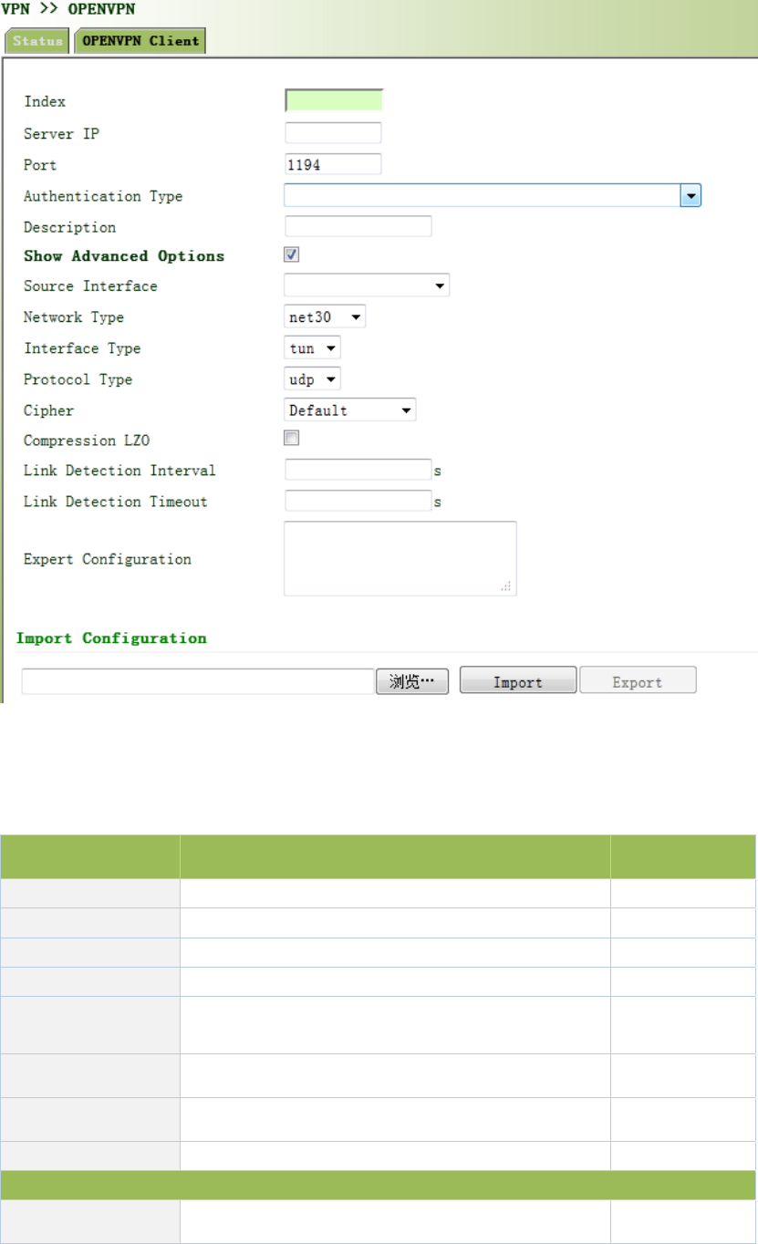
Figure3‐82OPENVPNClient
PagedescriptionisshowninTable3‐51.
Table3‐51OPENVPNOPENVPNClientDescription
ParameterDescriptionDefault
EnableClickEnableEnable
IDSetchannelIDNone
ServerIPAddressSetpeerserverIPaddresssNone
PortNumberSetpeerserverportnumber1194
AuthenticationType Selectandconfigureauthenticationtypeparameters
oftypecertification
User
name/Password
UsernameKeepconsistencywithserver None
Password KeepconsistencywithserverNone
Channeldescription userdefinechanneldescriptionNone
AdvancedOptions
SourcePortSelectsourceportnameNone

NetworkTypeSelectnetworktypenet30
PortTypeSelectdataformissuedfromtheinterface.tun‐
packet,tap‐dataframetun
ProtocolType Keepconsistencywithserverprotocoludp
AdvancedOptions
Encryption
AlgorithmkeepconsistencywithserverDefault
LZOCompressionClickEnableOff
ConnectionTesting
Interval
Setconnectingtestingtimeinterval
None
ConnectionTesting
Overtime
Setconnectingtestingovertime
None
Expert
Configuration
Setexpertoption:blankadvisable
None
Importconfigurationscanbedirectlyimportedintotheconfigureddocumentsgeneratedfrom
backendserverandmanualconfigurationofOPENVPNcustomerendparameterisinnoneed
afterimport.
3.11.5CertificateManagement
Fromnavigationpanel,selectVPN/CertificateManagement,thenenter“Certificate
Management”page,asshowninFigure3‐83.

Figure3‐83CertificateManagement
PagedescriptionisshowninTable3‐52.
Table3‐52CertificateManagementDescription
ParameterDescriptionDefault
Forcedtore‐apply
Ifthecertificatehasnotexpired,butneedtoreapply,click
forcedtore‐apply,re‐configurethecertificaterequest
parameter.
Disable
RequestStatussuccessfulapplication,"RequestStatus"shows:
CompletionInitiation
Certificate
ProtectionKey
Setcertificateprotectionkey
None
Certificate
ProtectionKey
Confirmation
Confirmcertificateprotectionkey None
ServerURLSetcertificateserverIPNone
CertificatenameSetcertificatenameNone
FQDNSetfulldomainnameNone
UnitName1Setunitname1None
UnitName2Setunitname2None
DomainName SetdomainnameNone
SerialNumberSetapplicationcertificateserialnumberNone
Authentication
PasswordSetauthenticationpasswordNone
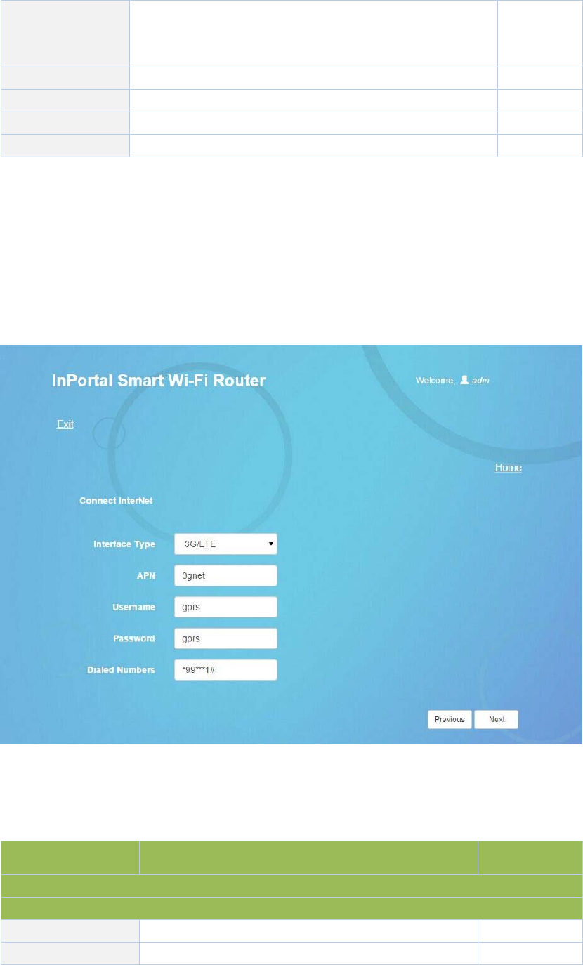
Authentication
Password
Confirmation
Confirmauthenticationpassword
None
HostIPSetrouteraddressintheuseofcertificateapplicationNone
RSAKeylengthSetRSAkeylength1024
QueryIntervalSetqueryinterval60sec
QueryTimeoutSetquerytimeout3600sec
3.12ConfigurationWizard
AfterlogintheconfigurationpageviaWeb,click“ConnectInternet”toenterconfigurationpage
below:
Figure3‐12‐1ConnectInternet
Pagedescription:
Table3‐12‐1ConnectInternetConfigurationDescription
ParametersDescriptionDefault
InterfaceType:3G/LTE,ADSL,DHCPandStaticIPAddress
3G/LTE
APNProvidedbylocaloperator3gnet
UsernameProvidedbylocaloperatorgprs
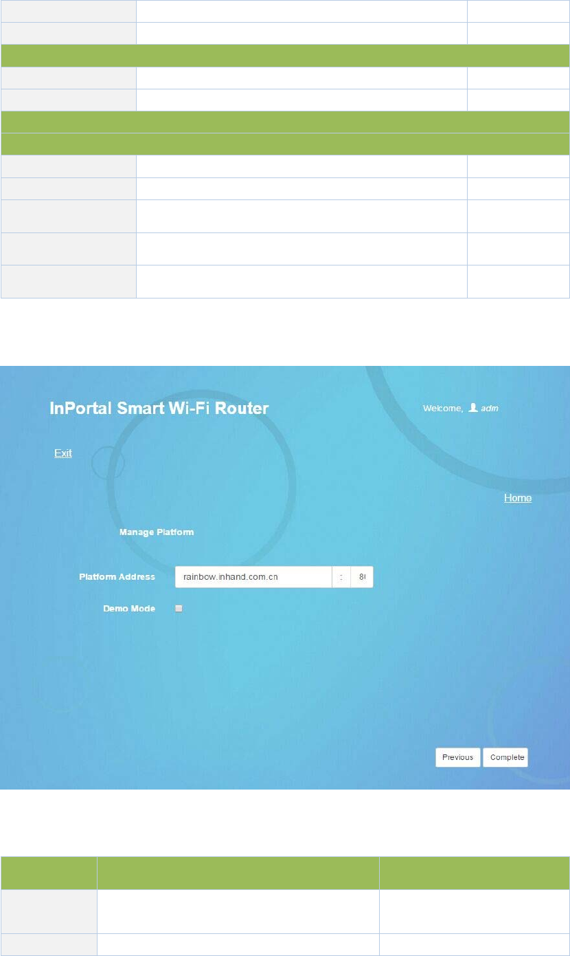
PasswordProvidedbylocaloperatorgprs
DialedNumbersProvidedbylocaloperator*99***1#
ADSL
UsernameProvidedbylocaloperatorN/A
PasswordProvidedbylocaloperatorN/A
NoconfigurationforDHCP
StaticIPAddress
IPAddress Userdefine N/A
SubnetmaskUserdefine255.255.255.0
GatewayUserdefineN/A
PrimaryDNSUserdefineN/A
SecondaryDNSUserdefineN/A
Savetheconfigurationandclick<NextStep>toenter“CloudPlatform”configurationpageas
shownbelow:
Figure3‐12‐2CloudManagementPlatform
Table3‐12‐2CloudManagementPlatformConfigurationDescription
ParametersDescriptionDefault
Platform
Address
Theaddressandportnumberofcloud
platformrainbow.inhand.com.cn:80
DemoModeClicktoenableDisable
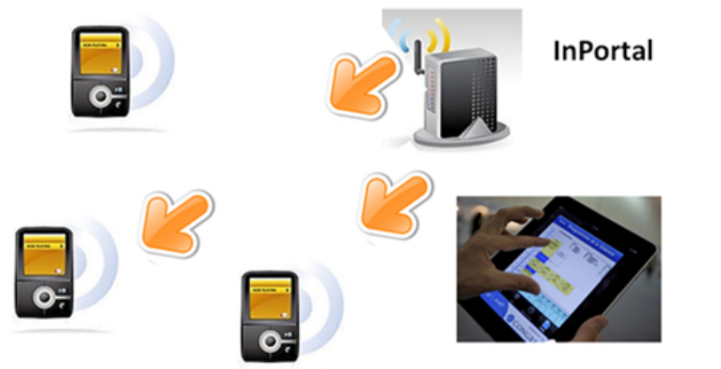
4.ApplicationScenarios
PlaceonabusoneInhandIPortal3000server,usingWIFIwirelesscoverageinsidethecar,built
3G/4GmoduletoaccesstheInternet.Passengers’smartphones,tabletandnotebooksandother
intelligentterminalaccesstotheWIFIhotspot,WIFUN1050withPortalauthenticationmethod
pushspecifiedpagetothemobileterminal,toprovideinformation,downloads,entertainment
andotherinformationservicesandInternetservices.Informationservicesavailableatthelocal
storeWIFUN1050enhanceuseraccessexperience,synchronousupdateCenterandlocalcontent
via3G/4G.
Appendix1Troubleshooting
Thismanualdescribesonlyasimpleroutertroubleshootingmethod,ifstillcannotruleout,you
cangettheservicethroughTable1‐1.
1) CannotlogonlocallyrouterthroughWebsettingpage?
useMS‐DOSPingcommandtocheckthenetworkconnection
a.Ping127.0.0.1usedtocheckthecomputermanagementTCP/IPprotocolisinstalled.
b.PingcollectiontoFEinterfaceIPaddresswhichdirectlyconnectedtorouter,usedto
checkwhethercollectionofmanagementcomputertorouter.
Numberofusersallowedtomanagetherouterhasreachedthemaximum(foruptofour
userstosimultaneouslylog),pleasetryagainlater.
PleasechecktheWebbrowserissetupaproxyserverordial‐upconnection,ifany,unset.
SeeabovePCfirewallsettingsareusedtoconfiguretherouter,whethershieldingfunction.
PleasecheckwhetherIEisequippedwiththird‐partyplug‐ins(eg:3721,IEpartner,etc.)itis
recommendedtoconfigureafteruninstalling.
2) WIFUN1050ispoweredon,butcannotaccessInternet?
Pleasecheck:
WhethertheWIFUN1050isinsertedwithaSIMcard.
WhethertheSIMcardisenabledwithdataservice,whethertheserviceoftheSIMcardis
suspendedbecauseofanoverduecharge.
Whetherthedialupparameters,e.g.APN,dialupnumber,account,andpasswordare
correctlyconfigured.
WhethertheIPAddressofyourcomputeristhesamesubnetwithWIFUN1050andthe
gatewayaddressisWIFUN1050LANaddress.
3) LANusersdroppedcable,cannotaccesstheInternet?
Checkswitchcablecollectedtorouter,andWANportnetworkcable,ifthereisloosening.
Logintotherouter'sWebsetuppage,checkaccesscontrollist,tocheckwhethertheIP
addressofasegmentisnotallowedtoaccesstheInternet.
4) WIFUN1050ispoweredon,haveapingtodetectWIFUN1050fromyourPCandfindpacket
loss?
Pleasecheckifthenetworkcrossovercableisingoodcondition.
5) ForgetthesettingafterrevisingIPaddressandcannotconfigureWIFUN1050?
Method1:connectWIFUN1050withserialcable,configureitthroughconsoleport.
Method2:WIFUN1050ispoweredon,pressandholdRESETResetbutton(untilERRORlights),
releasetheRESETbutton(ERRORlampisoff),pressandholdtheRESETbuttonagain(untilthe
ERRORindicatorblinks),andyoucanrestorethefactorydefaultsettings.
Afterapplyingtheabovetwomethods,configuretheWIFUN1050.
6) AfterWIFUN1050ispoweredon,itfrequentlyautorestarts.Whydoesthishappen?
Pleasecheck:
Whetherthemoduleworksnormally.
WhethertheWIFUN1050risinsertedwithaSIMcard.
WhethertheSIMcardisenabledwithdataservice,whethertheserviceoftheSIMcardis
suspendedbecauseofanoverduecharge.
Whetherthedialupparameters,e.g.APN,dialupnumber,account,andpasswordare
correctlyconfigured.
Whetherthesignalisnormal.
Whetherthepowersupplyvoltageisnormal.
7) WIFUN1050ispoweredon,butthePowerLEDisnoton?
Pleasecheck:
Checkthefuseisburnedout.
Checksupplyvoltage,andthepolarityisconnectedcorrectly.
8) WIFUN1050ispoweredon,connectedtothePC,WhyEthernetportlightisnoton?
Pleasecheck:
Checkthenetworkcableisnormal.
NICcharacteristiconthePCissetto10/100M,fullduplex.
9) WIFUN1050ispoweredon,whenconnectedwithPC,theNetworkLEDisnormalbut
cannothaveapingdetectiontotheWIFUN1050?
CheckiftheIPAddressofthePCandWIFUN1050areinthesamenetworksegmentand
WIFUN1050IPasgatewayaddress.
10) WIFUN1050dialupalwaysfails,Icannotfindoutwhy?

PleaserestoreWIFUN1050tofactorydefaultsettingsandconfiguretheparametersagain.
Table1‐1SalesService
TroubleDescriptionObtainservice
Hardware
failure
Forexample:WIFUN1050doesnotappear
normalpower,didnotplugthenetworkcable
whileEthernetportlightwaslitandother
issues.
PleasecontactInhand
TechnicialSupportHotline
forhelp:010‐64391099
Software
Prolem
Forexample:WIFUN1050featureisunavailable,
abnormalorconfigurationadvice.
PleasecontactInhand
TechnicialSupportHotline
forhelp:010‐64391099

Appendix2InstructionofCommandLine
OperatingstatusLED:
POWERSTATUSWARNERROR
Description
Thepower
LED(red)
StatusLED
(green)
AlarmLED
(yellow)
Error
LED(red)
onononoffPowerstatus
onblinkonoffPowerSuccess
onblinkblinkoffDialing
onblinkoffoffDialingSuccess
onblinkblinkblinkBeingupgraded
onblinkonblinkResetSuccess
SignalStatusLEDandDescription:
Signal
Status
GreenLED1
Signal
Status
GreenLED2
Signal
Status
GreenLED3
Description
offoffoffNosignalwasdetected
onoffoff
1‐9signalcondition(inthiscasesignalconditions
describeproblems,pleasechecktheantennais
installedintact,thesignalsituationintheregionis
good)
ononoff
10‐19signalcondition(inthiscaseillustratesignal
statusisnormal,WIFUN1050canbeusednormally)
ononon
20‐31signalcondition(inthiscaseillustratethe
signalingoodcondition)
EthernetPortStatusLEDandDescription:
GreenLEDDescription
onThenetworkportis100M,inanormalstate,nodatatransmission
blinkThenetworkportis100M,inanormalstate,indatatransmission
offNoconnection
MODEMLEDandDescription

MODEMGreenLEDDescription
onAlreadydialed
blinkNotdailed
POWERLEDandDescription
POWERRedLEDDescription
onNomalpowerconnection
offNopowerconnection
WLANLEDandDescription
WLANGreenLEDDescription
onWLANonfunction
offWLANofffunction
FCCSTATEMENT
1.ThisdevicecomplieswithPart15oftheFCCRules.Operationissubjecttothefollowingtwo
conditions:
(1)Thisdevicemaynotcauseharmfulinterference.
(2)Thisdevicemustacceptanyinterferencereceived,includinginterferencethatmaycause
undesiredoperation.
2.Changesormodificationsnotexpresslyapprovedbythepartyresponsibleforcompliance
couldvoidtheuser'sauthoritytooperatetheequipment.
NOTE:ThisequipmenthasbeentestedandfoundtocomplywiththelimitsforaClassBdigital
device,pursuanttoPart15oftheFCCRules.Theselimitsaredesignedtoprovidereasonable
protectionagainstharmfulinterferenceinaresidentialinstallation.
Thisequipmentgeneratesusesandcanradiateradiofrequencyenergyand,ifnotinstalledand
usedinaccordancewiththeinstructions,maycauseharmfulinterferencetoradio
communications.However,thereisnoguaranteethatinterferencewillnotoccurinaparticular
installation.Ifthisequipmentdoescauseharmfulinterferencetoradioortelevisionreception,
whichcanbedeterminedbyturningtheequipmentoffandon,theuserisencouragedtotryto
correcttheinterferencebyoneormoreofthefollowingmeasures:
Reorientorrelocatethereceivingantenna.
Increasetheseparationbetweentheequipmentandreceiver.
Connecttheequipmentintoanoutletonacircuitdifferentfromthattowhichthereceiveris
connected.
Consultthedealeroranexperiencedradio/TVtechnicianforhelp.

UnitedBusTechnology
778BlanchardWay,Sunnyvale
CA,94087‐3118
USA
T:+1‐408‐663‐4958
info@ubt.io
http://www.ubt.io/
UnitedBusTechnology
UBT(UnitedBusTechnology),asiliconvalleybasedhigh
techcompany,isfocusingonhowtoimprovebusride
experience,togeneratemorerevenueformotocoach
operators,toprovidebettermanagementforoperatorsand
tomaximizethevalueofcoachlineindustrybythepowerof
Internet+technology.Ourmissionistoprovidethebest
internet+servicetoallmotocoachoperatorswith
cutting‐edgeproductlinesthatcoversfromdailybus
businessoperationtopassengers’ridingexperience.