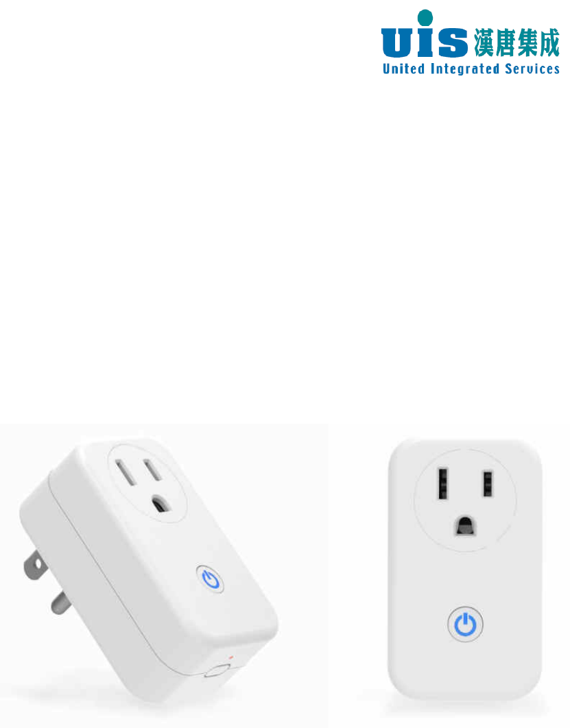
United Integrated Services WPW-220 Wireless Power Switch User Manual
United Integrated Services CO., LTD. Wireless Power Switch
User Manual
Confidential
WPW-220 Wireless Power
Switch (US)
Installation instructions
Table of Contents
一、Product Overview .......................................................................................... 1
二、Feature............................................................................................................ 1
三、Installation Operation..................................................................................... 2
四、Precautions ..................................................................................................... 2
五、Troubleshooting ............................................................................................. 3
Confidential 1
一、Product Overview
1. Product Name:Wireless Power Switch (US)
2. Model:WPW-220
3. Power supply:100~120VA C
4. Dimensions (mm) and Accessories:82 x 45x 36mm The controller
base, manual
二、Feature
1. Radio transmission, sent to the receiving host on / off signals to
control the power supply or power outlet execution, also by phone to
remotely control home electrical equipment, improve convenience of
life.
2. Series compatible, can be used with wireless door detector (SCT-230)
or wireless displacement detector (SMT-230) do not even move
control, such as corridors auxiliary lighting at night.
3. Easy to use, placed in a power outlet, press the SET button, so that
the host is connected to each other to complete the setup.
4. It can be connected to other appliances. Transparent LED keys to
control the power state, the red light indicates that the power output.
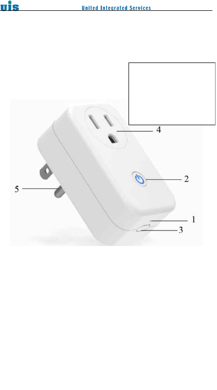
1. Setting LED status
2. Button (with warning
lights)
3. (SET) set key
4. 3-point power outlet
5. 3-point power plug

2
5. Both wireless signal router functions, transmission system may
extend the terminal host and detector distance.
三、Installation Operation
1. First WPW-220 connected to the power outlet, then will enter the boot
mode, the blue light on the front of the boot will be completed after
about 90 seconds of constant light. If you want to skip this program,
press the SET button.
2. To register the first to prepare the upper device - Press Gateway
(Host) or short press Router (router) behind the SET button, then
press the SET button on the side of the machine. In this case the host
device and this opportunity within about 15 seconds flashing lights;
when the connection is successful, the host device and the machine's
LED light will flash at the same time long after the close, that has
successfully paired connection.
3. If the connection fails, the second party device will flash after 15
seconds in length at the blue lights.
4. Transparent front LED button to control the power state, blue light
indicates power output.
5. Power Measurement: When I want to measure the electrical
connector socket on the machine, turn the power output starts
automatically calculate the voltage, current, power. (Need to use
power measurement value for at least one hour)
6. Price calculation: please set by the web user interface peak, off-peak
electricity price and time, and set the time of desire accumulated (in
months, up to three months), the system automatically calculates the
total price, and to distinguish between peak, off-peak electricity (as far
back in 1 year)
7. Power measured values via web, mobile APP, wireless terminal
controller made, APP achieved price calculated values via web,
phone.
8. Releasing the connection: Press the sides of the machine SET button
until flashing green light goes out and then release, the unit for about
three seconds after the long flashed blue lights, that means lifting
successful connection.
四、Precautions
1. The maximum current load of 10A / 120V, 1200W
3
2. Power measurement ranges:
(1) Measuring voltage range:100~130VA C
(2) Measuring Current Range:0.3~10A
(3) Measuring power range:30~1300W
(4) Measuring the cumulative time in months, up to three months (as far
back in 1 year)
3. As the wireless signal router can connect up to 16 wireless detectors.
1 set of system can accommodate up to 16 wireless signal router.
4. Wireless signals in series to host up to three relay.
五、Troubleshooting
1. Abnormal situation: WPW-220 LED indicator flashes the number of
abnormal, can not recognize the connection status. Treatment:
a. Make sure the power outlet is connected properly and whether
the power supply is normal supply.
b. Re-plug power, restore factory value, and set the connection
again.
c. If the above situation to handle invalid, please contact your
dealer.
2. Abnormal situation: unable to connect with the wireless host.
Treatment:
Make sure the distance WPW-220 and the host or between repeaters,
whether in unsheltered effective distance of 300 meters straight. If the
shelter will shorten the effective distance, you can shorten the
distance between the two, or join repeaters, re-test without
improvement.
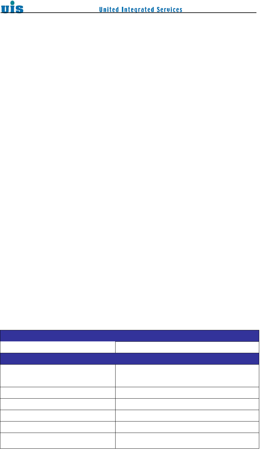
Specifications
UIS/Wireless Power Switch
Model No. WPW-220
Electrical Specification
Transmit Frequency 2.4GHz ISM band, IEEE802.15.4: 2405 ~
2480MHz
Channel NO. 16 Channel (2405MHz to 2480MHz)
Operation Range Up to 200 meters (LOS)
RF Nominal output power 15 ± 1 dBm
RF Receiver sensitivity -97 dBm(typ)
Power Consumption Working: ~1.87W
4
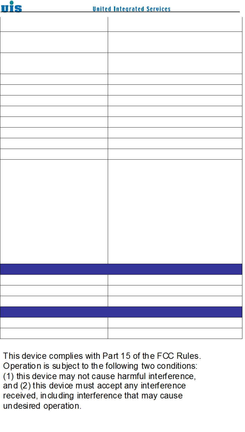
Standby: ~1.32W
LED Indicator Blue 1PC/Red 1PC
LED Status: Relay (ON/OFF)
Operation Interface Push button switch for setting on the side
Push button switch for Relay on/off in front
Operating Voltage 100~120VAC 50/60 Hz
Resistive Load 10A/120VAC, 1200W max.
Inductive Load (Single Face) 0.5HP/120VAC
Over Current Protection 11A
Measure Voltage Range 100~130VAC
Measure Current Range 0.3A~10A± 10%
Measure Power Range 30~1300W± 10%
Software Protocol Version ZHA1.2x
Reconnect scenario
Reconnect scenario will be implement when
device in ORPHAN state
STEP 1 : Reconnect to original network 3
times every 5min. If not success, enter
STEP-2
STEP 2 : Reconnect to original network 3
times every 30min. If not success, enter
STEP-3
STEP 3 : Reconnect to original network every
60min repeatedly.
Environmental Requirement
Operating Temperature -10°C to 50°C
Storage Temperature -10°C to 70°C
Humidity 90% RH Max., Non-Condensing
Mechanical Specification
Dimension (WxHxD, mm) 82 x 45x 36
Weight 70g

5
Notice : The changes or modifications not expressly approved by the party
responsible for compliance could void the user’s authority to operate the equipment.
IMPORTANT NOTE: To comply with the FCC RF exposure compliance
requirements, the antenna(s) used for this transmitter must be installed to provide a
separation distance of at least 20 cm from all persons and must not be co-located or
operating in conjunction with any other antenna or transmitter. No change to the
antenna or the device is permitted. Any change to the antenna or the device could
result in the device exceeding the RF exposure requirements and void user’s
authority to operate the device.
低功率電波輻射性電機管理辦法
第十二條
經型式認證合格之低功率射頻電機,非經許可,公司、商號或使用者均不得
擅自變更頻率、加大功率或變更原設計之特性及功能。
第十四條
低功率射頻電機之使用不得影響飛航安全及干擾合法通信;經發現有干擾現
象時,應立即停用,並改善至無干擾時方得繼續使用。
前項合法通信,指依電信法規定作業之無線電通信。
低功率射頻電機須忍受合法通信或工業、科學及醫療用電波輻射性電機設備
之干擾。