United Integrated Services WR-110 WIRELESS REPEATER User Manual
United Integrated Services CO., LTD. WIRELESS REPEATER Users Manual
Contents
- 1. USERS MANUAL
- 2. Users Manual
Users Manual

Confidential 1
Wireless Home Security System
User Manual
Rev. 1

Confidential 2
Content
1. System Installation Guide
2. User Operation Guide
3. Troubleshooting Guide
4. Application Guide

Confidential 3
WR-110
PC/HTTP Console Configuration Guide
Confidential 4
WR-110
WR-110
WTS-110
WCS-110
WPC-110
WMS-110
WAC-110
WSS-110
PC Console
3G Mobile
Cellular Station
IP Camera
WDT-110
WAT-110
WLC-110
3’rd-party
Smoke Sensor
3’rd-party
Electronic Door
Locker
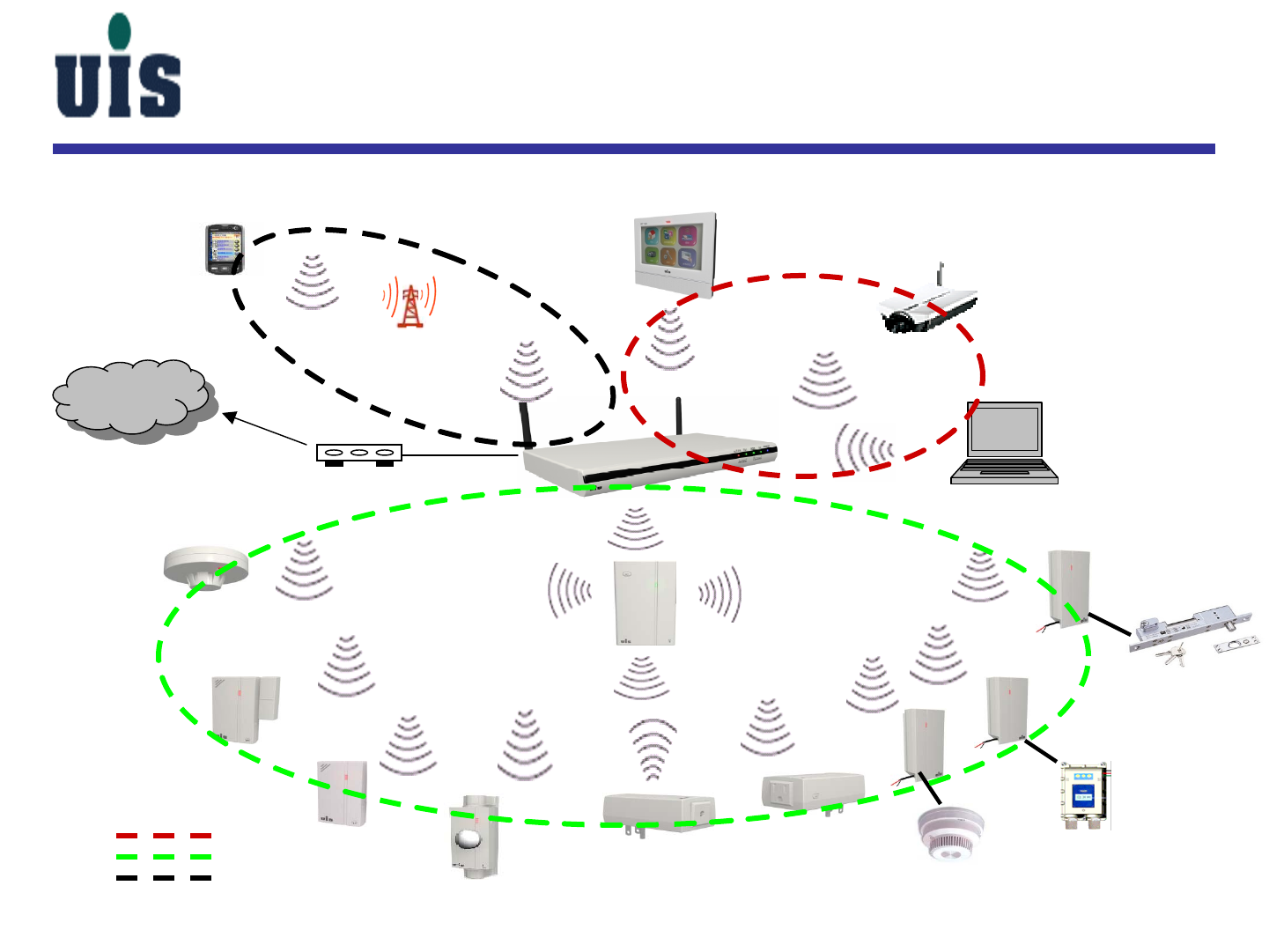
System Architecture
3’rd-party
CO detector
WCC-110
3G WiFi WiFi
WiFi
Zigbee
Zigbee-likeZigbee-like
Zigbee-like
3G
Internet
CPE(CM or ATU-R) Ethernet
WiFi
Zigbee
3G
Confidential 5
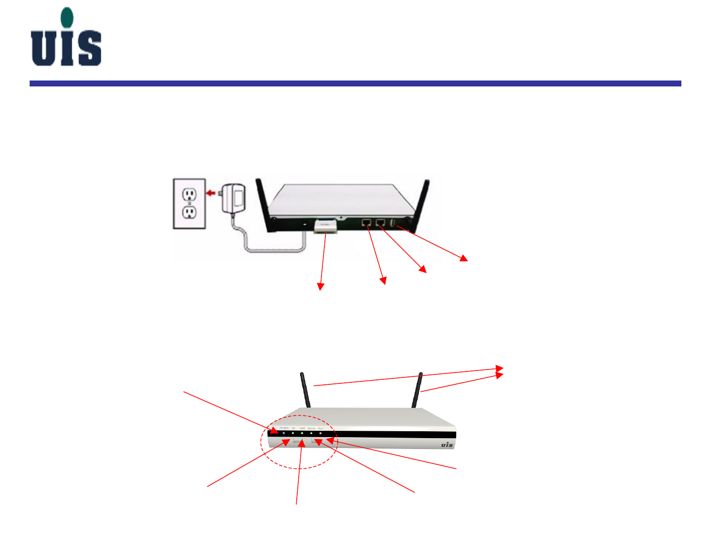
DC 12V IN
WR-110
Step 1:Power on the Gateway(WR-110) - plug adapter into the wall
power socket
Step 2:It takes around 40 sec for Gateway to boot up and get ready, you
may check out the LEDs of Power(blue) / Normal(green) to identify
Power
3G
WAN Normal
Alarm
System Setup
3G express card LAN WAN
USB
Antenna
LED
Confidential 6
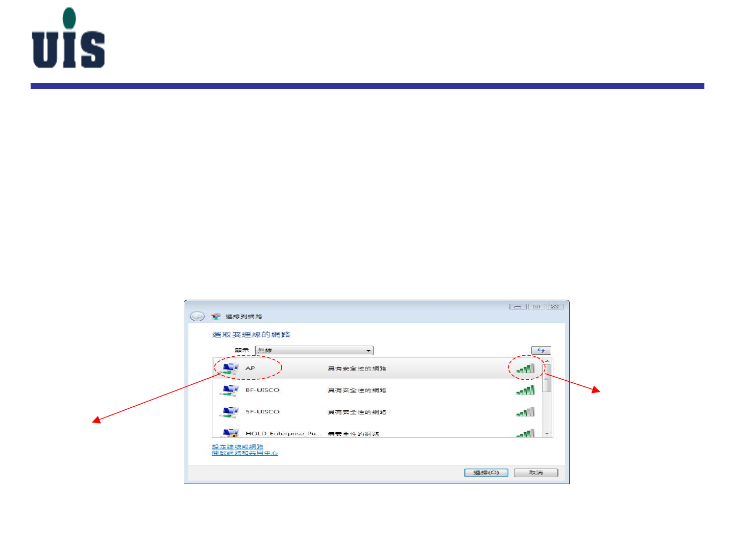
Step 3:Set up WiFi connection between the PC and Gateway
-Power on your PC and enable WiFi(only 802.11b/g supported) network
access
-Set PC’s WiFi interface IP by using DHCP(dynamic IP)
-Search Gateway’s SSID (you may see the default SSID value on the
bottom side of Gateway while doing the first time setup) and get
connected with Gateway (PC’s WLAN IP address will be assigned by
Gateway)
System Setup
SSID
WiFi signal
Confidential 7
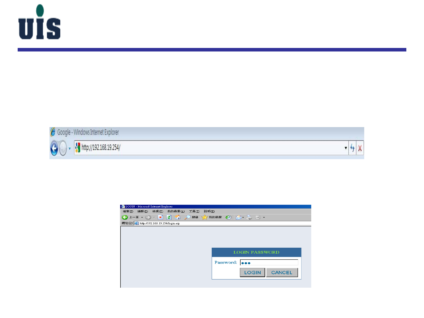
System Setup
Step 4:Set up PC console
- Open the IE browser(6.0 or above) and enter the Gateway IP (you may see
the default IP address on the bottom side of Gateway while doing the first
time setup)
- Key in the login password “123” (factory default) to enter the main page
Confidential 8
System Setup
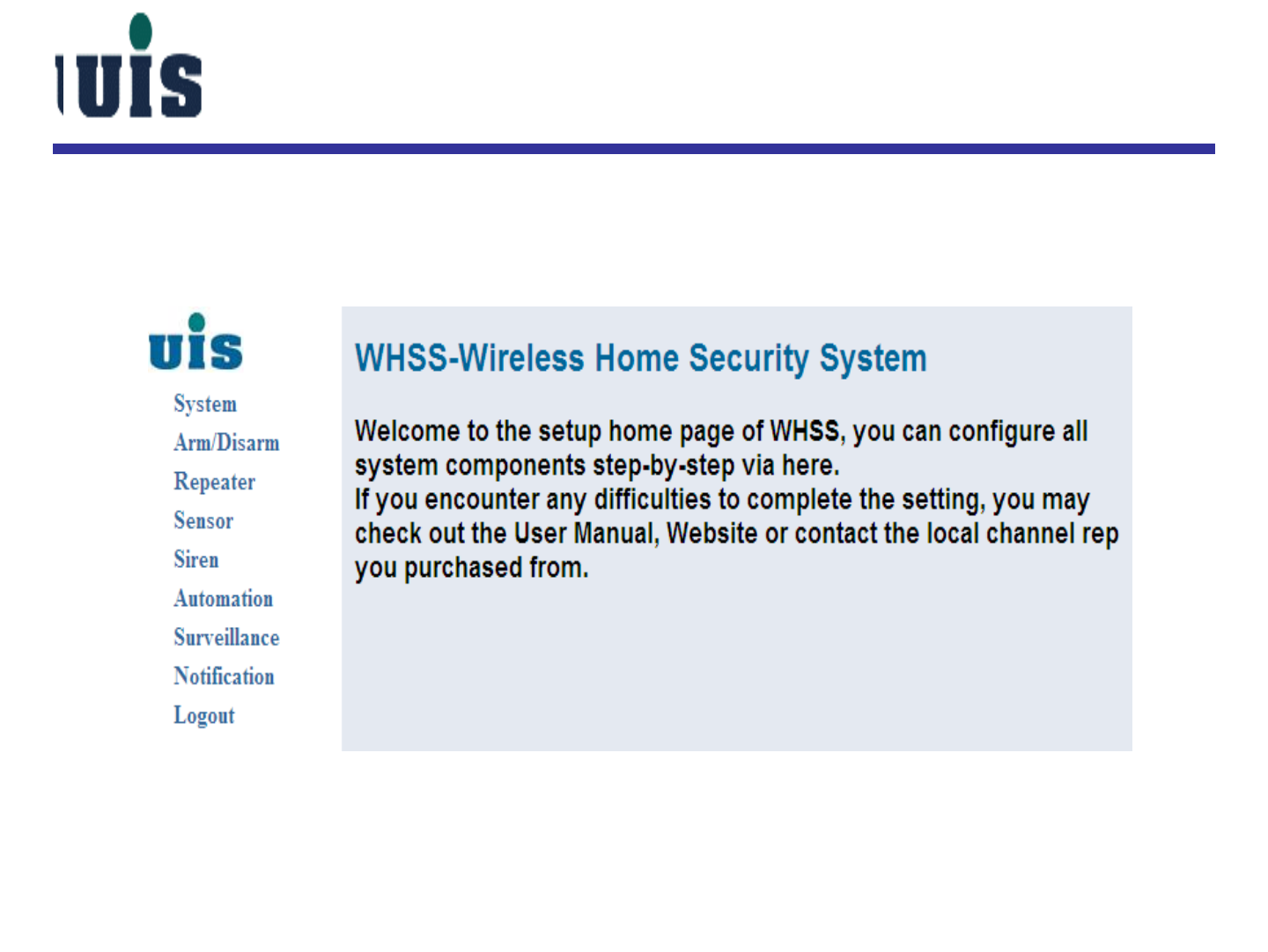
Step 5:Enter the main console of Gateway
Confidential 9
System Setup
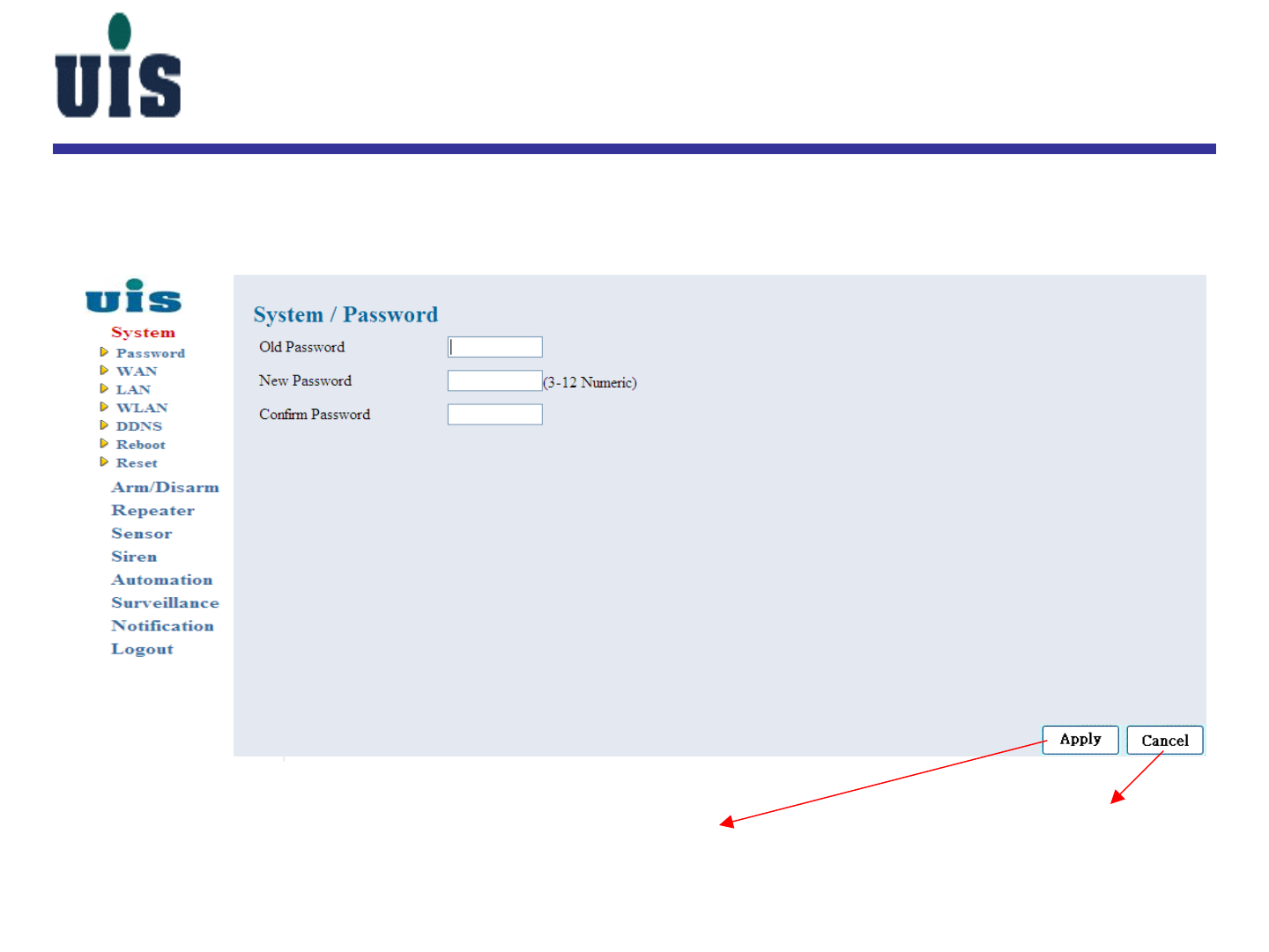
Step 6:Click “System” to change the console login password
click here to take effect click here to abort
Confidential 10
System Setup
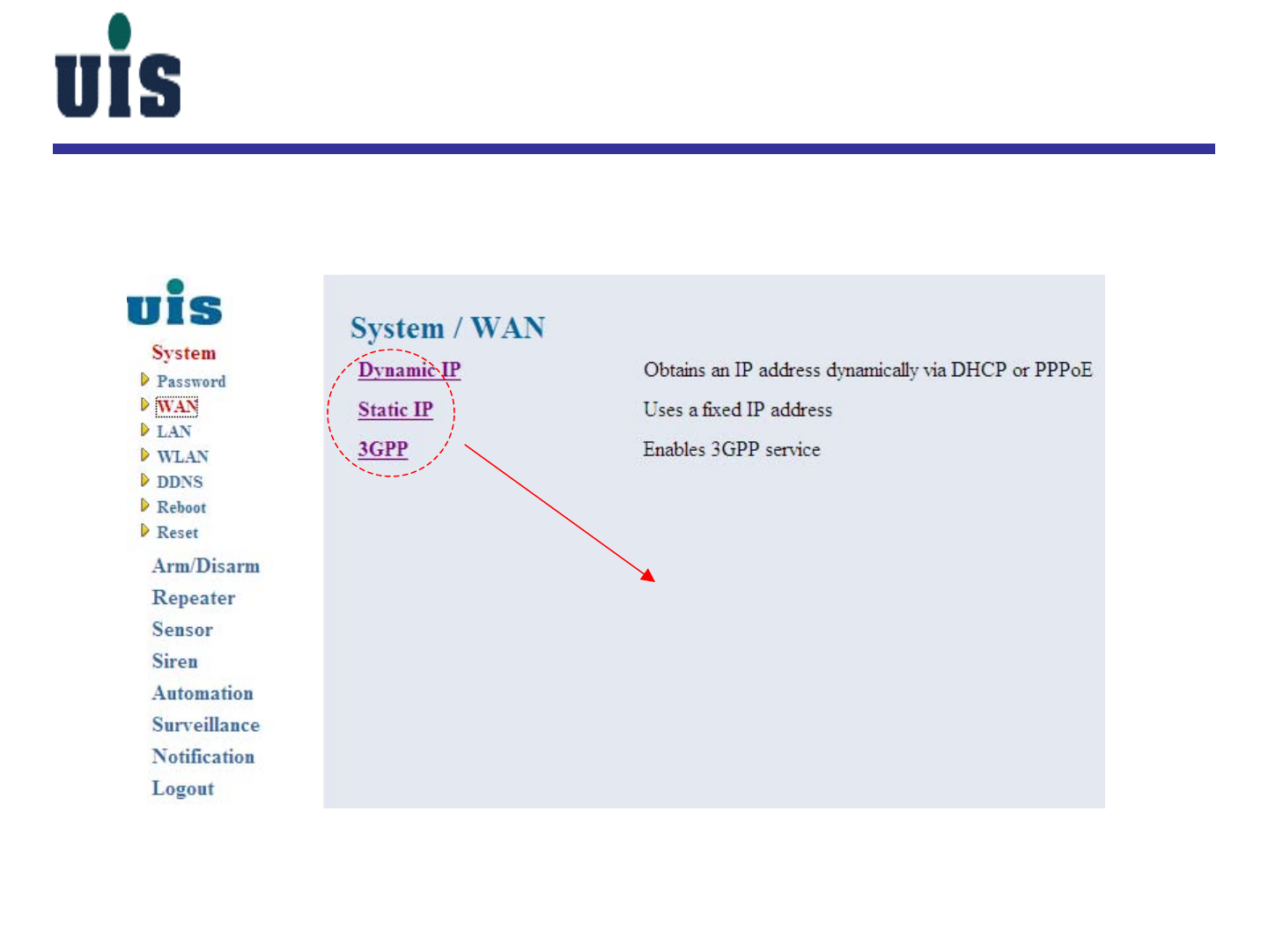
Step 7:Click “WAN” to configure Gateway’s WAN interface
choose either one to connect to Internet
(must be following up with your local ISP
OR 3G mobile operator )
Confidential 11
System Setup
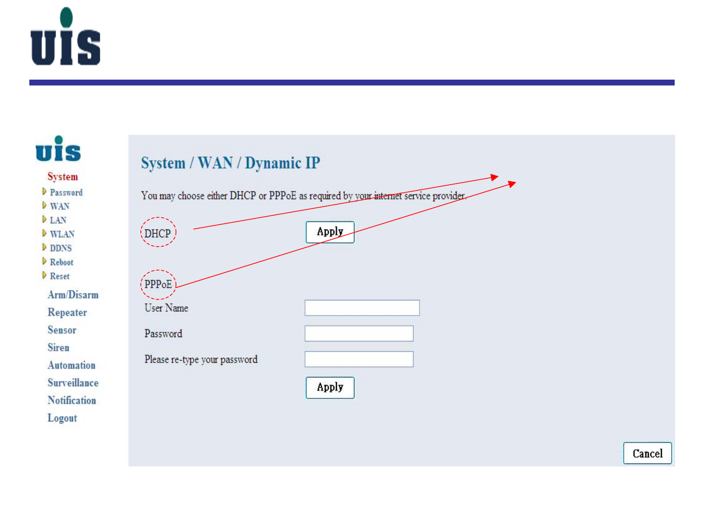
Step 8:Click “Dynamic IP” to configure Gateway’s WAN interface
choose either one as required
Confidential 12
System Setup
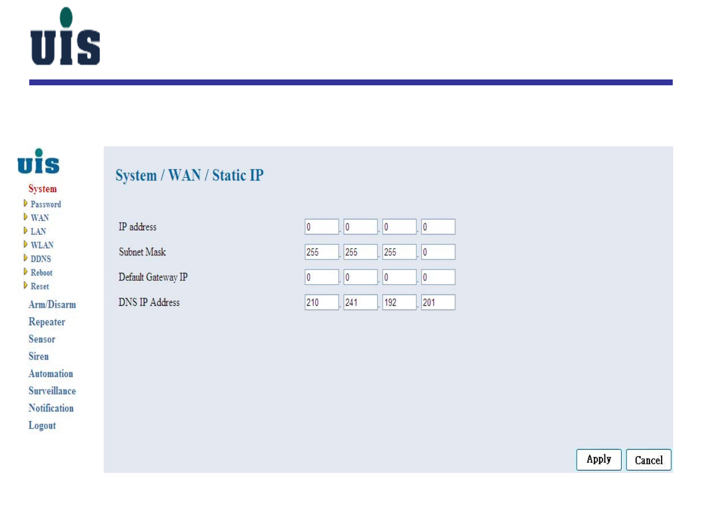
Step 9:Click “Static IP” to configure Gateway’s WAN interface
Confidential 13
System Setup
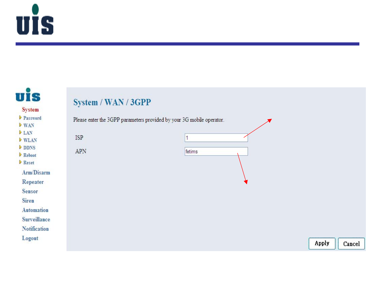
Step 10:Click “3GPP” to configure Gateway’s WAN(3G express card)
interface
user-definable
key in the value per your 3G provider
Confidential 14
System Setup
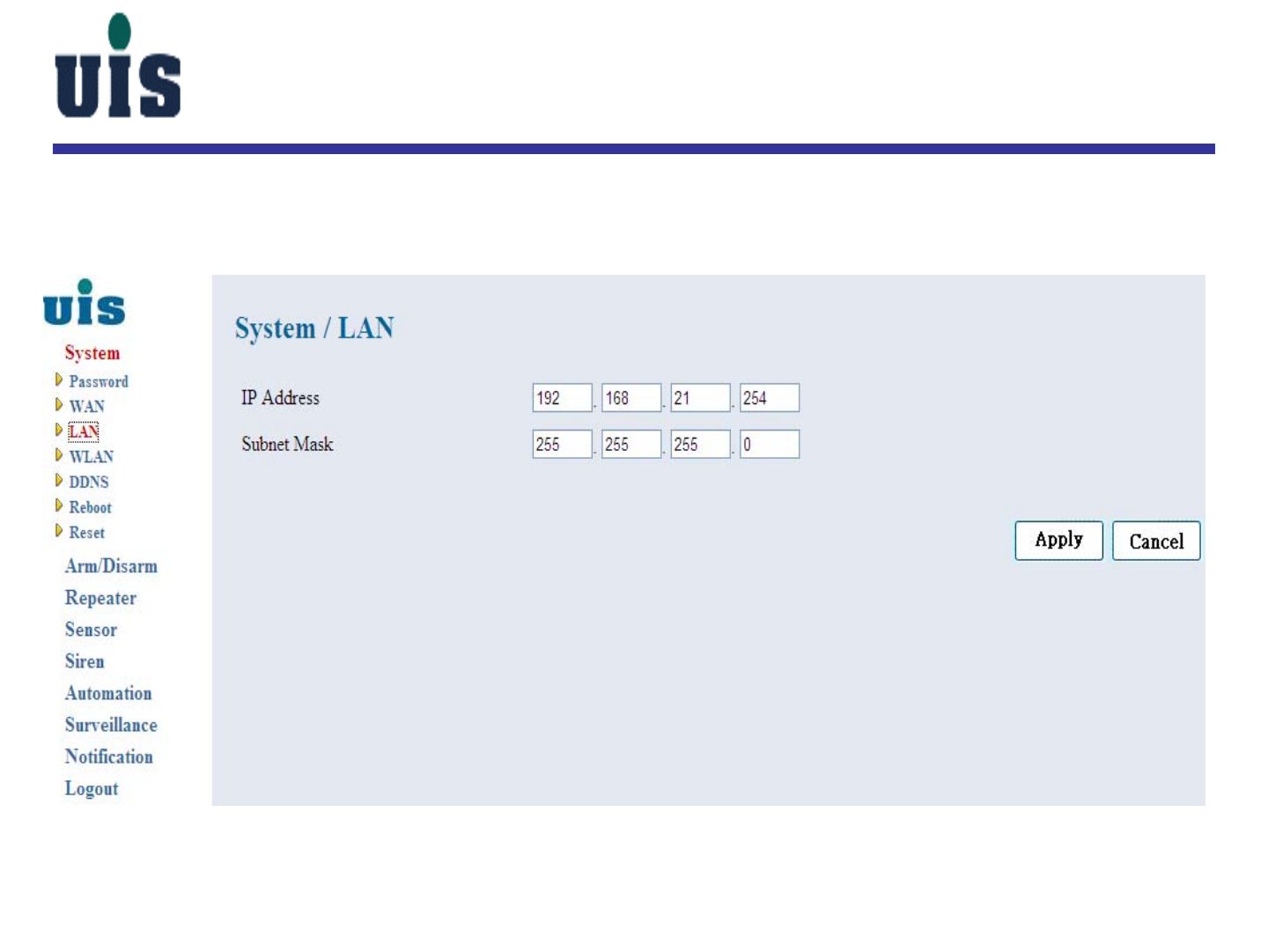
Step 11:Click “LAN” to configure Gateway’s LAN interface
Confidential 15
System Setup
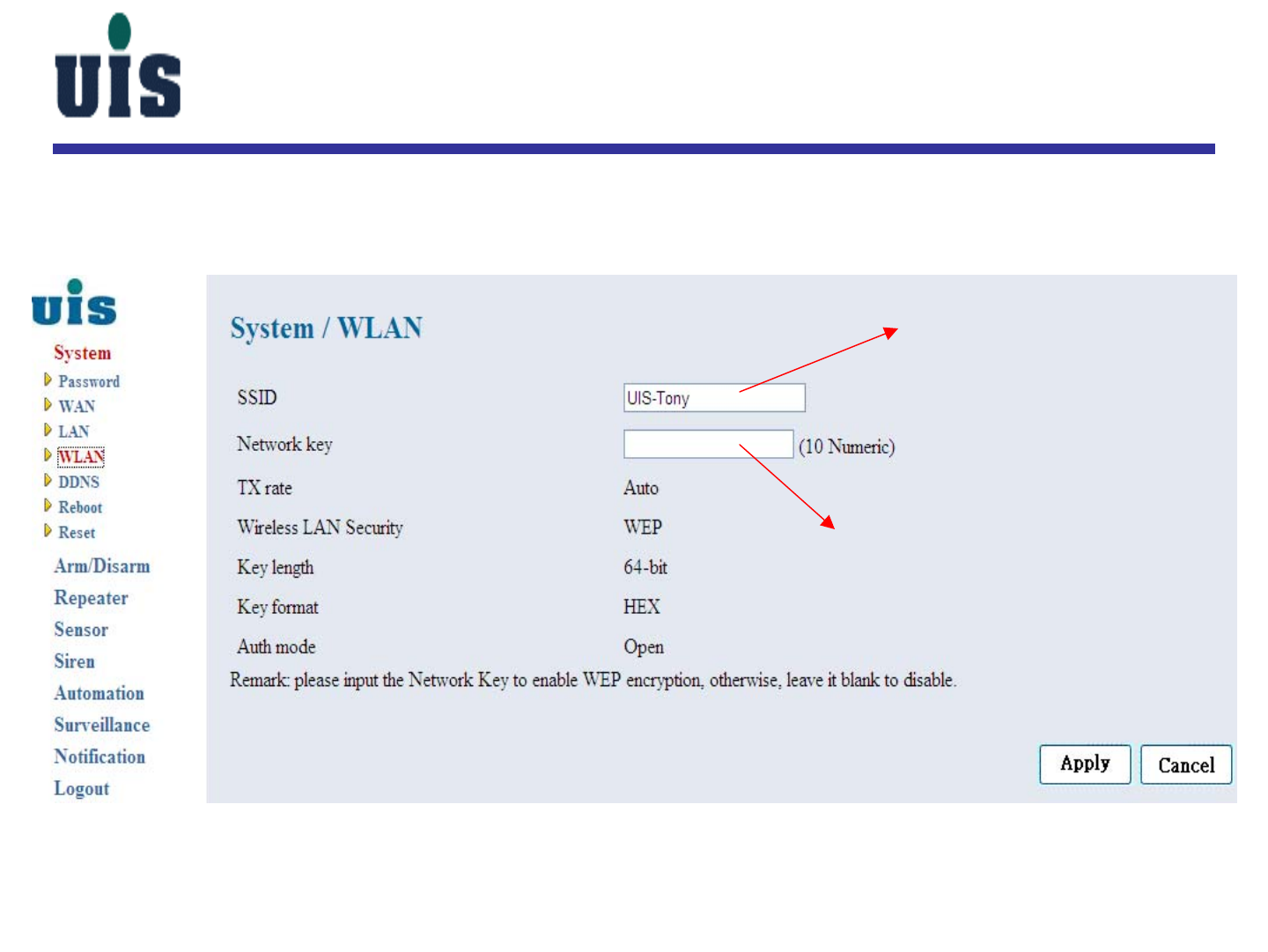
Step 12:Click “WLAN” to configure Gateway’s WLAN interface
you may change the value as
required
you may define the key to enable
WEP data encryption as required
Confidential 16
System Setup
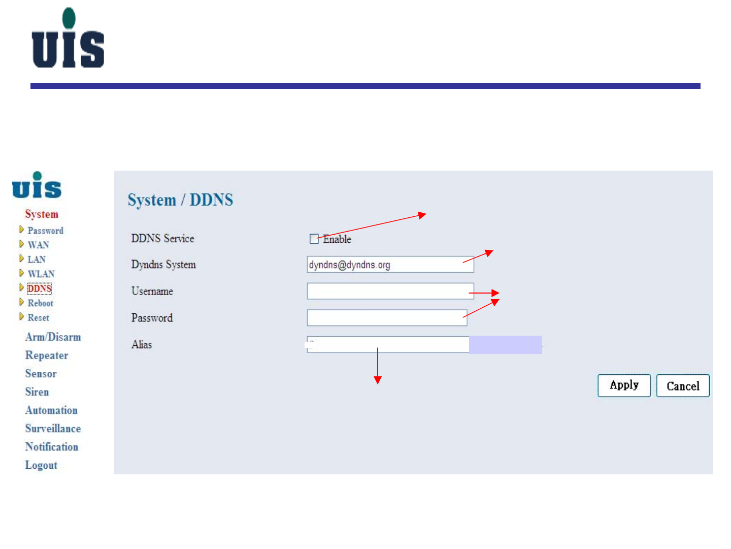
Step 13:Click “DDNS” to configure Gateway’s DDNS (Dynamic
DNS) information
click here to enable DDNS service
key in DDNS provider’s domain name
key in the value while applying
DDNS service (you may attain the
account information once done
the DDNS service registration)
key in the registered domain name
Confidential 17
System Setup
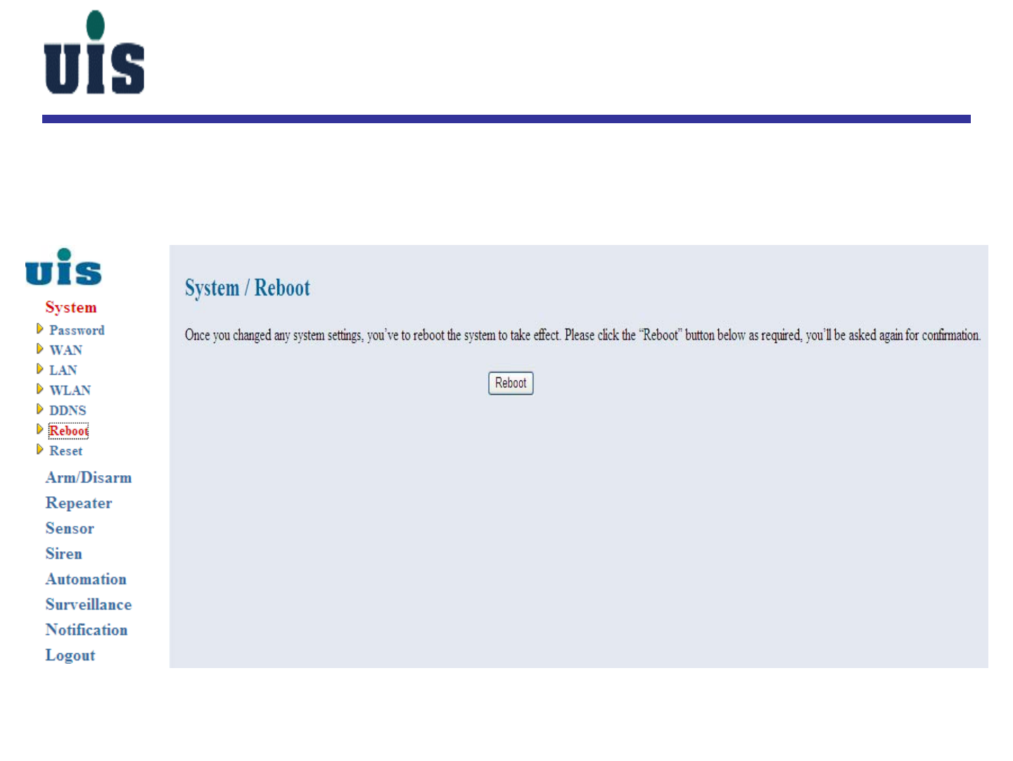
Step 14:Click “Reboot” to power reboot the Gateway
Confidential 18
System Setup
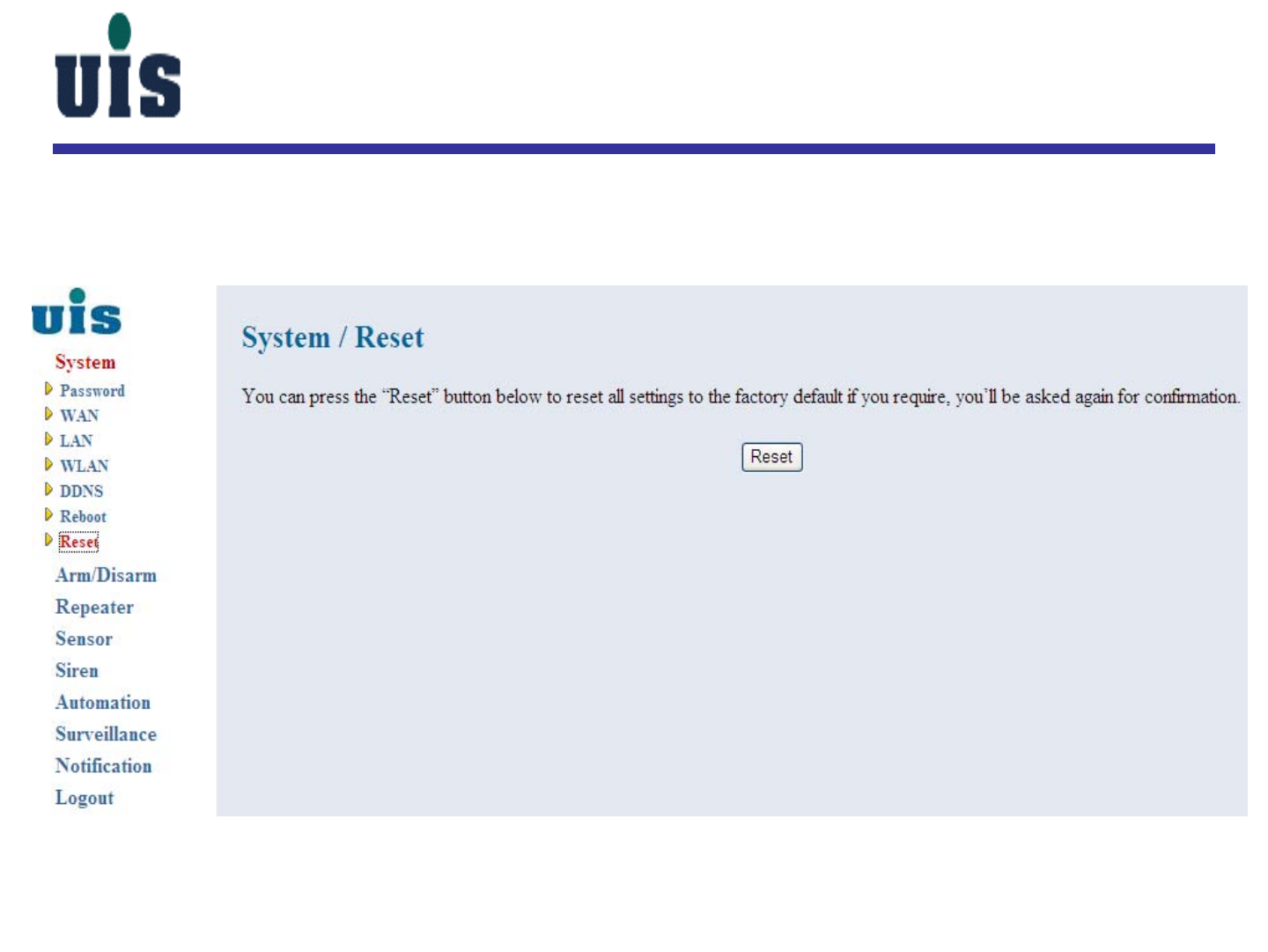
Step 15:Click “Reset” to reset all settings to the factory default and
power reboot the Gateway
Confidential 19
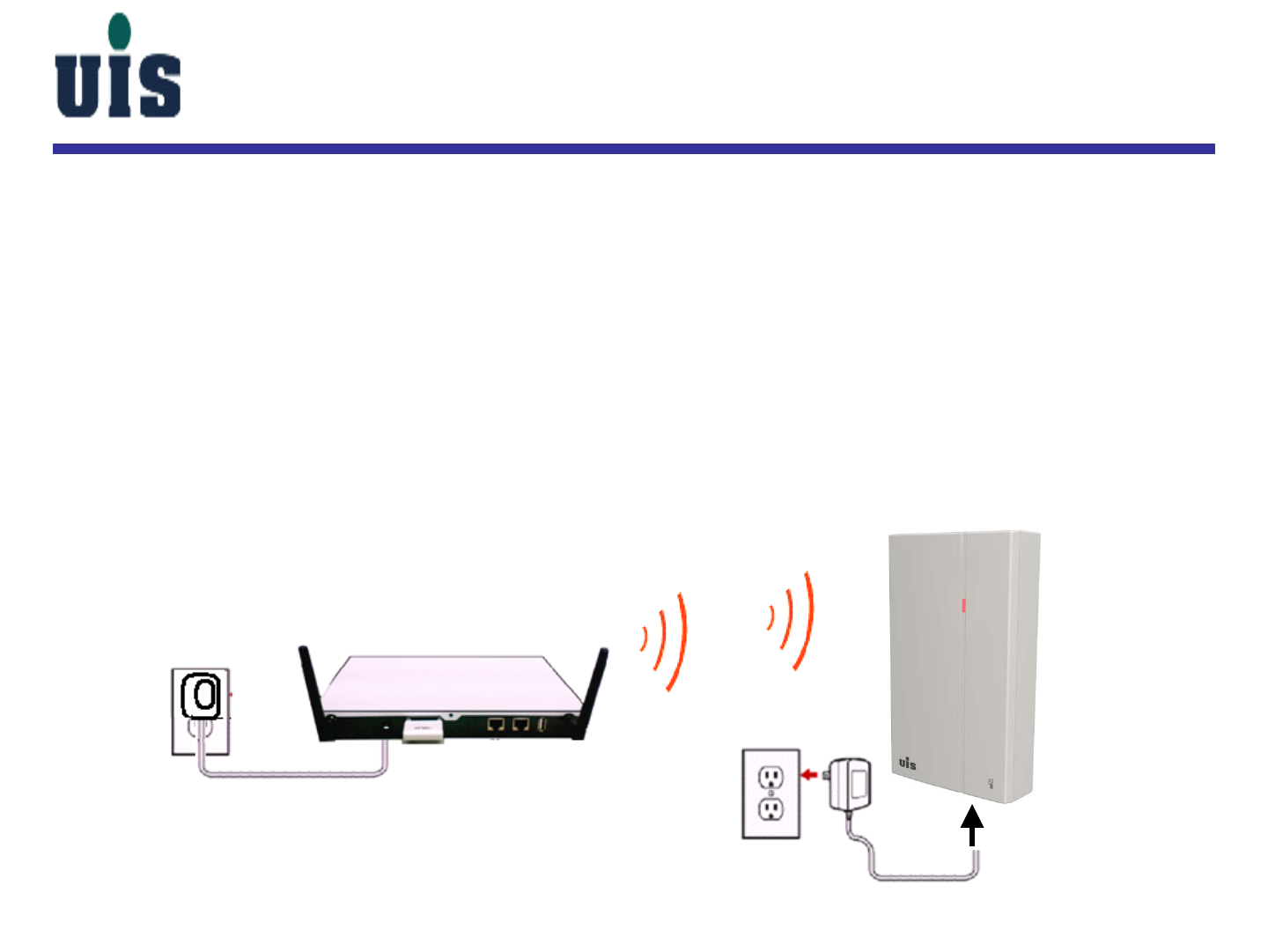
Step 16:Power on the Wireless Repeater (WR-110) and get connected
with Gateway
-Plug adapter into the wall socket to power on the Repeater
-Push the back side “set” button of Repeater for 5 sec, the indicator will
blink blue light twice and turn red light again
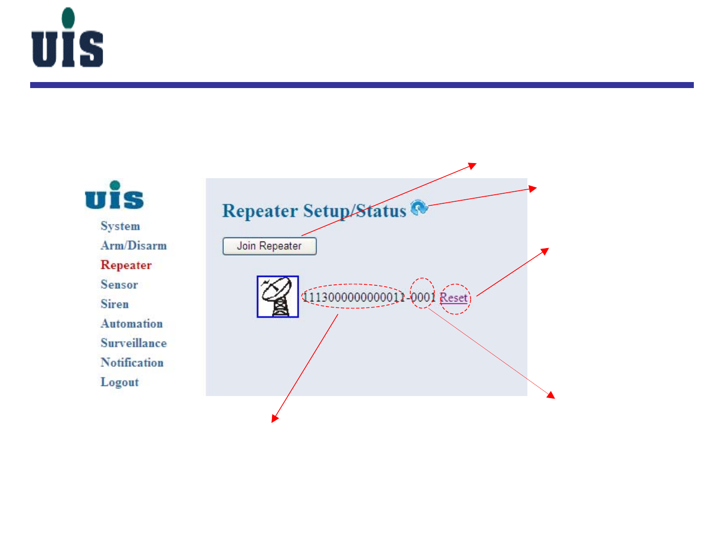
-Click “Join Repeater” button via the WR-110 console (see next page) to join the repeater
-Repeater’s indicator will turn blue light to sync up the access ID with WR-110
-Wait couple seconds or click the “Refresh” button to check out the result
-Repeat above steps to join the other repeaters
-The max. distance between Gateway and Repeater is 30M as suggested
WR-110 WR-110
Repeater Setup
Confidential 20
Repeater Setup
Step 17:Click “Repeater” to configure repeaters
you can join multiple Repeaters
thru here
the ID has to be matched (Repeater vs. Gateway)
to complete the binding
click here to clean all
binding sensor information
the unique channel #
between Repeater and
Gateway
Click here to refresh the status
Confidential 21
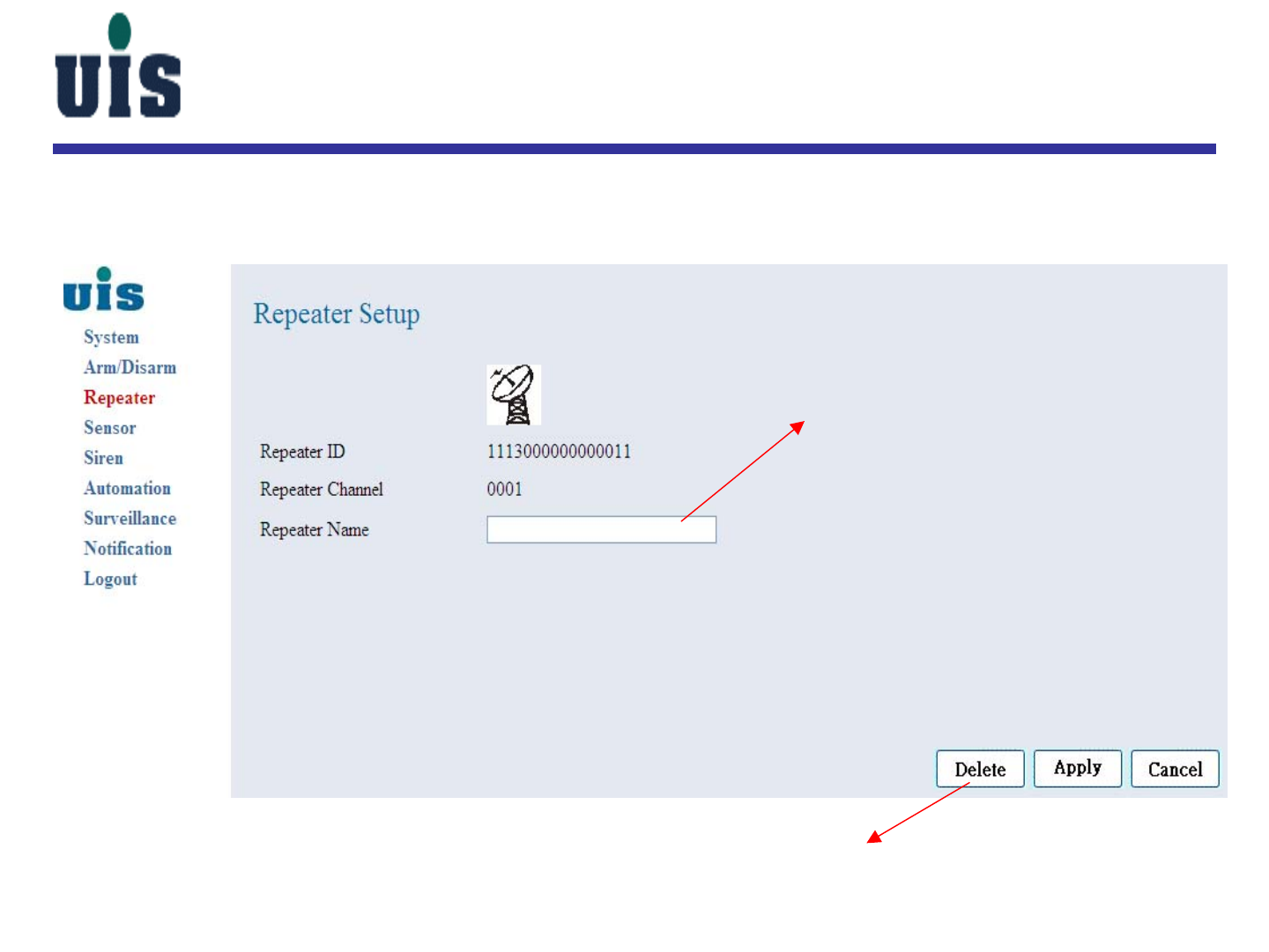
Repeater Setup
user-definable alias
click here to delete this Repeater connection
Step 18:Click the specific Repeater to configure
Confidential 22
WR-110
WCS-110
LED
LED rear side button
rear side button
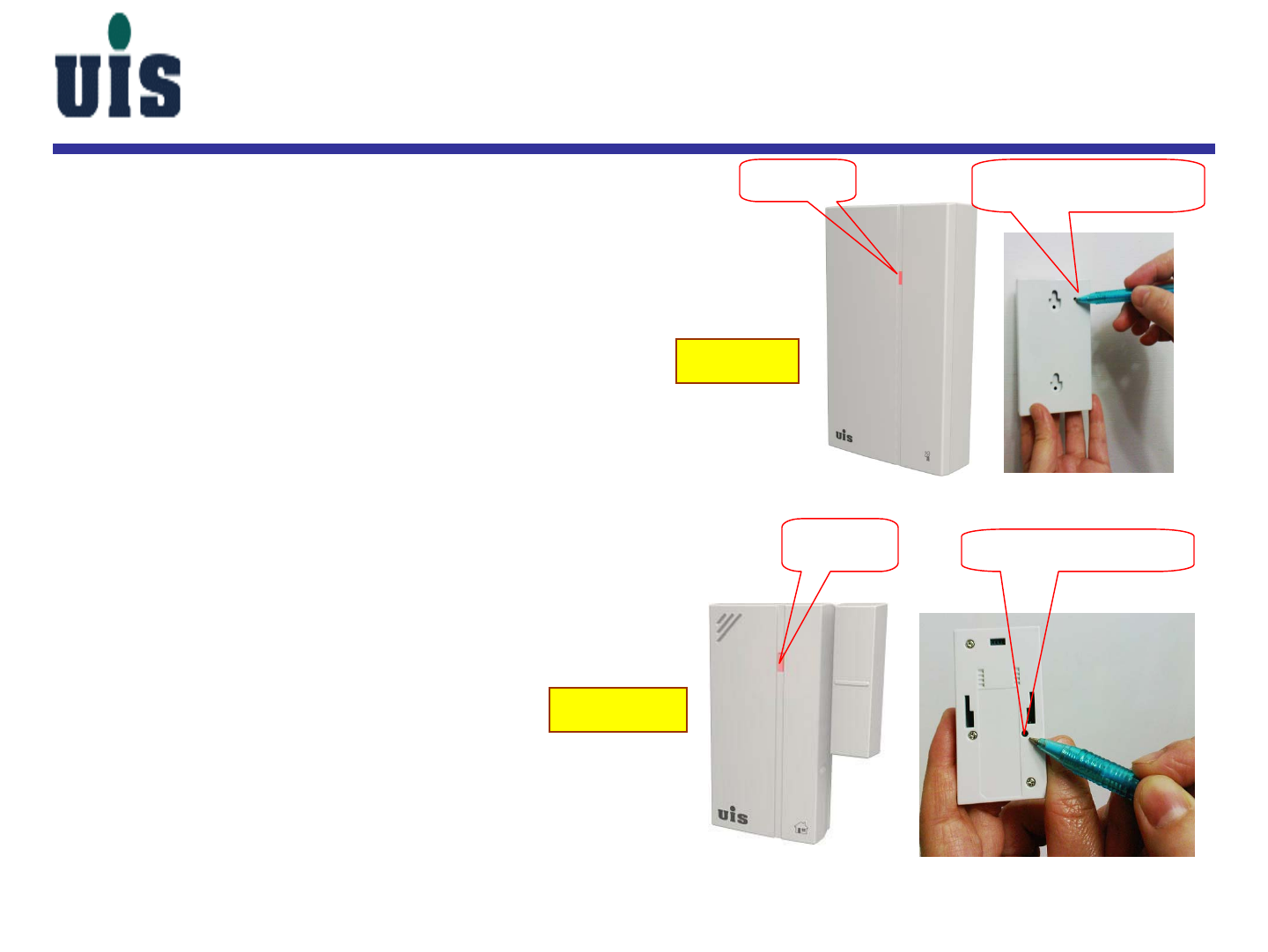
Device Binding
1. Push Repeater’s button (rear side) once
2. Push Device’s button (rear side or left side nearby logo) once
3. Verify if Device’s LED flashes three
times (red color) in sec and meanwhile,
verify if Repeater’s LED flashes once (blue color)
4. Repeat the above actions for all rest devices
Device means for:
-Sensor
-Siren
-Controller
-Transducer
Remarks:
-while binding Smoke Sensor, after pushing
the button, it will alarm three times in sec
-while binding Siren, after pushing
the button, the LED will flash three
times in around 15 sec
-the max. distance between Sensor
and Repeater is 10M as suggested
-Sensor will send status update to
Repeater automatically in every 10 minutes
-Gateway will put Sensor as “disconnected” status if
Gateway didn’t get Sensor’s keep-alive signal (via Repeater)
in 30 minutes (10 min/time x 3)
Confidential 23
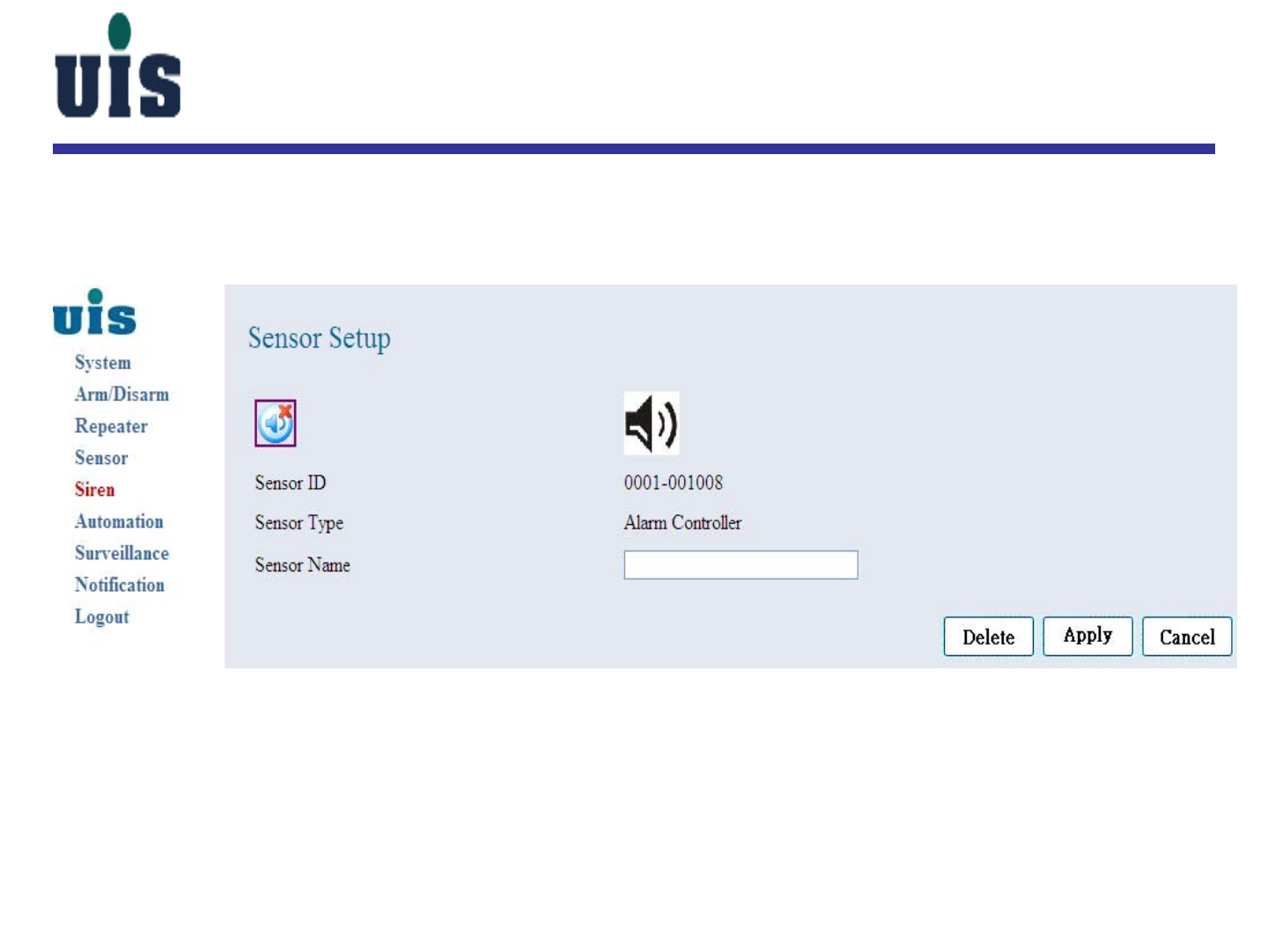
Siren Setup
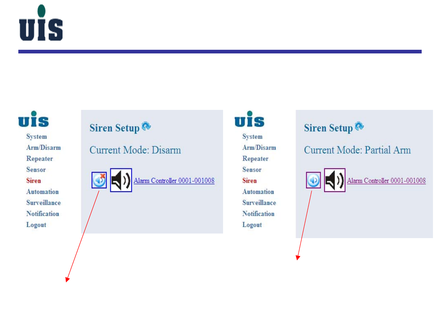
Step 19:Click “Siren” to configure sirens
silent mode
alarm mode
Confidential 24
Siren Setup
Step 20:Click the specific Siren to configure
Confidential 25
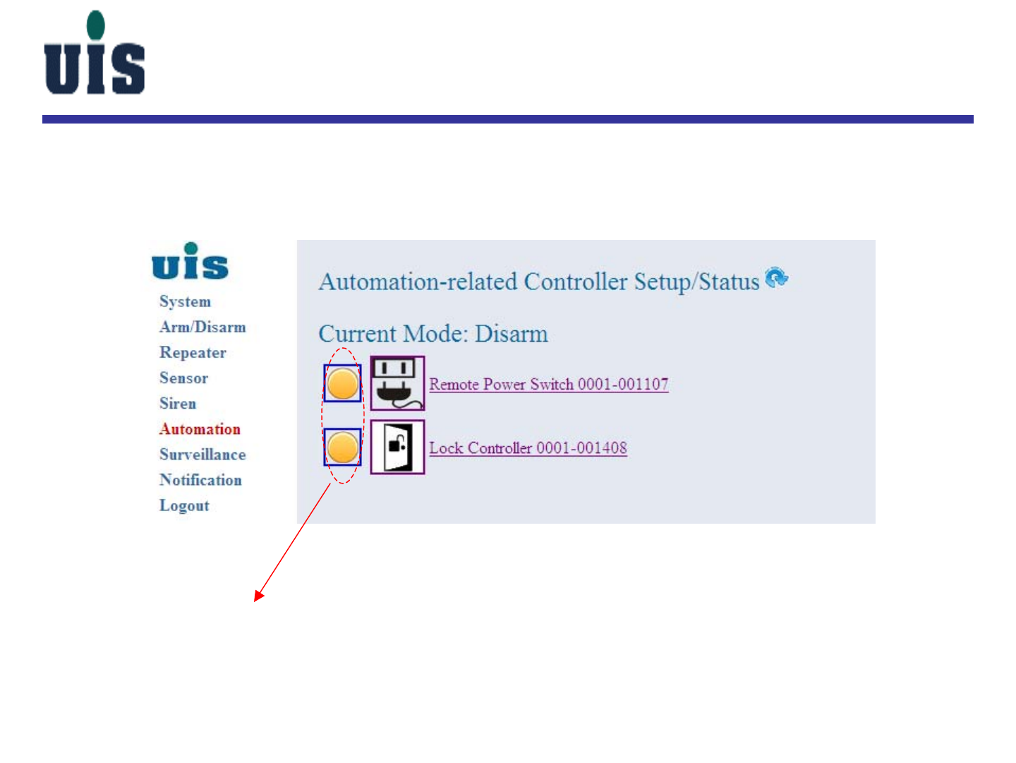
Automation Setup
Step 21:Click “Automation” to configure controllers
Orange means “turned-off”
Green means “turned-on”
Confidential 26
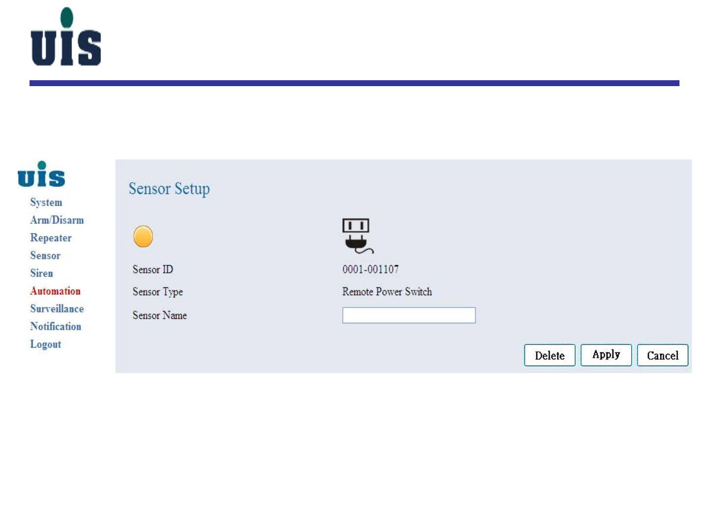
Automation Setup
Step 22:Click the specific Power Controller to configure
Confidential 27
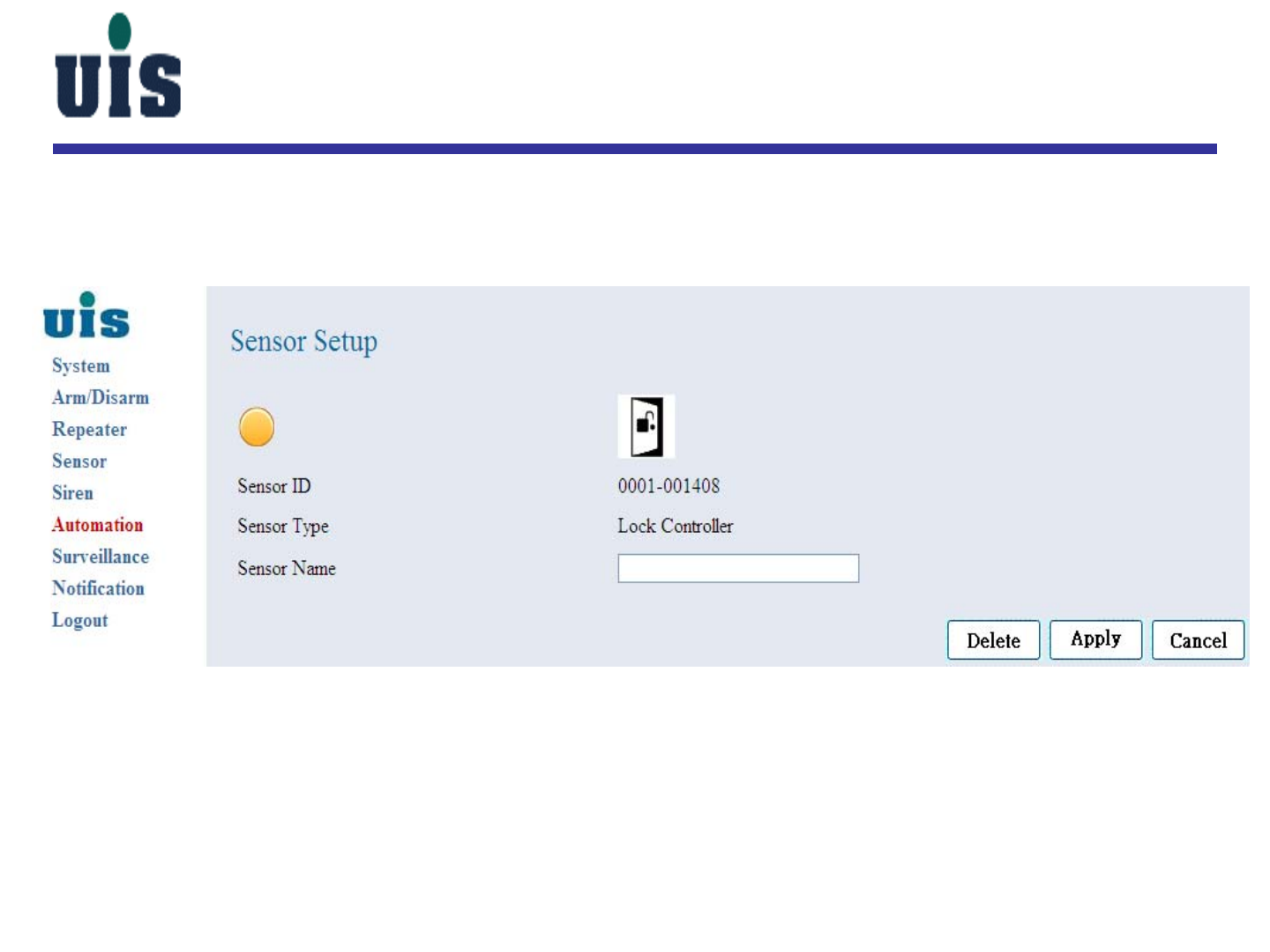
Automation Setup
Step 23:Click the specific Lock Controller to configure
Confidential 28
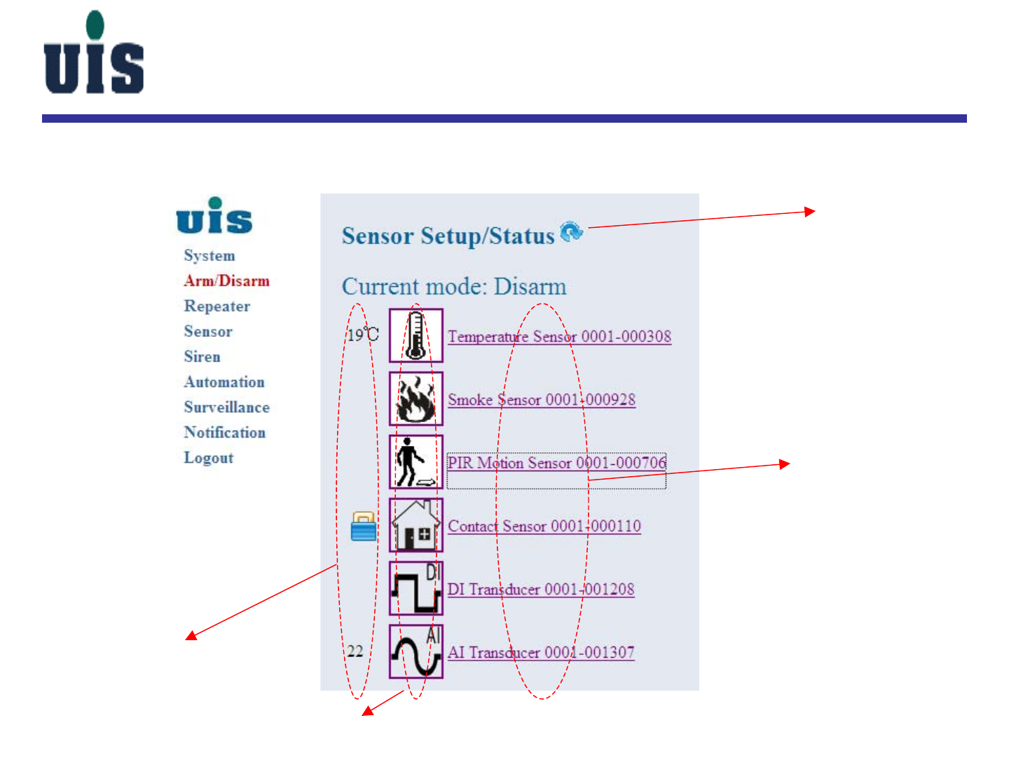
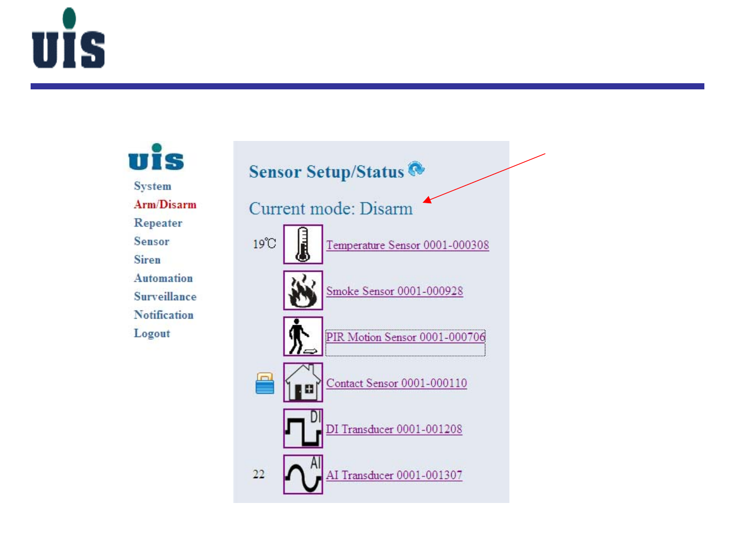
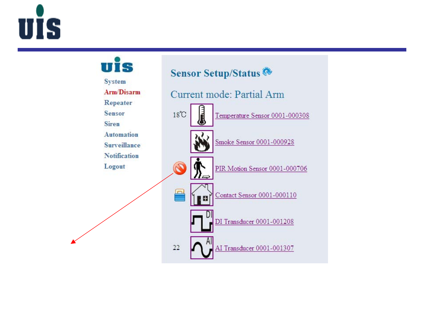
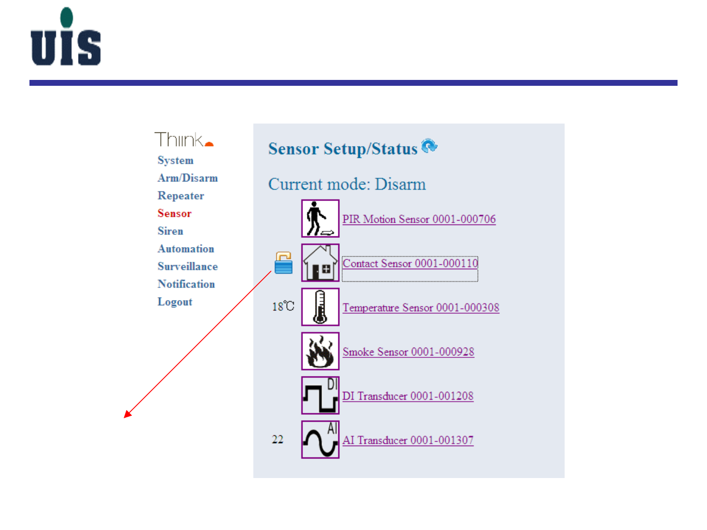
Sensor Setup
Step 24:Click “Sensor” to display all binding sensor information
sensor status or current value
sensor symbol
sensor name & id
click here to quick
refresh all sensor
status manually
Note:
•the console will be auto
refreshed in every 20 sec
Confidential 29
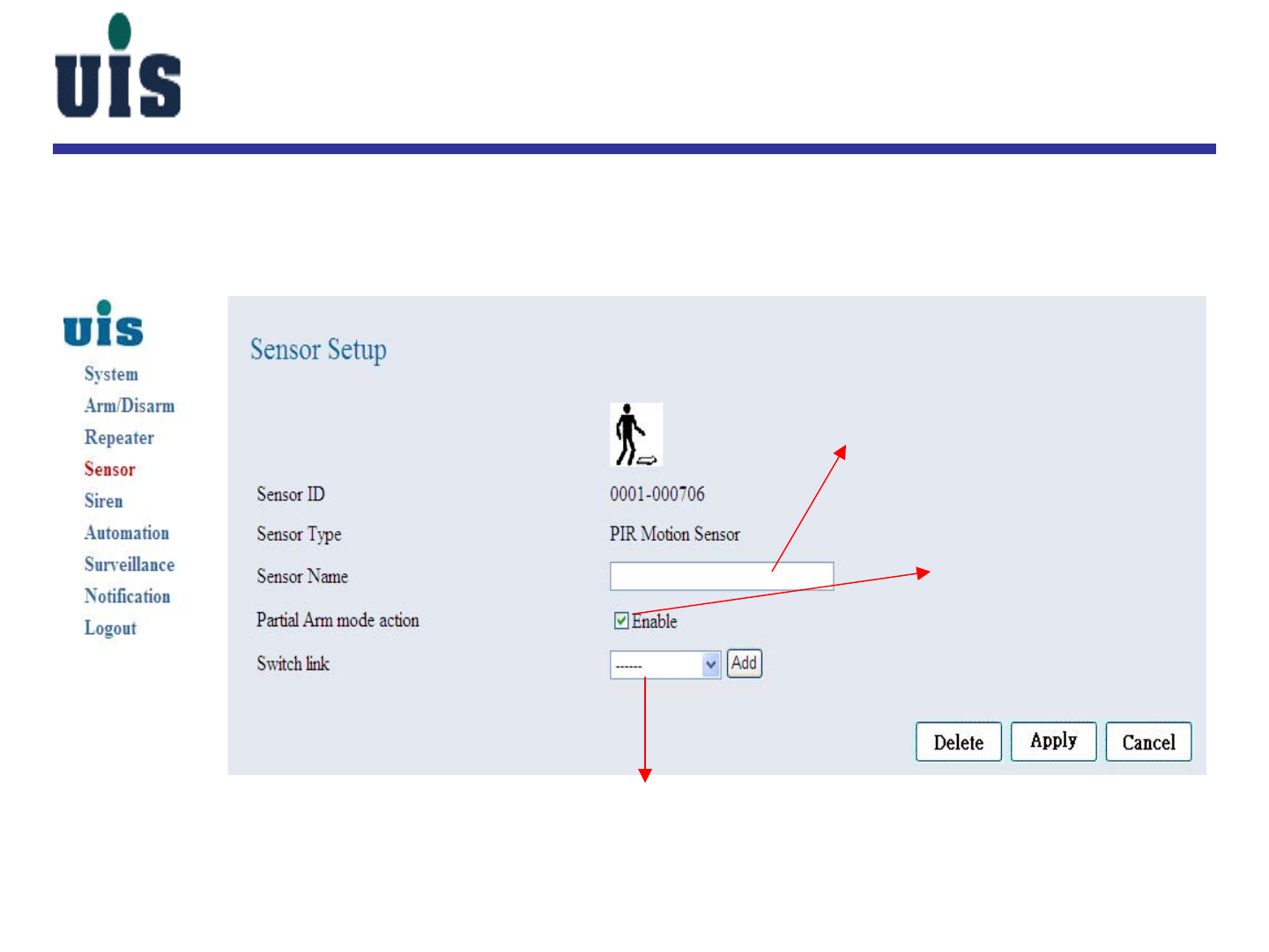
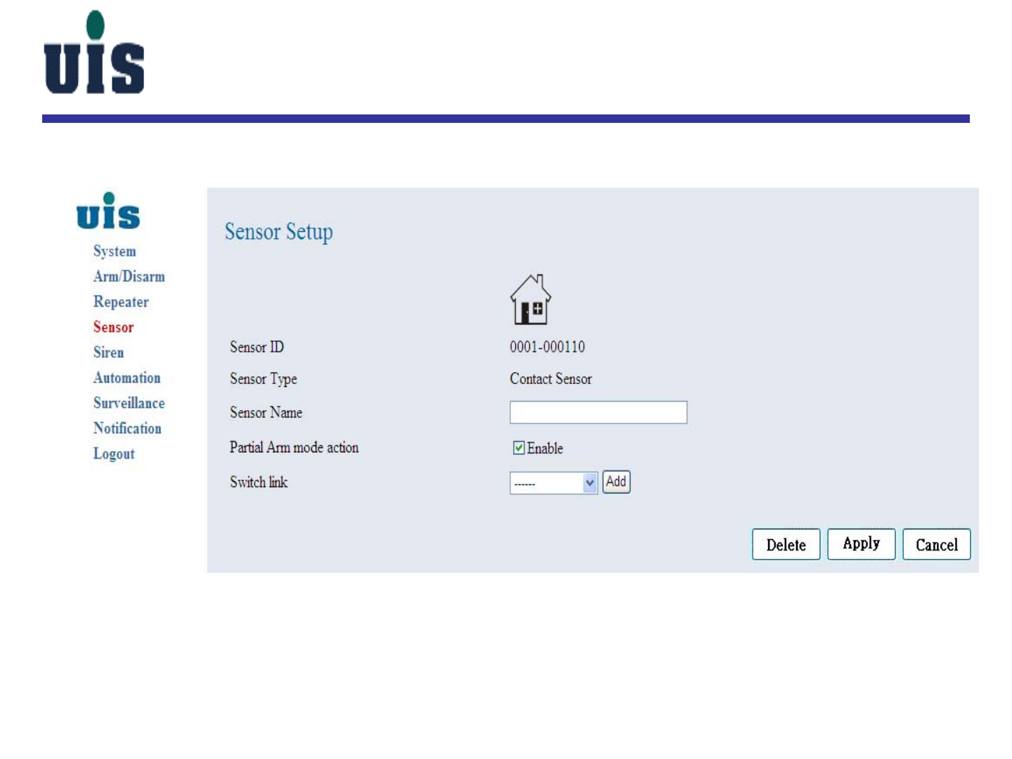
Sensor Setup
Step 25:Click “PIR Motion Sensor” to configure
user-definable alias
click here to enable the
Partial Arm mode
click here to bind the multiple links with the
automation-related controllers
Confidential 30
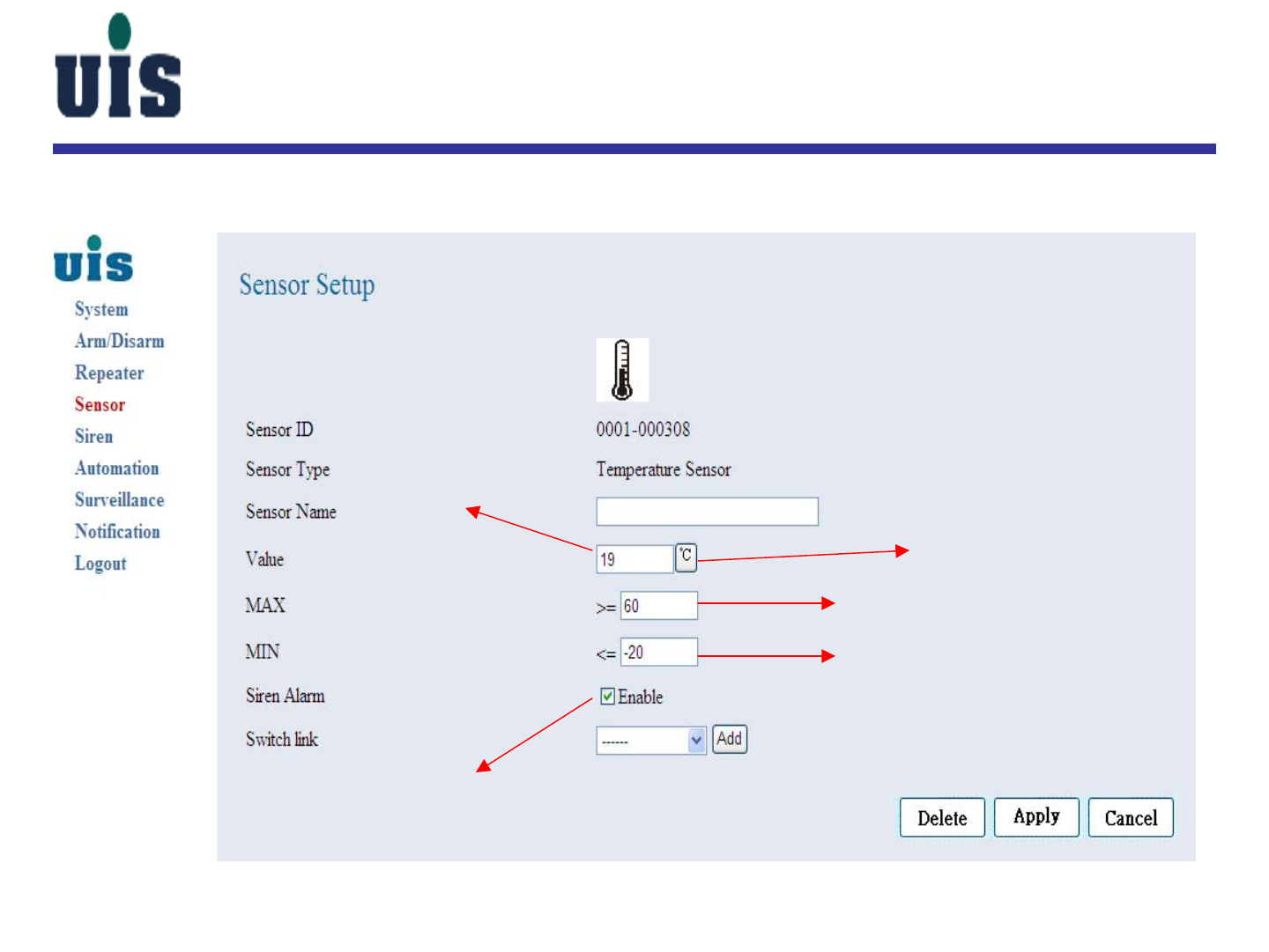
Sensor Setup
Step 26:Click “Temperature Sensor” to configure
current value
click here to swap the unit
key in the min. threshold value
click here to enable
Siren alarm once above
threshold be reached
key in the max. threshold value
Confidential 31
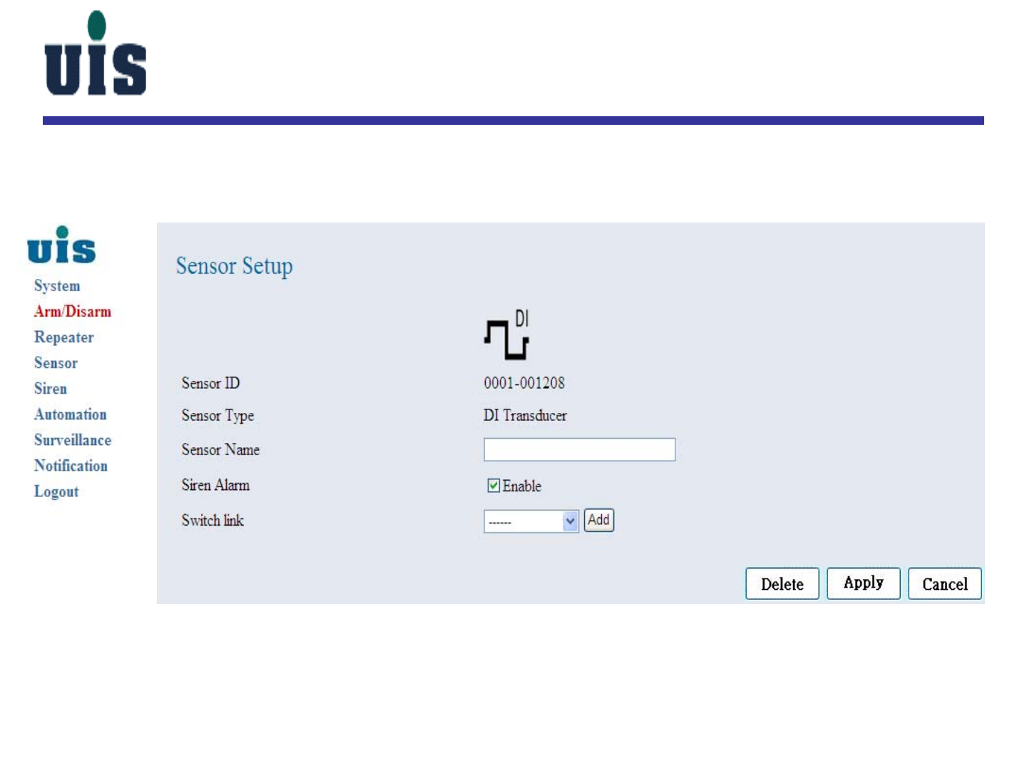
Sensor Setup
Step 27:Click “DI Transducer” to configure
Confidential 32
Sensor Setup
Step 28:Click “Contact Sensor” to configure
Confidential 33
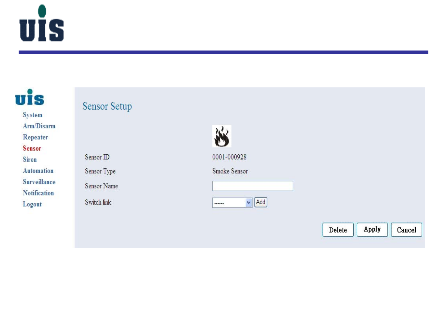
Sensor Setup
Step 29:Click “Smoke Sensor” to configure
Confidential 34
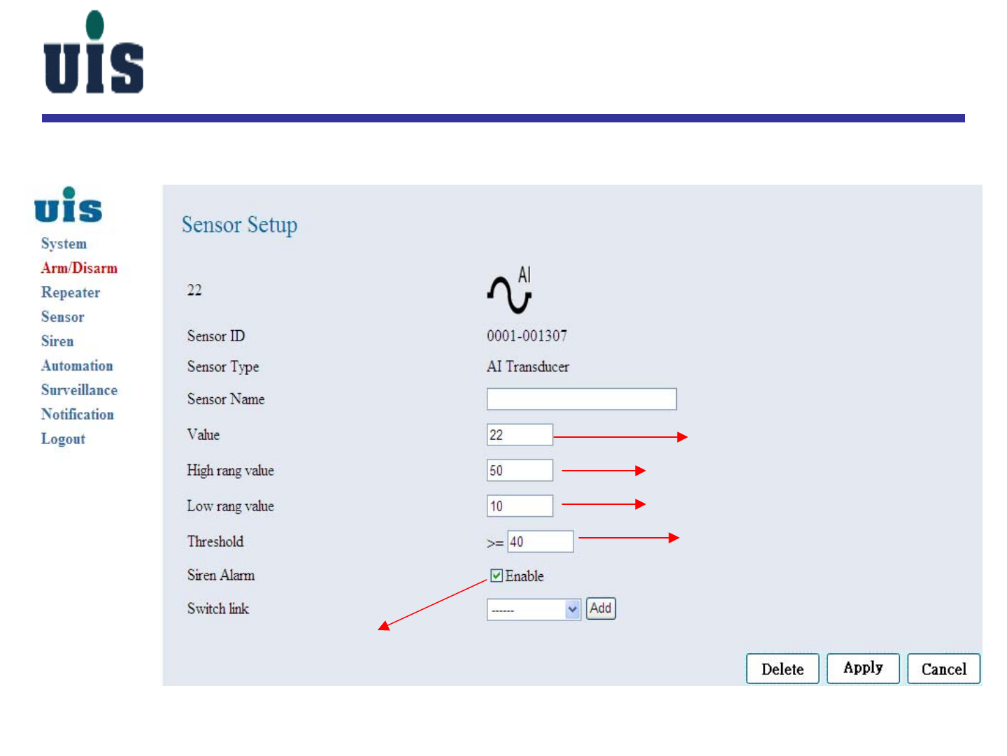
Sensor Setup
Step 30:Click “AI Transducer” to configure
current value
max value of attached sensor coverage
threshold value
click to enable Siren alarm
min value of attached sensor coverage

Confidential 35
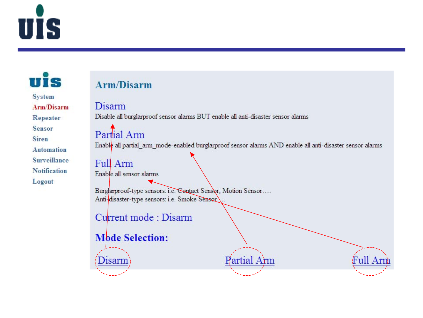
Arm/Disarm System
Confidential 36
Surveillance Setup
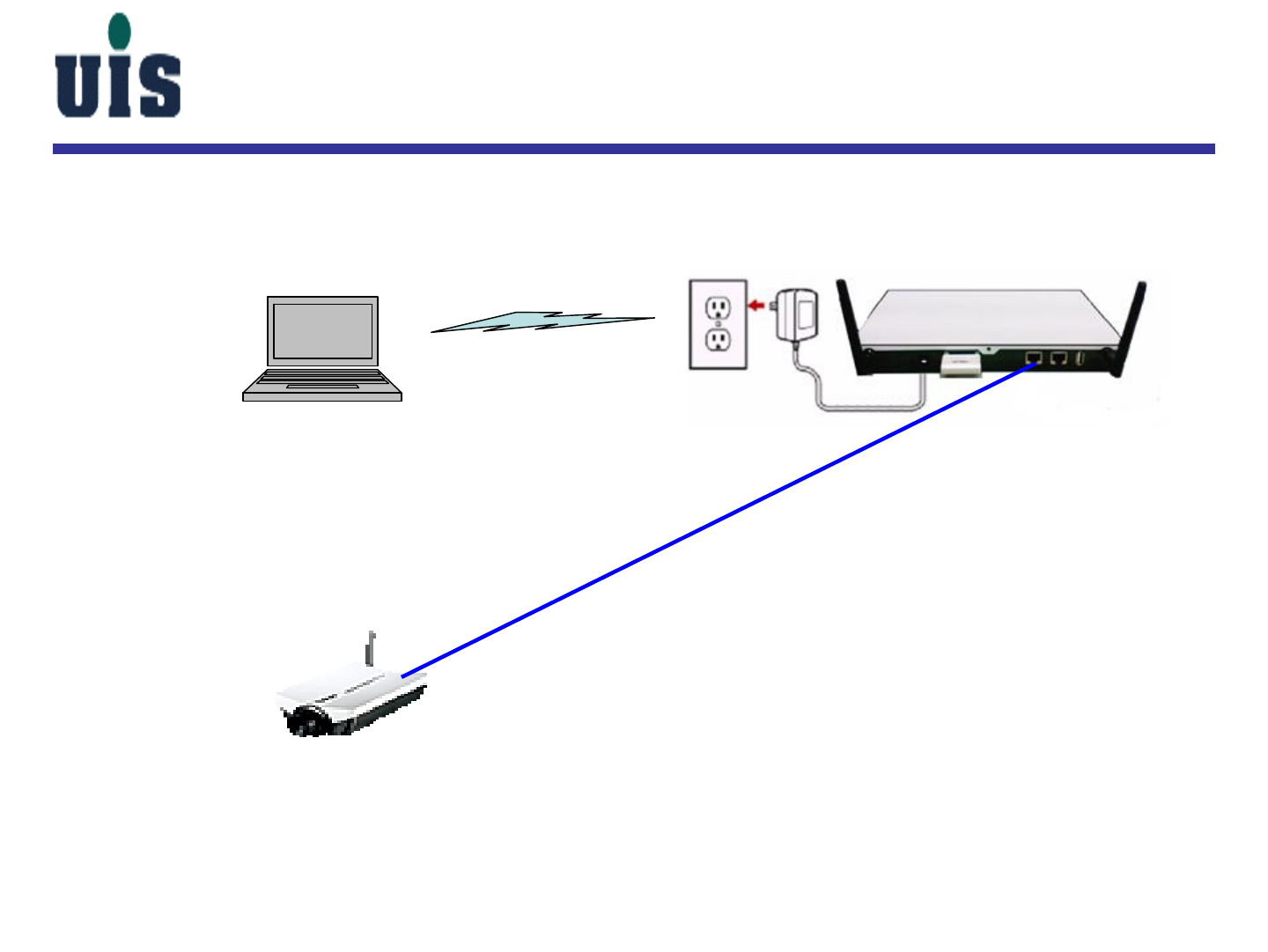
Step 31:Set up 3rd-party wired IP camera
LAN
UTP
WR-110/DHCP server
IP Camera
PC
1. Connect WR-110 and IP camera by UTP cable
OR thru external Ethernet switch
2. Gateway(WR-110) will release IP
address to IP camera by DHCP protocol
3. Open PC browser and type in IP camera’s
IP address to enter IP camera’s configuration
console
4. Configure IP camera’s IP address (fixed),
WiFi SSID, HTTP port# and RTSP port#
5. Reboot both Gateway and IP camera
WiFi
Confidential 37
Surveillance Setup
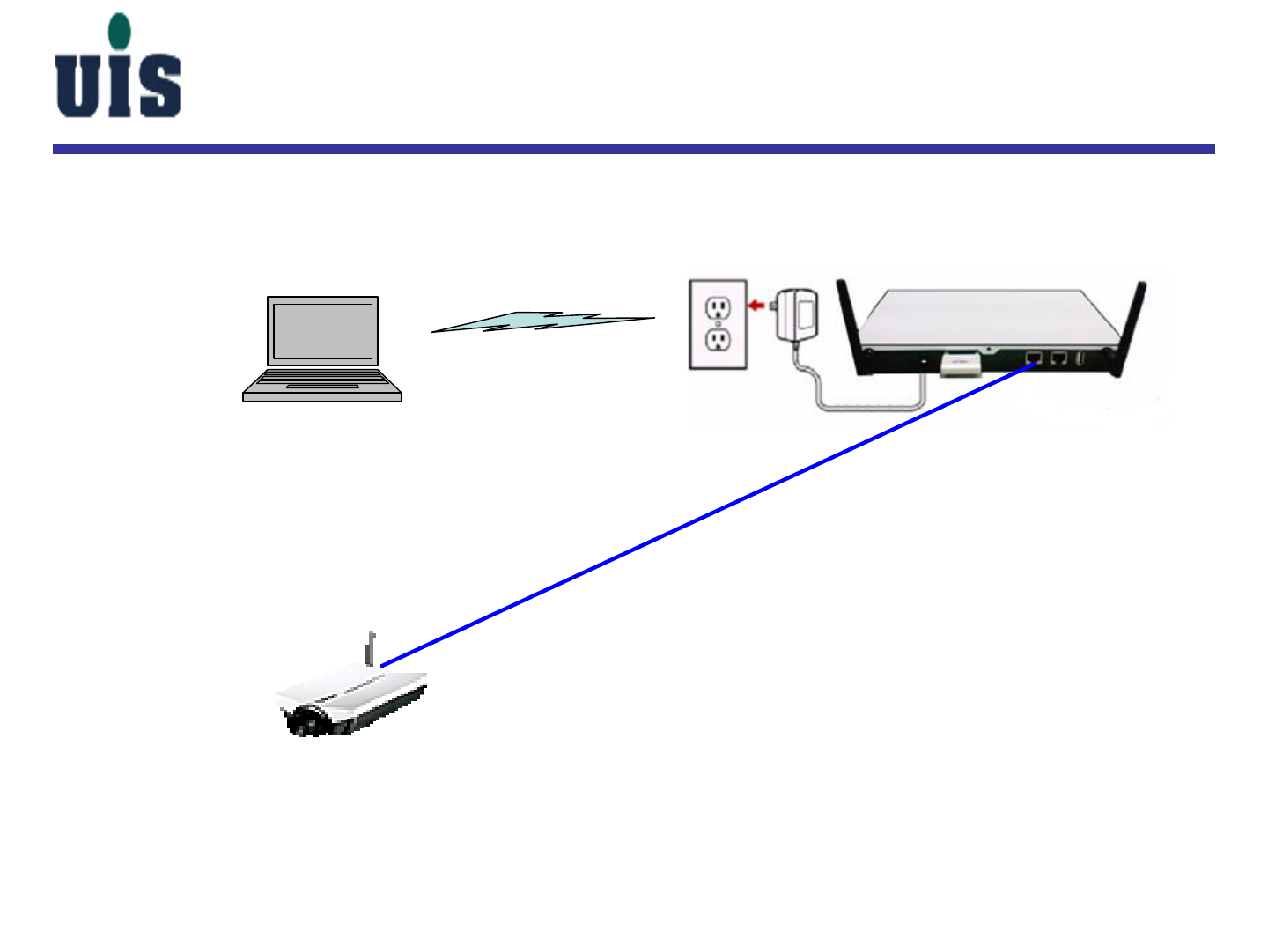
Step 31:Set up 3rd-party wireless IP camera
LAN
UTP
WR-110/DHCP server
IP Camera
PC
1. Connect WR-110 and IP camera by UTP cable
2. Gateway(WR-110) will release IP
address to IP camera by DHCP protocol
3. Open PC browser and type in IP camera’s
IP address to enter IP camera’s configuration
console
4. Configure IP camera’s IP address (fixed),
WiFi SSID, HTTP port# and RTSP port#
5. Disconnect the UTP connection and reboot
both Gateway and IP camera
WiFi
Confidential 38
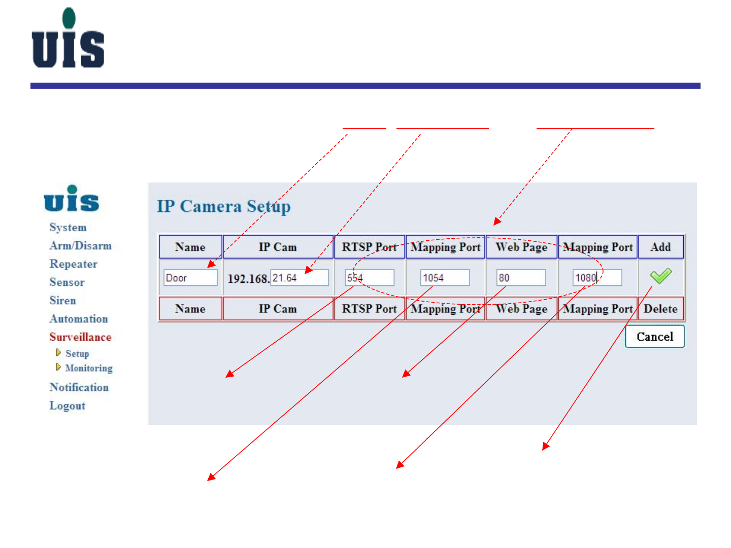
Surveillance Setup
Step 32:Key in IP Camera’s Alias, IP address, and Port mapping to
add into
click here to add IP camera
IP camera’s RTSP port#
Gateway’s RTSP port#
(must be above 1024)
IP camera’s HTTP port#
Gateway’s HTTP port#
(must be above 1024)
Confidential 39
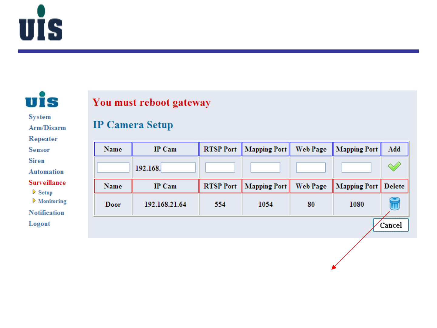
Surveillance Setup
Step 33:Reboot Gateway to take effect
click here to delete IP camera
Confidential 40
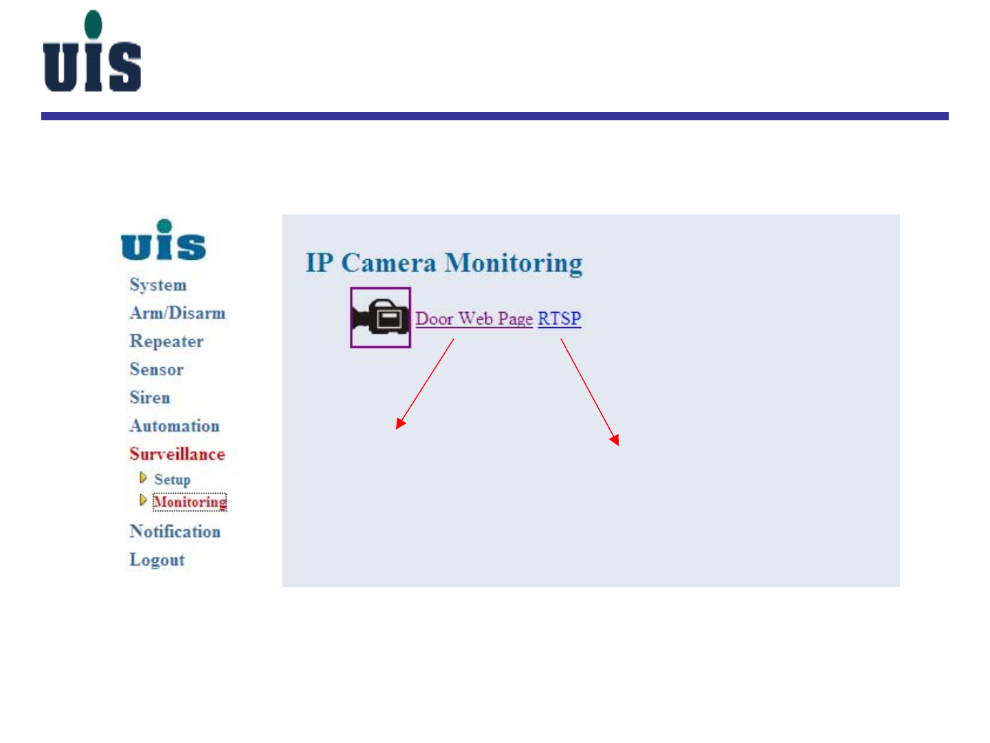
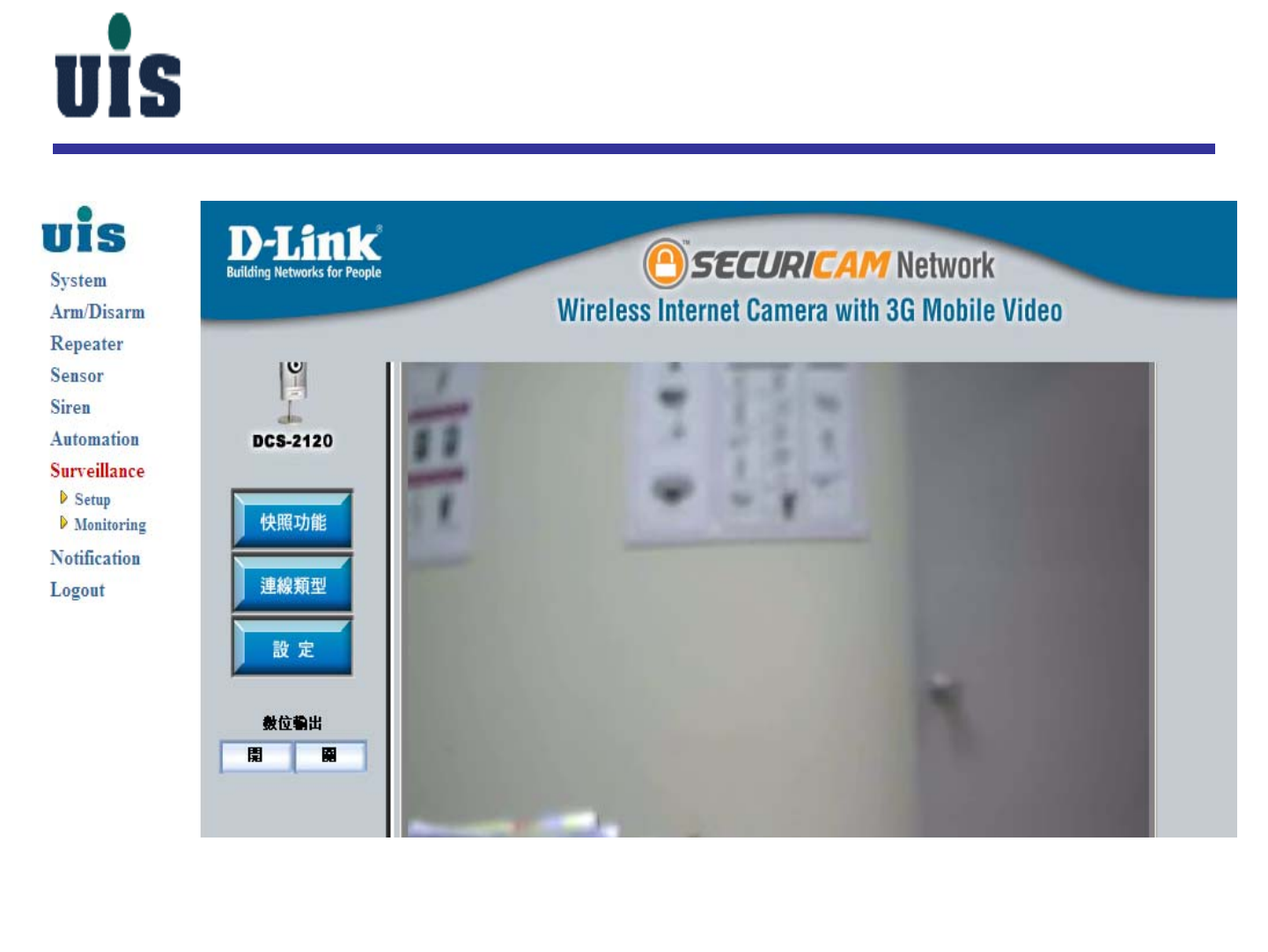
Surveillance Setup
Step 34:Choose IP camera to monitor
using HTTP to display using RTSP to display (to be available soon)
Confidential 41
Surveillance Setup
Confidential 42
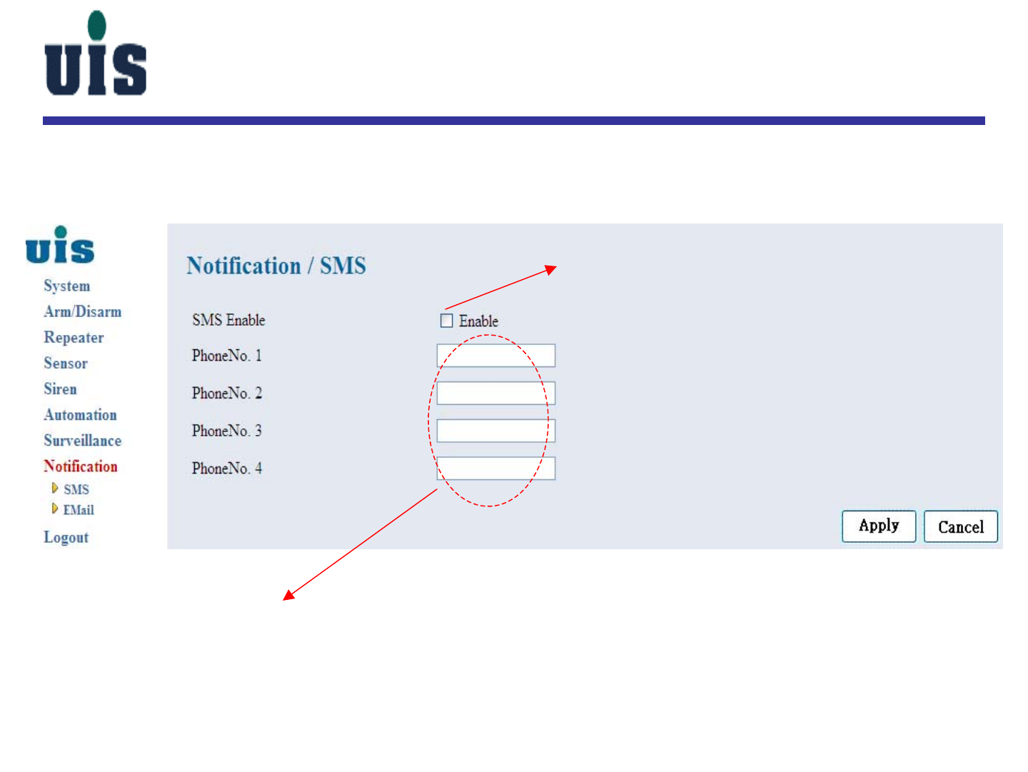
Notification Setup
Step 35:Click “Notification” to configure SMS notifications
click here to enable SMS notification
up to 4 mobile numbers could be entered
(country code + mobile num)
886987654321
886987654322
886987654323
886987654324
Confidential 43
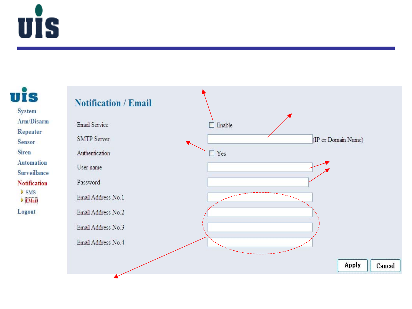
Notification Setup
Step 36:Click “Notification” to configure Email notifications
click here to enable email notification
key in SMTP server’s IP or Domain Name
click here to enable
SMTP authentication
as required
key in username/password
up to 4 email addresses could be entered
sales@wss.uisco.com.tw
Confidential 44
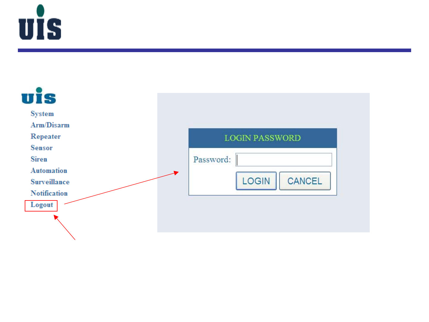
System Logout
Step 37:Click “Logout” to logout the system
click

Confidential 45
WR-110
Touch Console Configuration Guide
Confidential 46
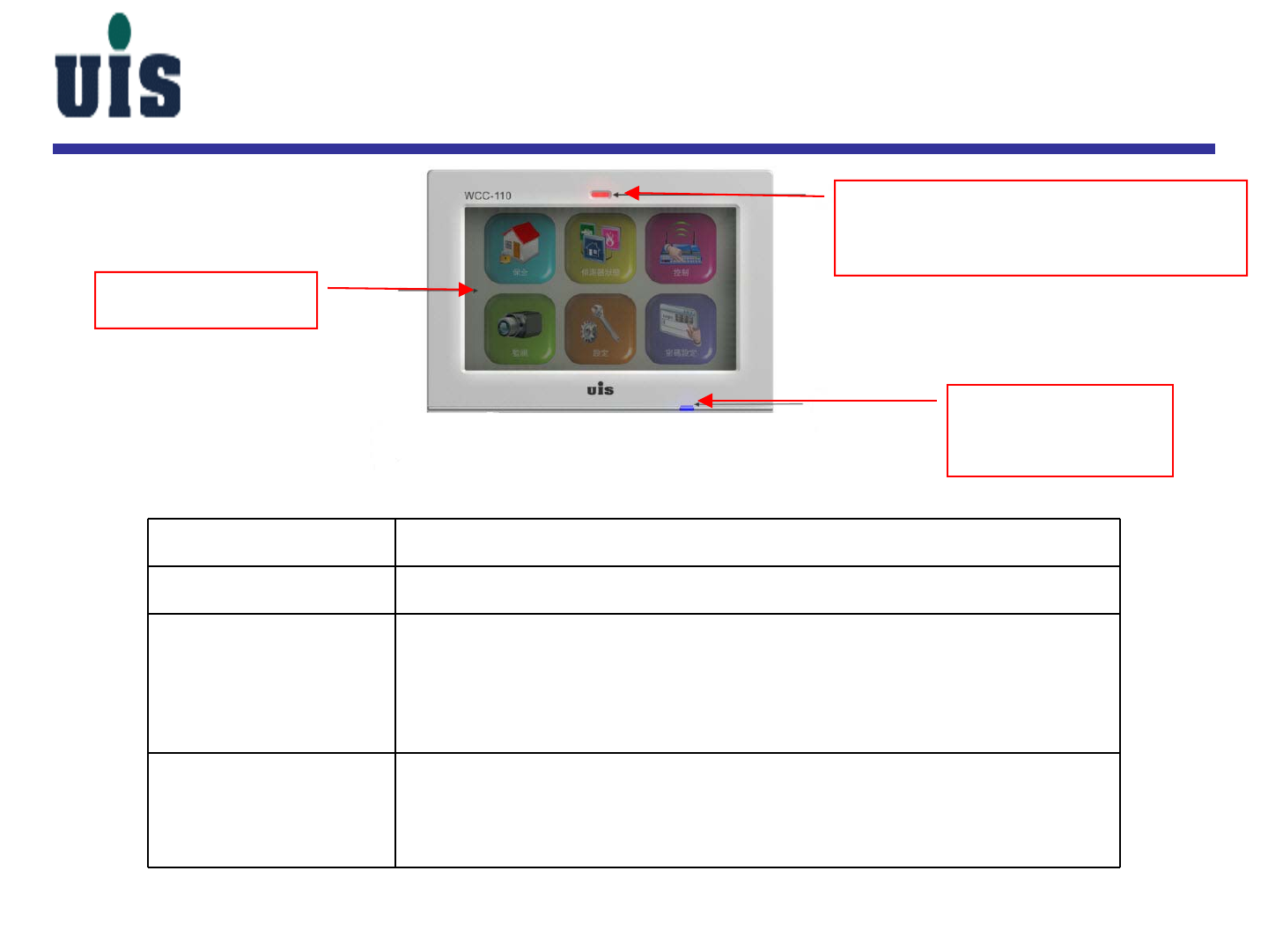
Item Description
Touch screen 7” 800x480 16:9 WVGA TFT color LCD displays with Touch panel
Battery status
indicators Dual Color LED(Green, Red) to show the battery status of
1. In charging ( AC power on) - Red LED blinking ,
2.Battery discharge- Yellow continue ,
3.low battery – Red LED continue on
4. Normal(AC power on, battery high) – Green LED continue on
Arm/Disarm status
indicators/
Boot status
Dual Color(Blue,Red)LED to show the status of the Arm/Disarm Status
1.Full(Partial) Arm: Red LED blinking ;
2.Disarm: Blue continue on
3.Booting --Blue LED blinking
Touch screen
Battery status
indicators
Arm/Disarm status indicators/
Boot status
WCC-110 / Front View
Confidential 47
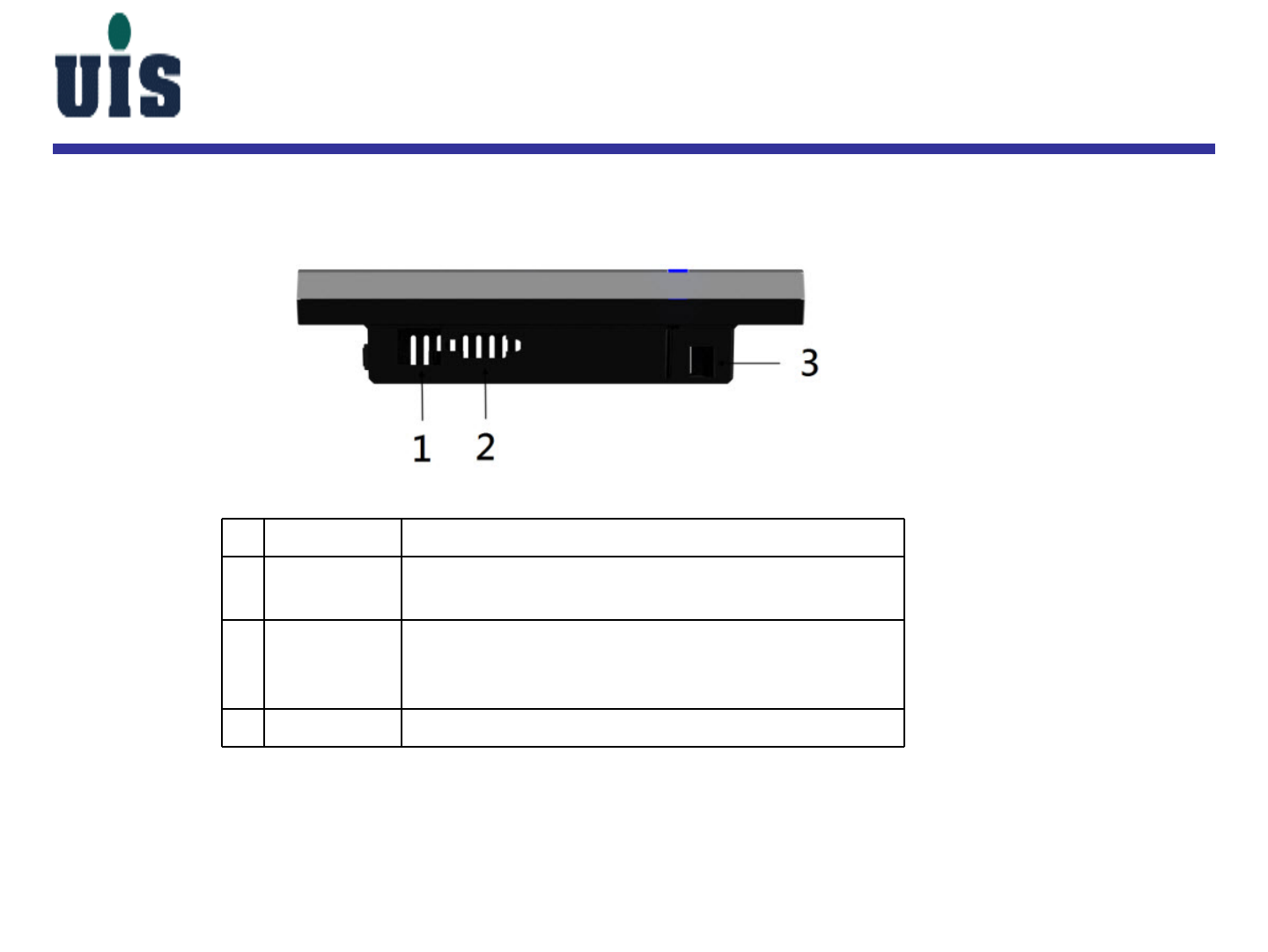
# Item Description
1 Ethernet
(RJ-45)
port
Connects to an Ethernet 10/100 based network.
2 External
display
(VGA) port
Connects to a display device (e.g. external monitor,
LCD projector.
3 DC-in jack Connects to an AC adapter.
WCC-110 / Back View
Confidential 48
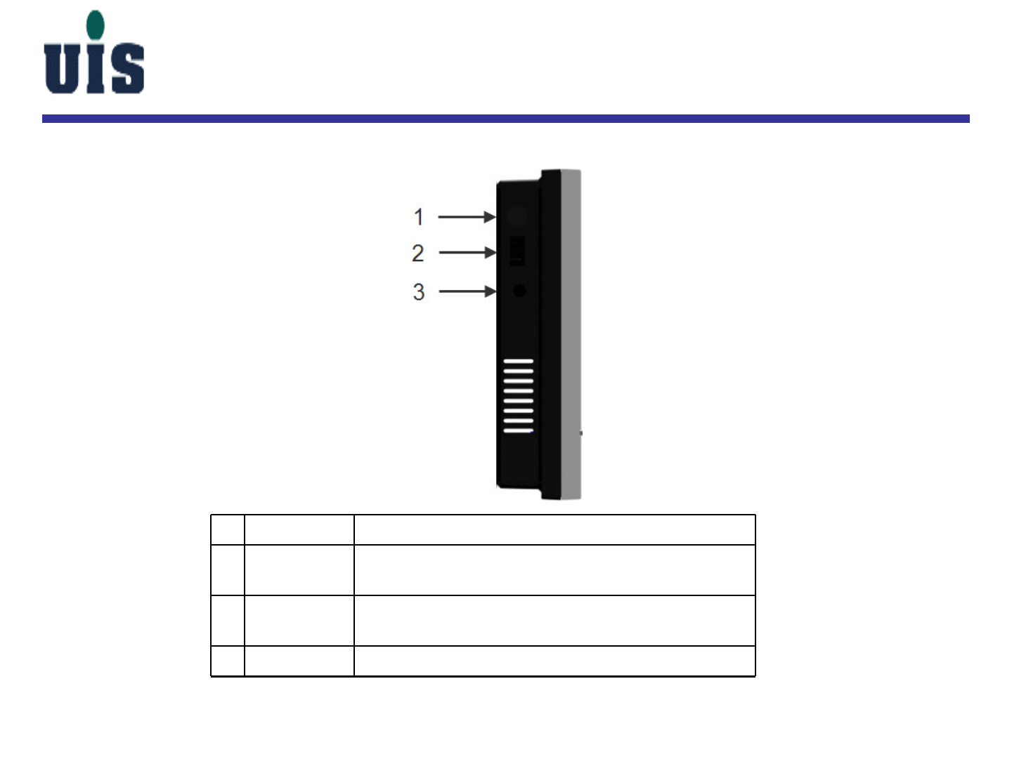
# Item Description
1 Power
button Turn on/off Console Controller
2 USB
2.0/1.1 port Connects to USB devices (e.g. USB camera, USB
keyboard).
3 Speaker
jack Connects to audio devices (e.g. external speakers).
WCC-110 / Side View

Confidential 49
WCC-110 Setup
Power ON :
1. Plug in the power adapter
2. Push the power button to power on the device
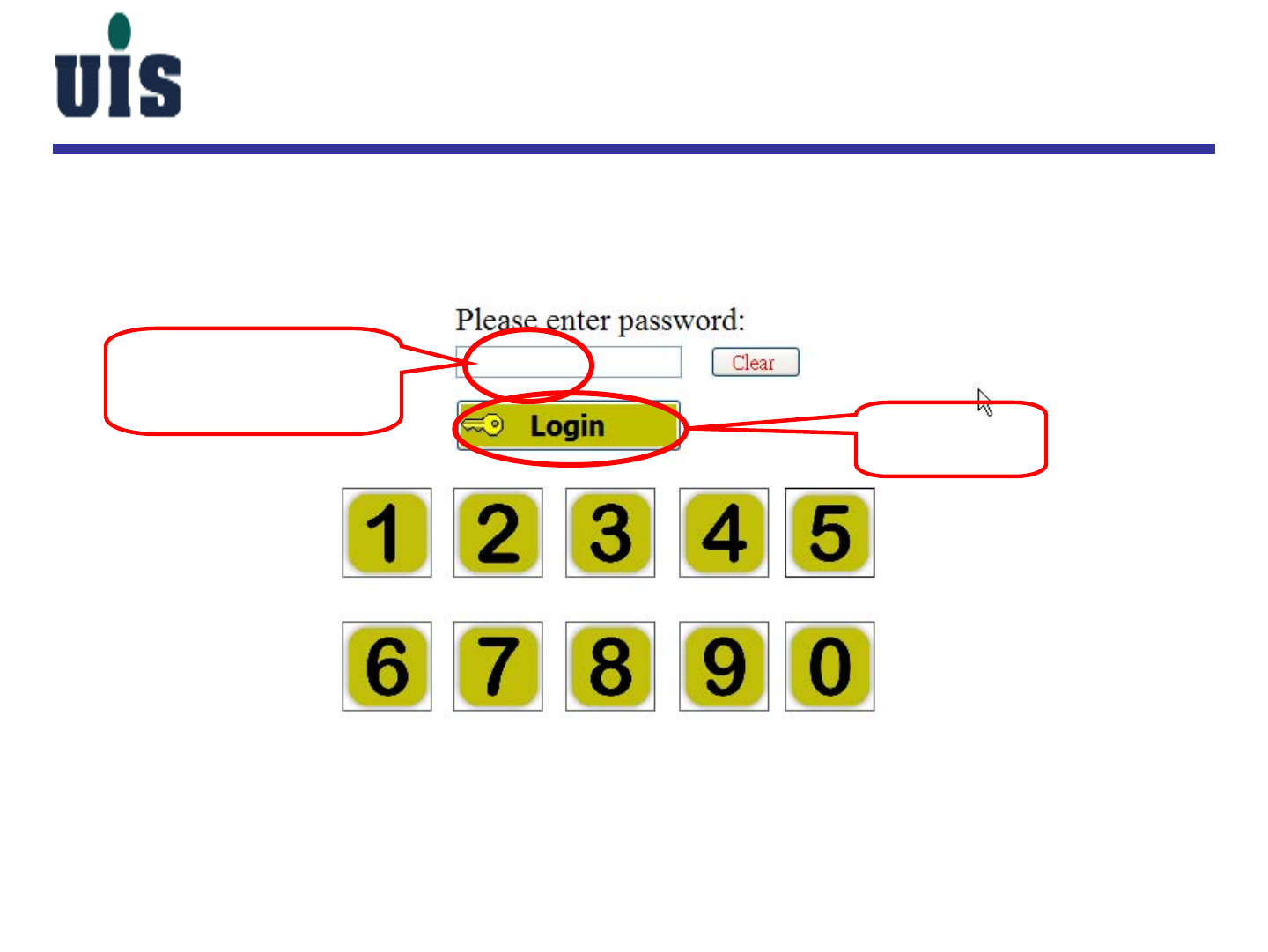
Confidential 50
1. Key in password
The default value is
“123” 2. Click here
to login
WCC-110 Setup
Confidential 51
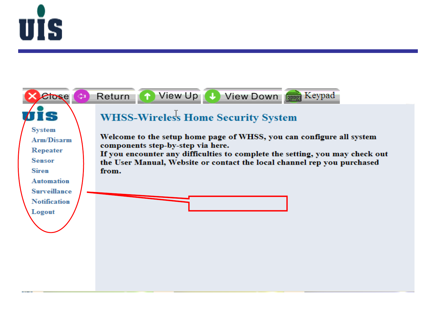
Touch here to enter
into the setup main
console
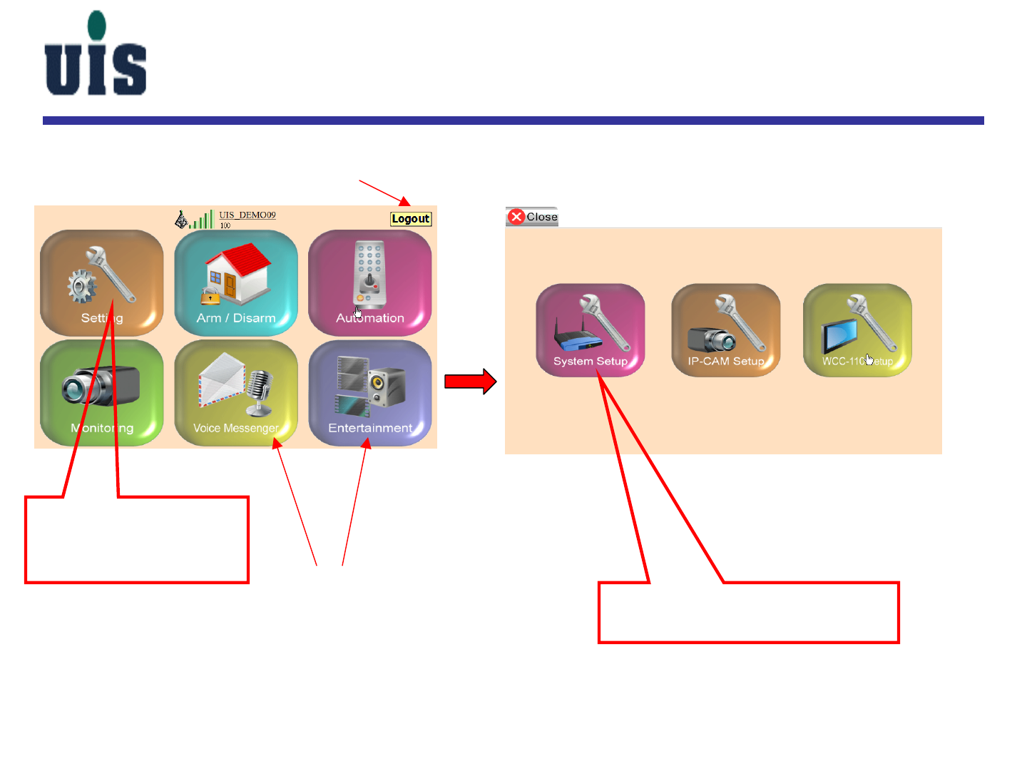
WCC-110 Setup
Touch here to enter into the
Gateway setup screen
Click here to logout
To be available
Confidential 52
Same as PC console
WCC-110 Setup
Confidential 53
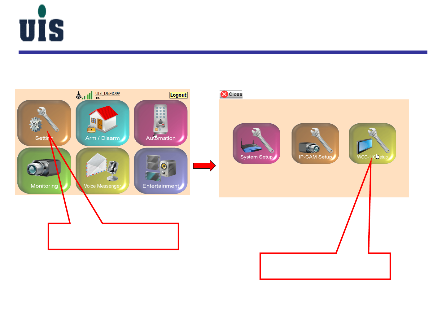
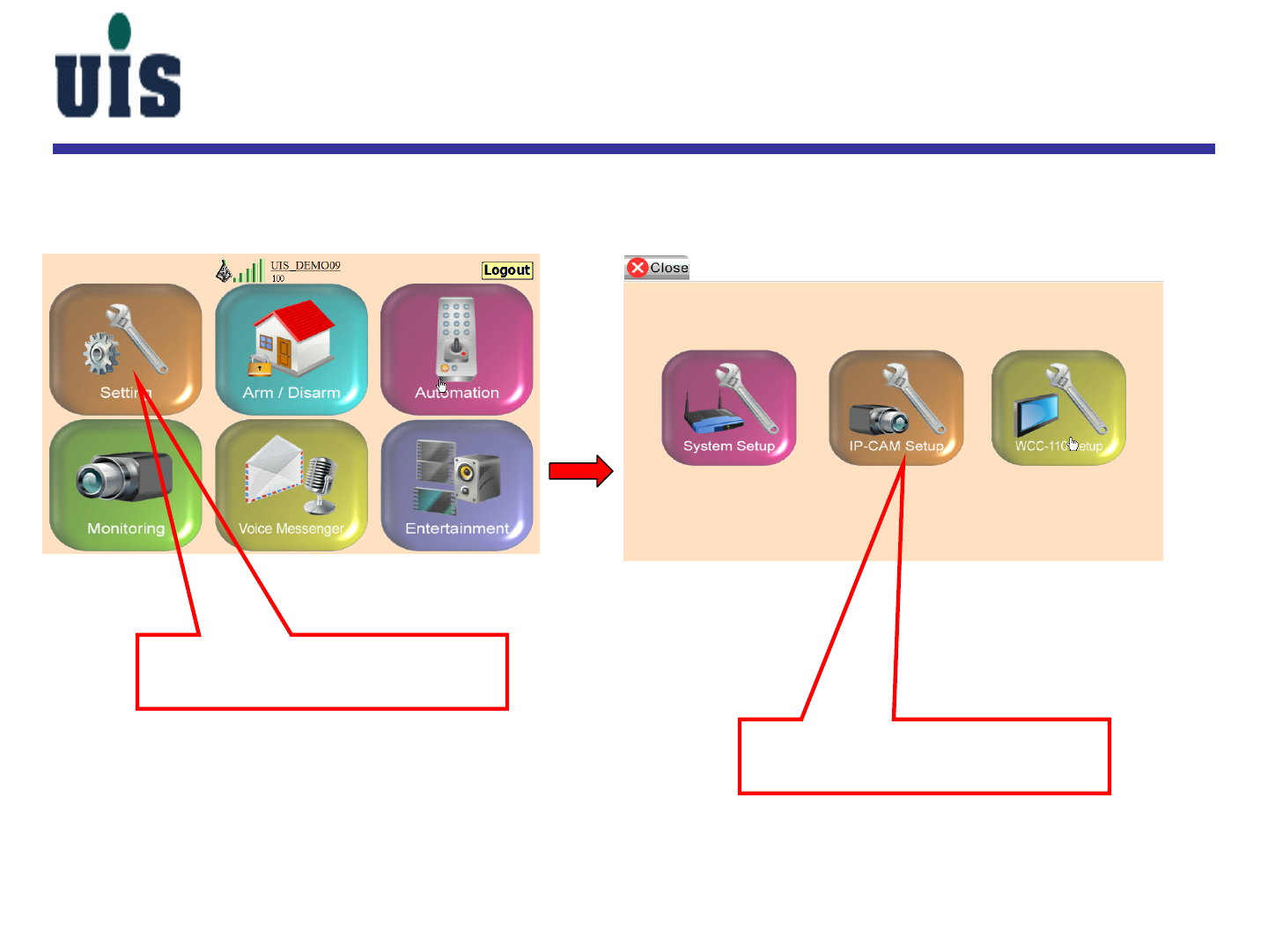
Touch here to enter into the
setup main console
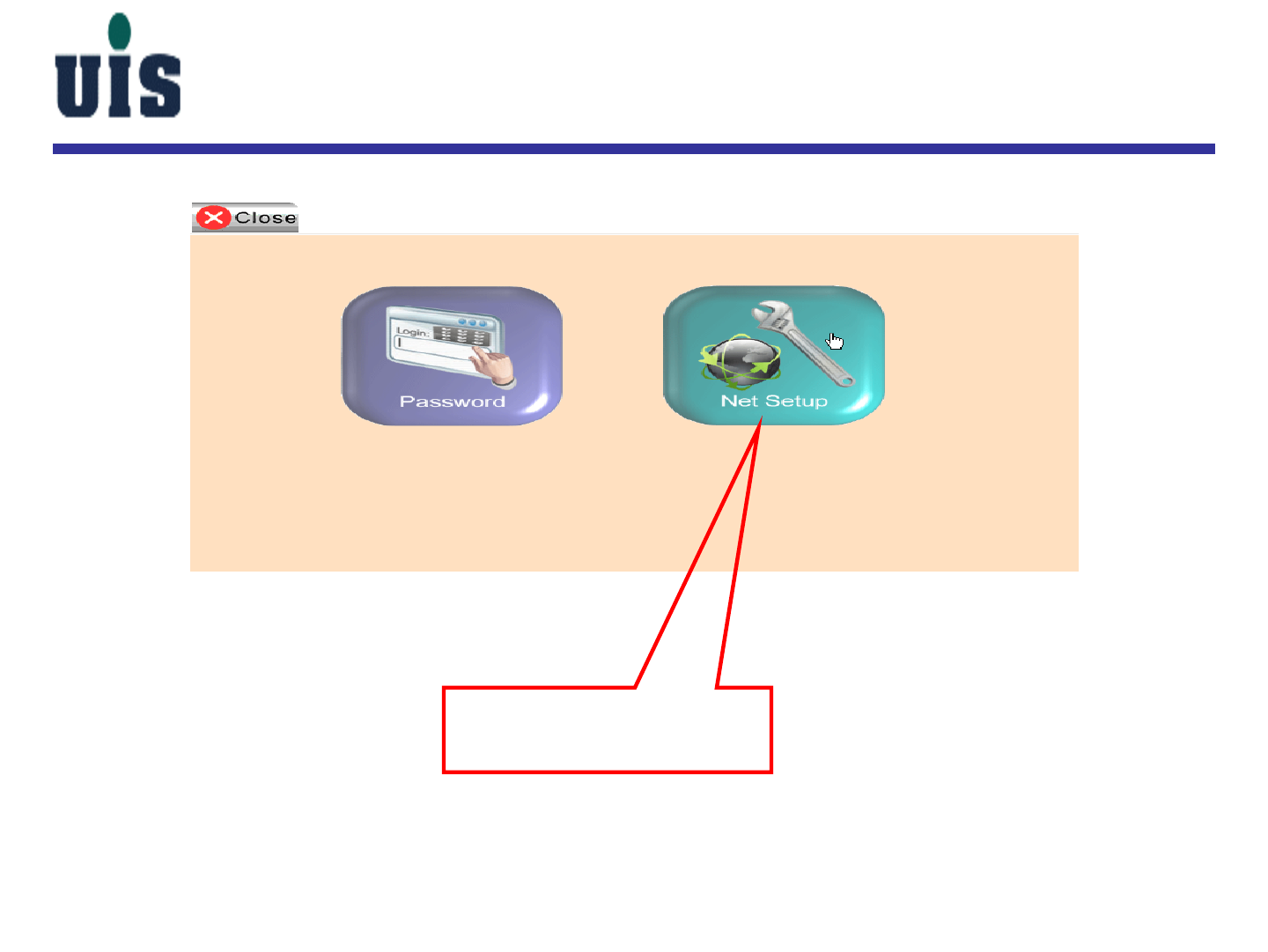
WCC-110 Setup
Touch here to enter into the
WCC-110 setup screen
Confidential 54
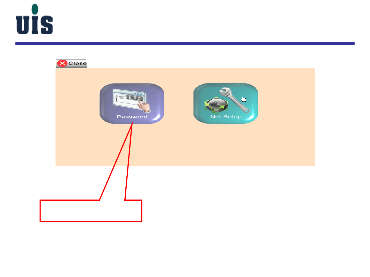
WCC-110 Setup
Touch here to enter into
the password setup screen
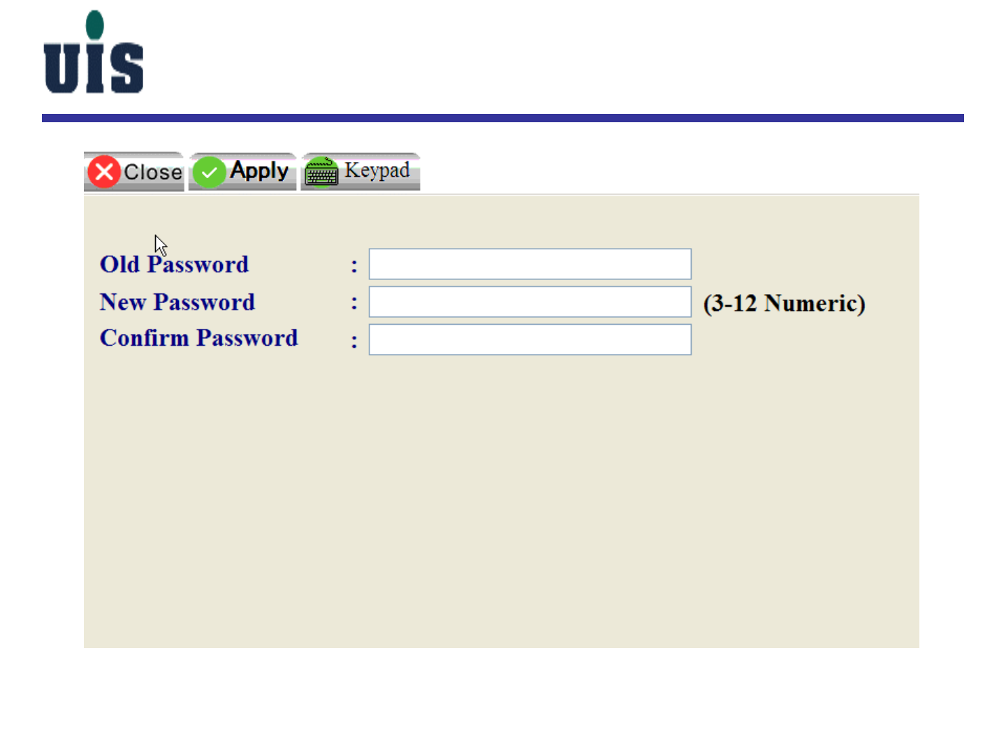
Confidential 55
WCC-110 Setup
Confidential 56
WCC-110 Setup
Touch here to enter into
the network setup screen
Confidential 57
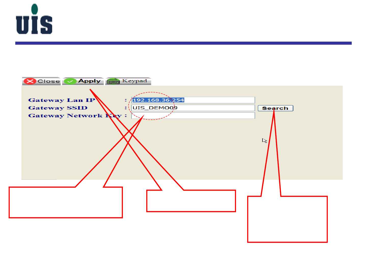
3. Click here to activate
all settings
1. Key in Gateway’s LAN IP,
SSID(if know) & WiFi network
key(if have) 2. Click here to
searching for WiFi
SSID(if don’t know),
move to the next
page to continue
WCC-110 Setup
Confidential 58
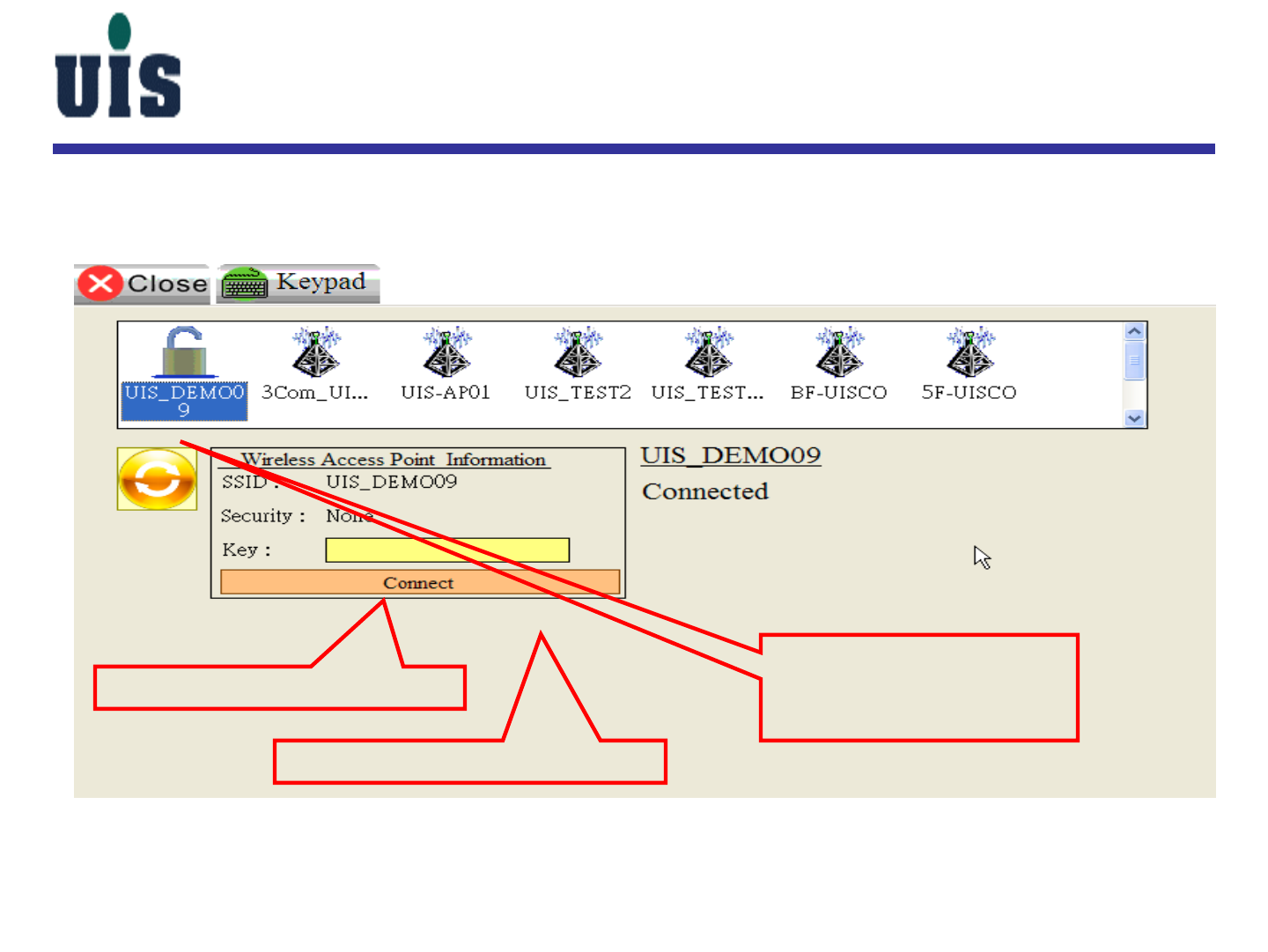
1. Choose the right SSID
that you’re going to get
connected with Gateway
WCC-110 Setup
2. Key-in the WiFi key if have
3. Click here to get connected
Confidential 59
Touch here to enter into the
setup main console
WCC-110 Setup
Touch here to enter into the
IP Camera setup screen
Confidential 60
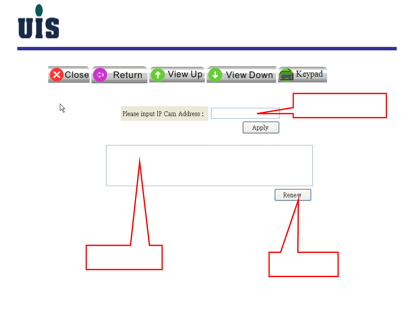
WCC-110 Setup
Key-in IP Camera’s IP
address(if know)
DHCP IP address
release table Click here to
renew the table

Confidential 61
Content
1. System Installation Guide
2. User Operation Guide
3. Troubleshooting Guide
4. Application Guide
Confidential 62
PC/HTTP Console
Confidential 63
PC/HTTP Console
Show up the real-time
mode once changed
Confidential 64
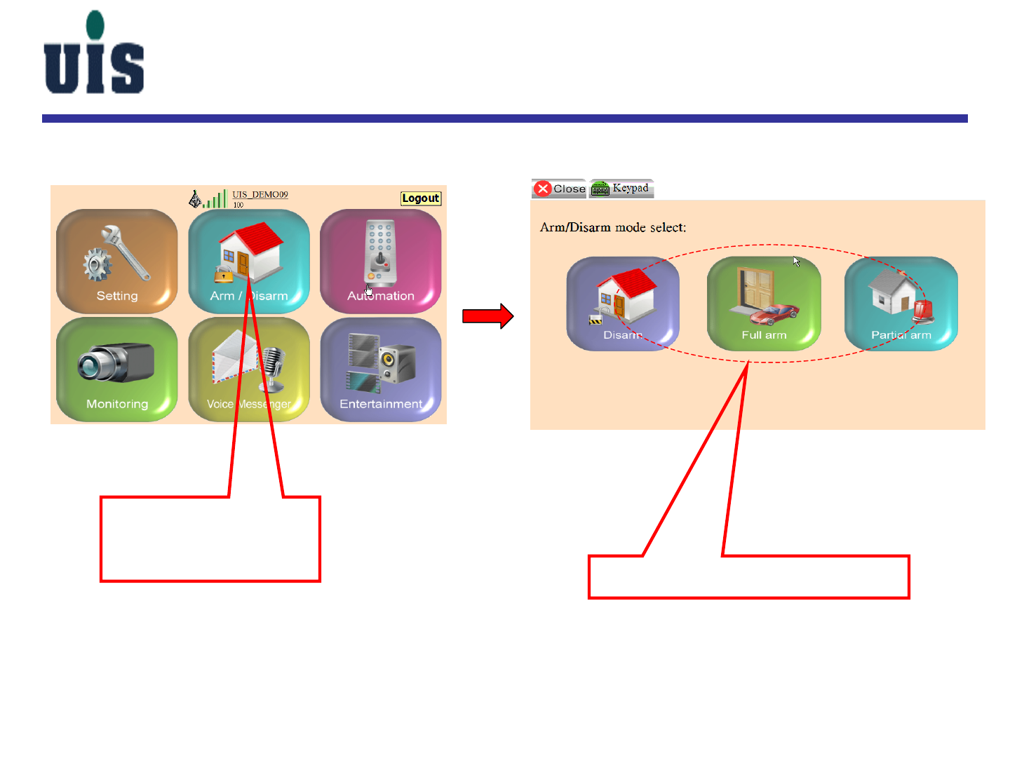
Touch here to enter
into the Arm/Disarm
main console
WCC-110 Console
Choose either mode you prefer
Confidential 65
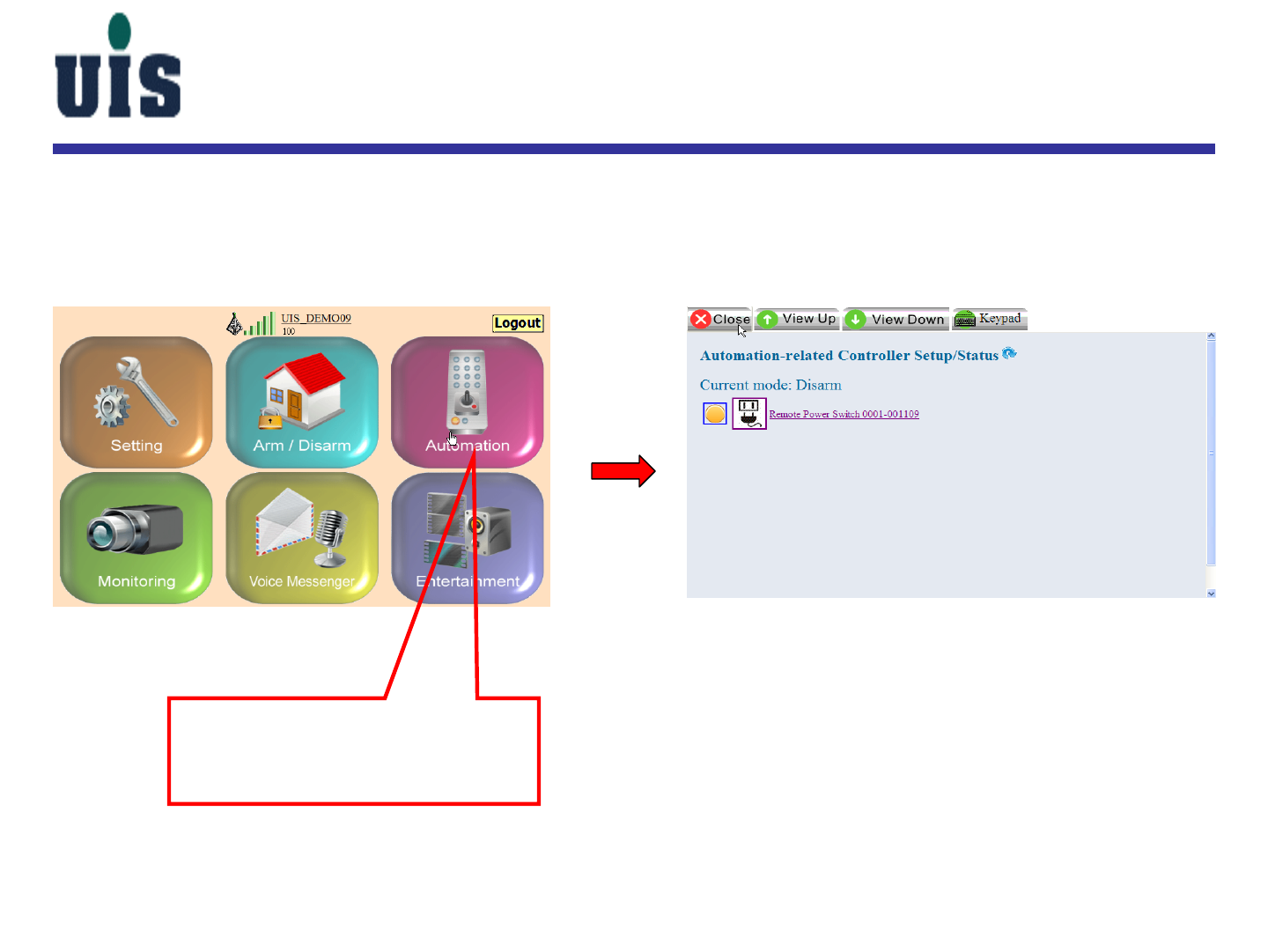
Touch here to enter into the
automation-related main
console
WCC-110 Console
Confidential 66
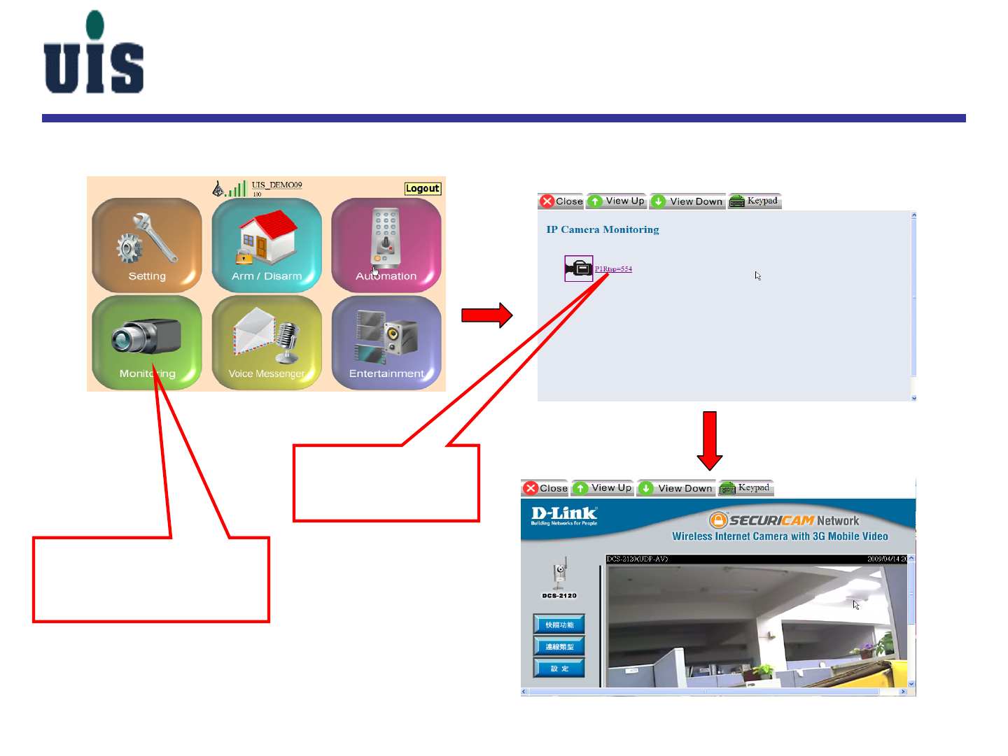
1. Touch here to enter
into the Monitoring
main console
2. Choose the IP
Cam you want to
watch
WCC-110 Console

Confidential 67
Content
1. System Installation Guide
2. User Operation Guide
3. Troubleshooting Guide
4. Application Guide
Confidential 68
Troubleshooting Tips
Partial Arm mode be disabled
Confidential 69
Troubleshooting Tips
sensor(vs. magnet) in open mode
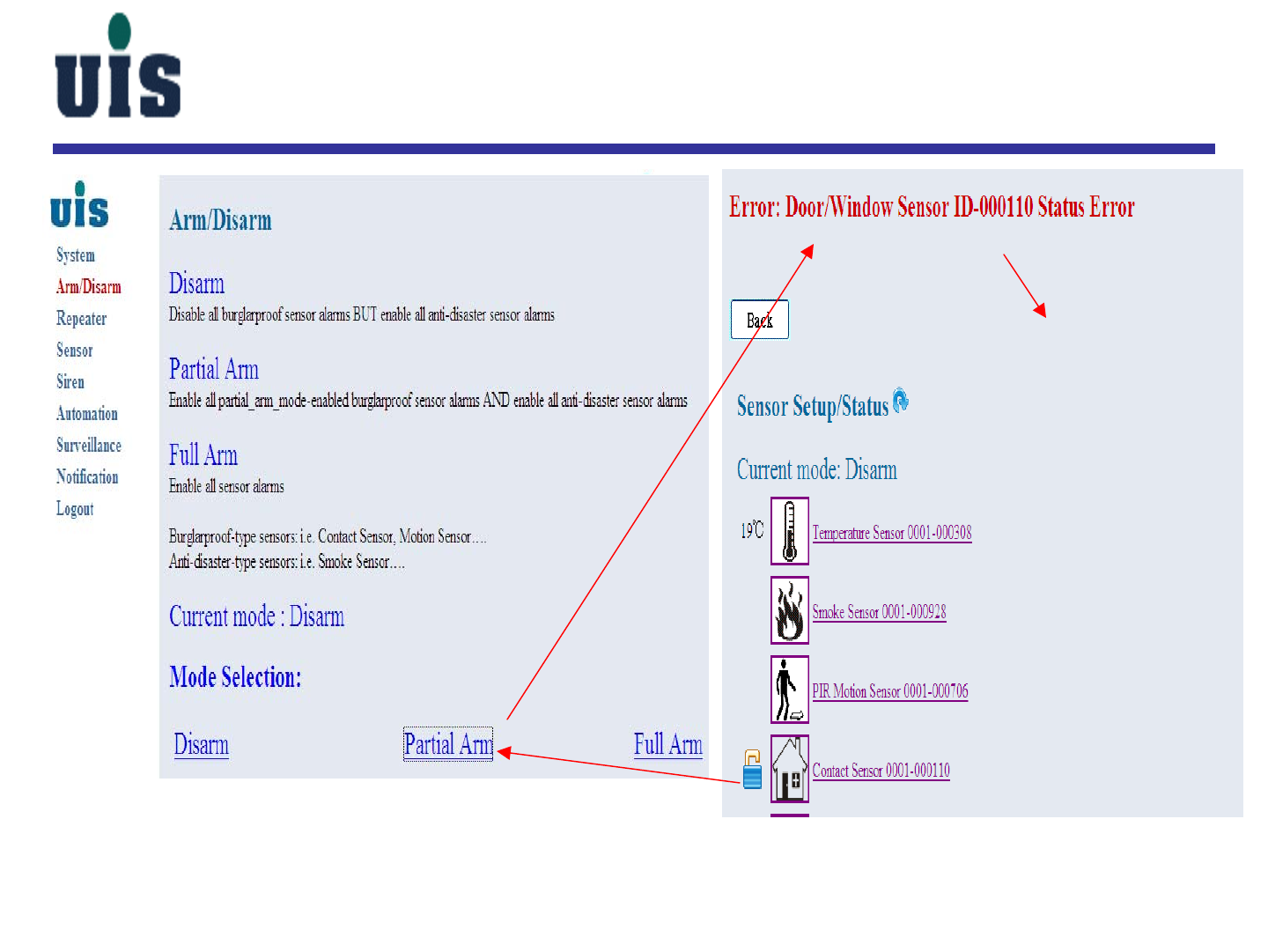
Confidential 70
Troubleshooting Tips
you can’t enable Partial
or Full Arm mode while
WCS is in open mode
Confidential 71
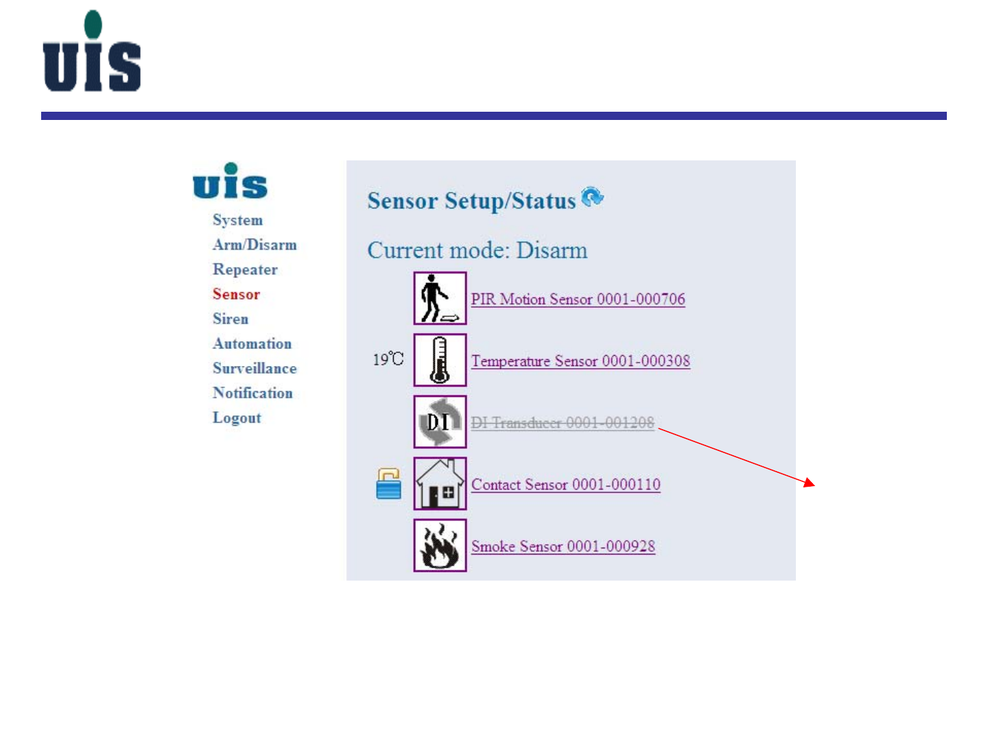
Troubleshooting Tips
disconnected, has to
re-do the binding with
Repeater (or, you may
have to delete it first)

Confidential 72
Content
1. System Installation Guide
2. User Operation Guide
3. Troubleshooting Guide
4. Application Guide
Confidential 73
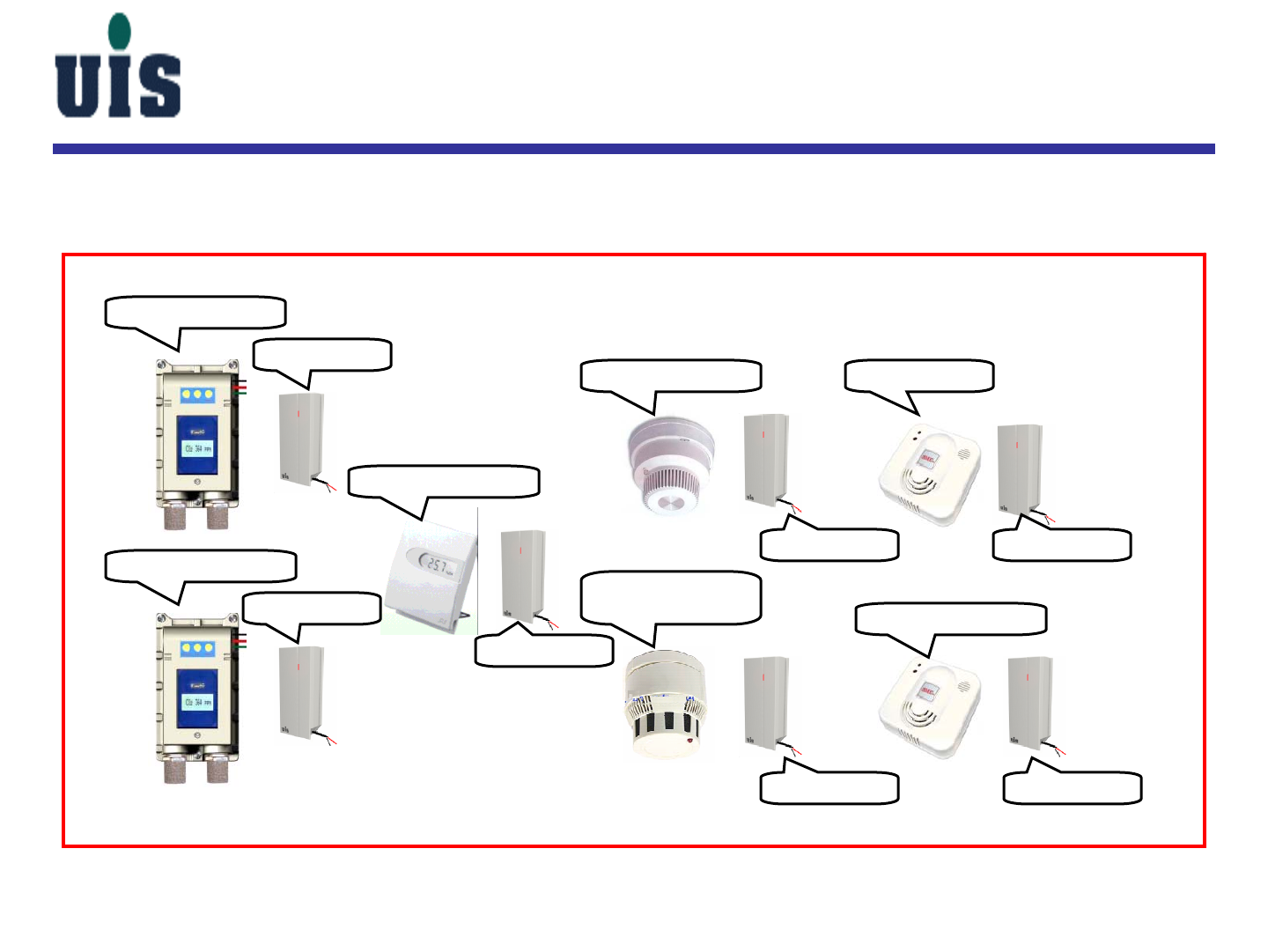
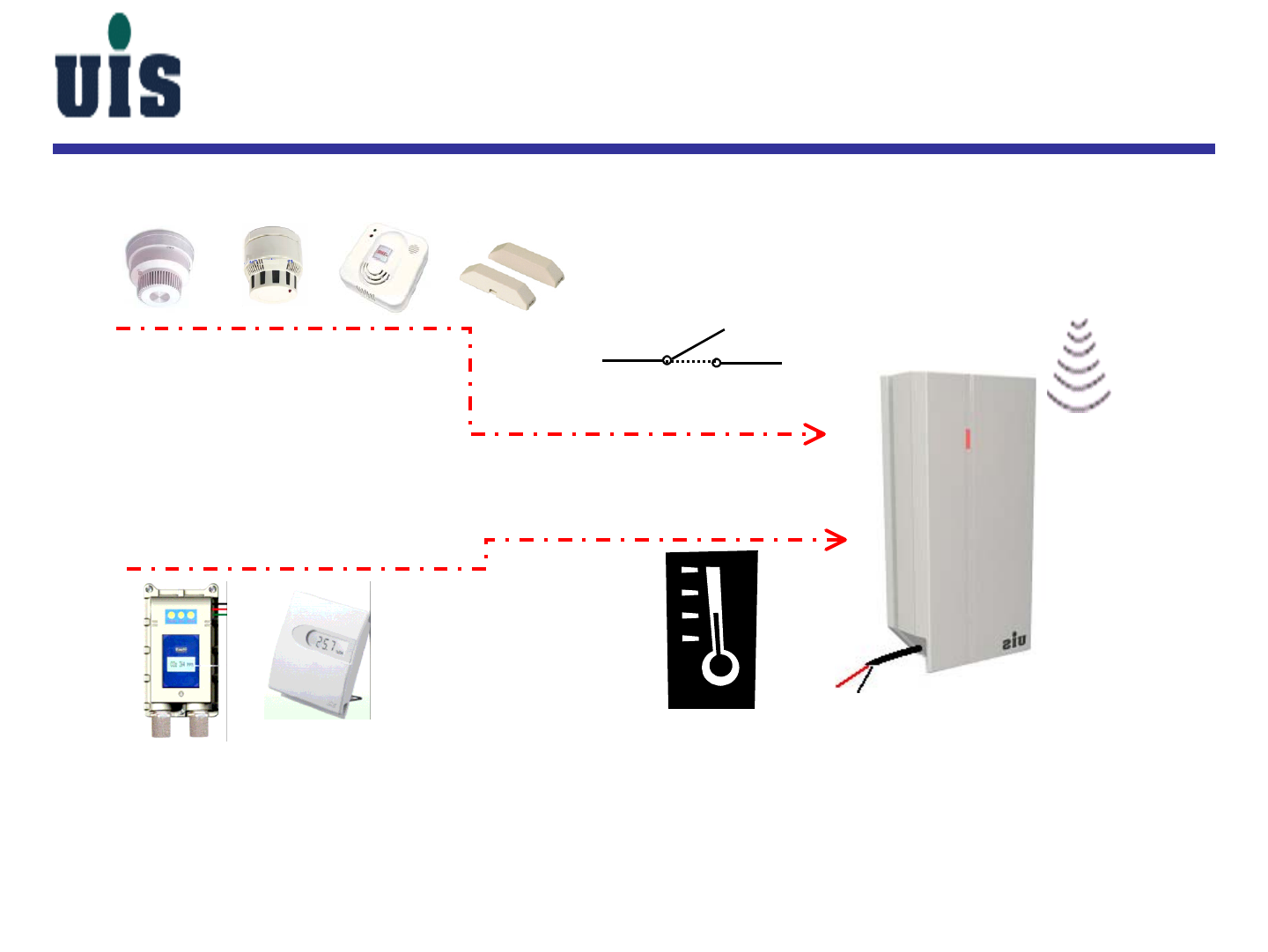
4-20mA CO Detector
4-20mA GAS Detector
AI Transducer
AI Transducer
Temperature Sensor
AI Transducer
NC/NO CO Detector
NC/NO SMOKE
Detector
DI Transducer
DI Transducer
DI Transducer
DI Transducer
NC Fire Alarm
NC/NO GAS Detector
AI/DI Transducer Applications
Confidential 74
AI/DI Transducer Applications
NC/NO_relay-type
disaster sensor
Linear-type (data retrievable)
disaster sensor
DI Input
4-20mA AI Input
AI/DI Transducer
-
+

Confidential 75
AI/DI Transducer Applications
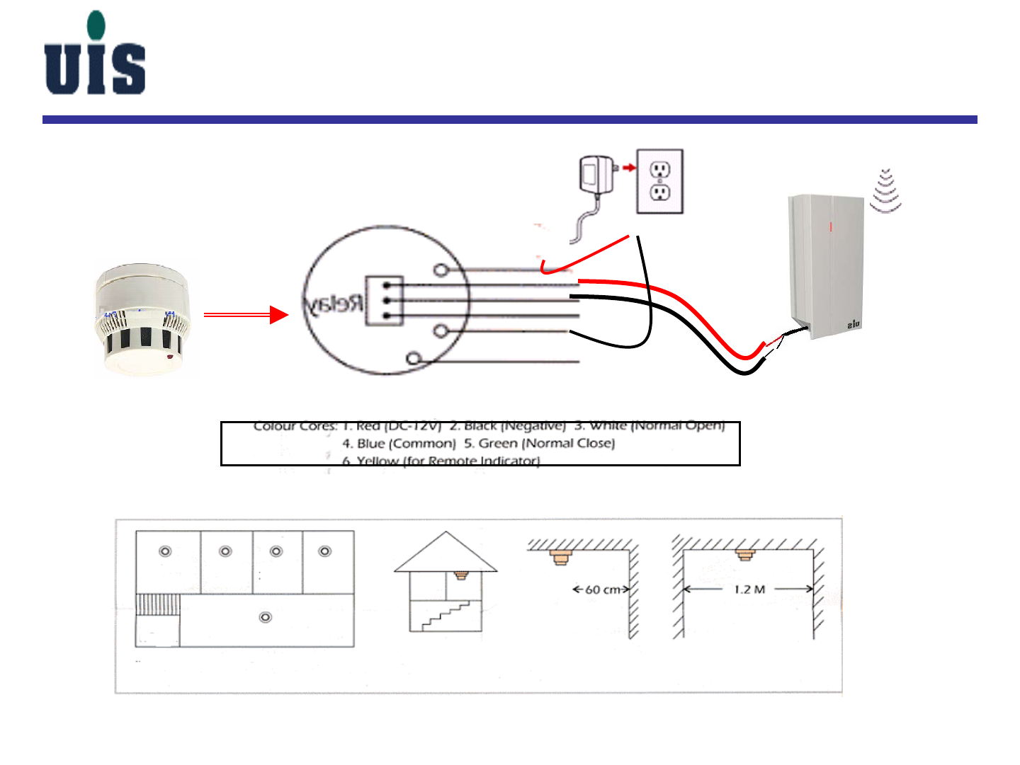
DI Transducer
DC+
DC-
DC12v
Adapter
,+
-
CO sensor
Confidential 76
AI/DI Transducer Applications
Installing location
kitchen Bed
room Bed
room Bed
room
Living room
Bath
room Top of the
ladder
Ceiling mount from Wall Gallery
DI Transducer
1
2
3
4
5
6
DC12V
Adapter
+-
Smoke Detector
Confidential 77
AI/DI Transducer Applications
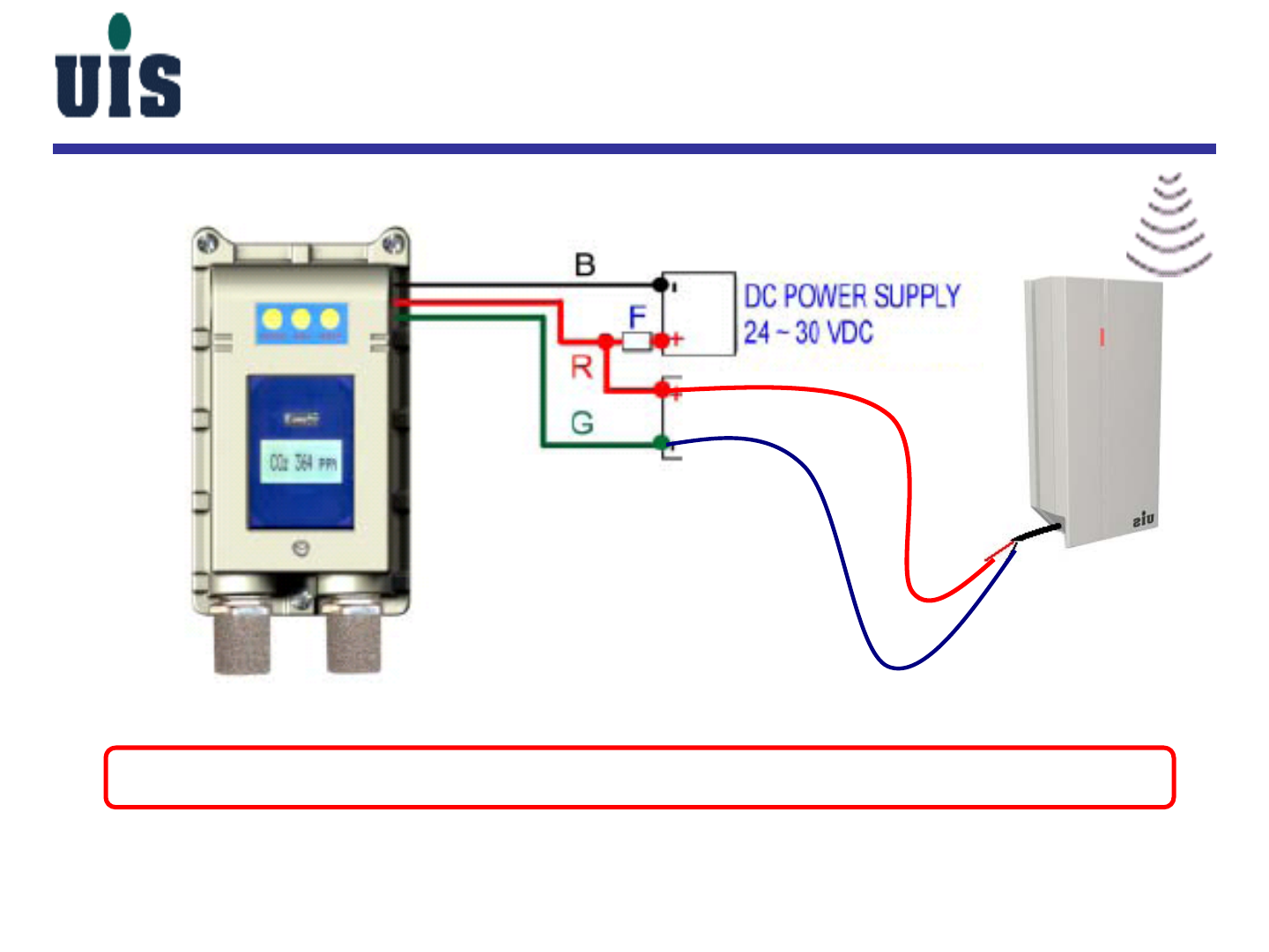
Symbol description:
DC POWER SUPPLY:24VDC ~30VDC。
AI Transducer:To transfer 4 ~ 20 mA current to wireless digital datat。
B:Black wire R:Red wire G:Green wire
F:Fuse GTF200-FL recommend adopt 0.2A or 0.1A Fuse
AI Transducer
+-
4-20mA
Confidential 78
AI/DI Transducer Applications
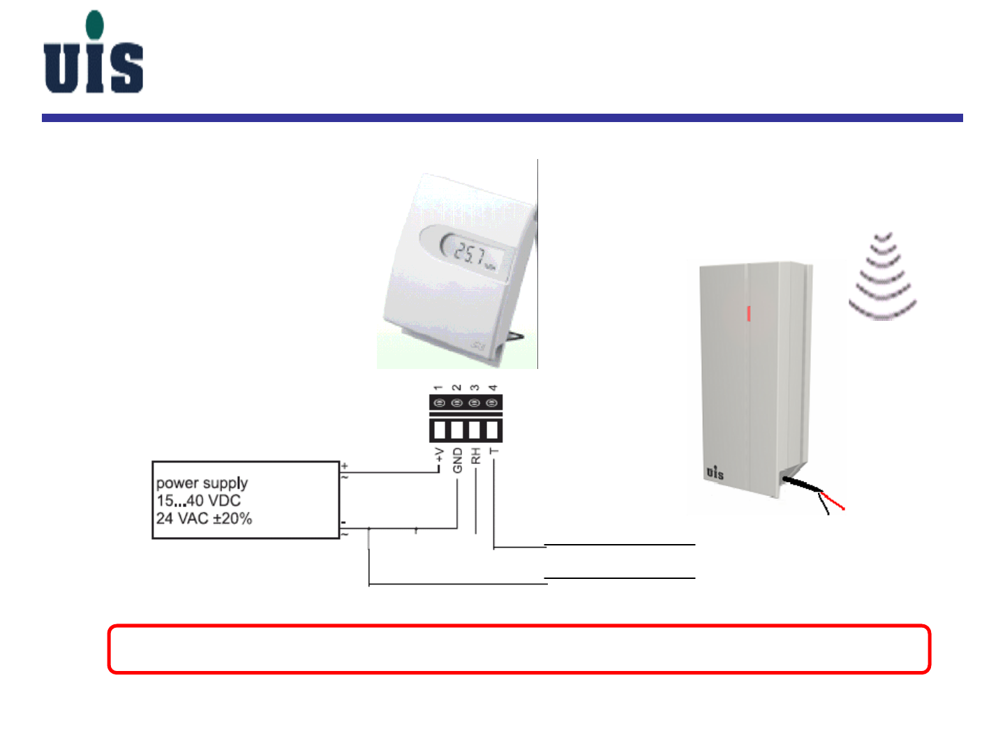
To transform the Temperature Sensor signal into wireless control signal by
using AI Transducer(4-20mA).
4-20mA current
AI Transducer
+
-
Confidential 79
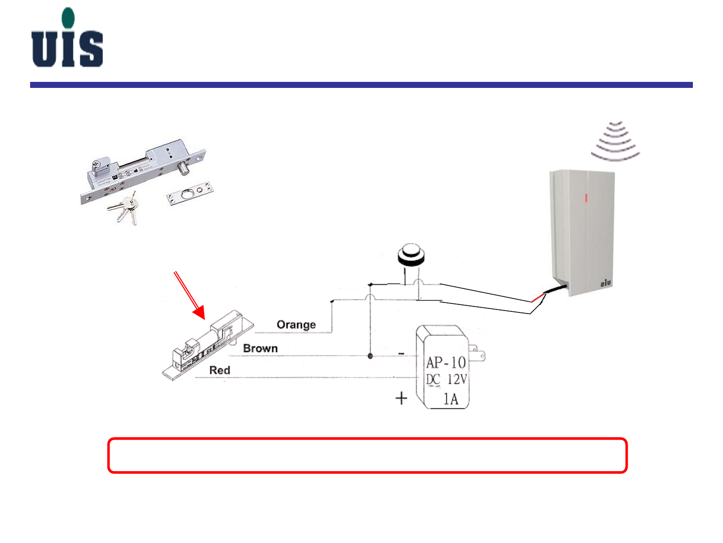
AI/DI Transducer Applications
Electric Lock
manual button switch
WLC-110
To transform a conventional Electric Lock signal into wireless
control signal by Lock Controller
+-

CAUTION
RISK OF EXPLOSION IF BATTERY IS REPLACED
BY AN INCORRECT TYPE.
DISPOSE OF USED BATTEIES ACCORDING
TO THE INSTRUCTIONS
Confidential 80

Confidential 81
FEDERAL COMMUNICATIONS COMMISSION INTERFERENCE STATEMENT This equipment has been tested and
found to comply with the limits for a Class B digital device, pursuant to Part 15 of the FCC Rules. These limits are
designed to provide reasonable protection against harmful interference in a residential installation. This equipment
generates, uses and can radiate radio frequency energy and, if not installed and used in accordance with the
instructions, may cause harmful interference to radio communications. However, there is no guarantee that interference
will not occur in a particular installation. If this equipment does cause harmful interference to radio or television
reception, which can be determined by turning the equipment off and on, the user is encouraged to try to correct the
interference by one or more of the following measures: – Reorient or relocate the receiving antenna. – Increase the
separation between the equipment and receiver. – Connect the equipment into an outlet on a circuit different from that
to which the receiver is connected. – Consult the dealer or an experienced radio/TV technician for help.
CAUTION: Any changes or modifications not expressly approved by the party responsible for compliance could void the
user's authority to operate the equipment.
RF exposure warning ·
This equipment must be installed and operated in accordance with provided instructions and the antenna(s) used for
this transmitter must be installed to provide a separation distance of at least 20 cm from all persons and must not be
co-located or operating in conjunction with any other antenna or transmitter. End-users and installers must be provide
with antenna installation instructions and transmitter operating conditions for satisfying RF exposure compliance.
Canada Warning "Industry Canada regulatory information Operation is subject to the following two conditions: (1) this
device may not cause interference, and (2) this device must accept any interference, including interference that may
cause undesired operation of the device. "The user is cautioned that this device should be used only as specified within
this manual to meet RF exposure requirements. Use of this device in a manner inconsistent with this manual could
lead to excessive RF exposure conditions."

Confidential 82
The End