United Integrated Services ZBM-220 ZigBee Module User Manual
United Integrated Services CO., LTD. ZigBee Module
User Manual

UIS
1 | P a g e
User Manual
ZBM-220

UIS
2 | P a g e
Contents
Certification Notices
1. Overview
2. Specification
3. Pin Assignment

UIS
3 | P a g e
Certification Notices
FCC Compliance Statement
This equipment has been tested and found to comply with the limits for a Class B digital
device, pursuant to Part 15 of the FCC Rules. These limits are designed to provide
reasonable protection against harmful interference in a residential installation. This
equipment generates, uses and can radiate radio frequency energy and, if not installed
and used in accordance with the instructions, may cause harmful interference to radio
communications. However, there is no guarantee that interference will not occur in a
particular installation. If this equipment does cause harmful interference to radio or
television reception, which can be determined by turning the equipment of f and on, the
user is encouraged to try to correct the interference by one or more of the following
measures:
-- Reorient or relocate the receiving antenna.
-- Increase the separation between the equipment and receiver.
-- Connect the equipment into an outlet on a circuit different from that to which
the receiver is connected.
-- Consult the dealer or an experienced radio/TV technician for help.
CAUTION:
Any changes or modifications not expressly approved by the party responsible for
compliance could void the user's authority to operate the equipment.
Labeling requirements
This device complies with part 15 of the FCC Rules. Operation is subject to the following two
conditions: (1) This device may not cause harmful interference, and (2) this device must accept any
interference received, including interference that may cause undesired operation.
FCC RF Radiation Exposure Statement:
This equipment must be installed and operated in accordance with provided instructions and the
antenna(s) used for this transmitter must be installed to provide a separation distance of at least 20
cm from all persons and must not be co-located or operating in conjunction with any other antenna
or transmitter. End-users and installers must be provided with antenna installation instructions and
transmitter operating conditions for satisfying RF exposure compliance.

UIS
4 | P a g e
Information for the OEMs and Integrators
The following statement must be included with all versions of this document supplied to an OEM or
integrator, but should not be distributed to the end user.
This device is intended for OEM integrators only. Please see the full Grant of Equipment document
for other restrictions. This device must be operated and used with a locally approved access point.
Information To Be Supplied to the End User by the OEM or Integrator
The following regulatory and safety notices must be published in documentation supplied to the end
user of the product or system incorporating an adapter in compliance with local regulations.
Host system must be labeled with "Contains FCC ID:XBTZBM-220, FCC ID displayed on the label.
The label text should be updated according to the table shown in Ordering Guide section of this
document.

UIS
5 | P a g e
1. Overview
ZMB-220 is a wireless communication modem based on IEEE802.15.4, which can be
widely used in home automation and security, automatic meter reading, factory automation,
toys and so on.
2. SPECIFICATION
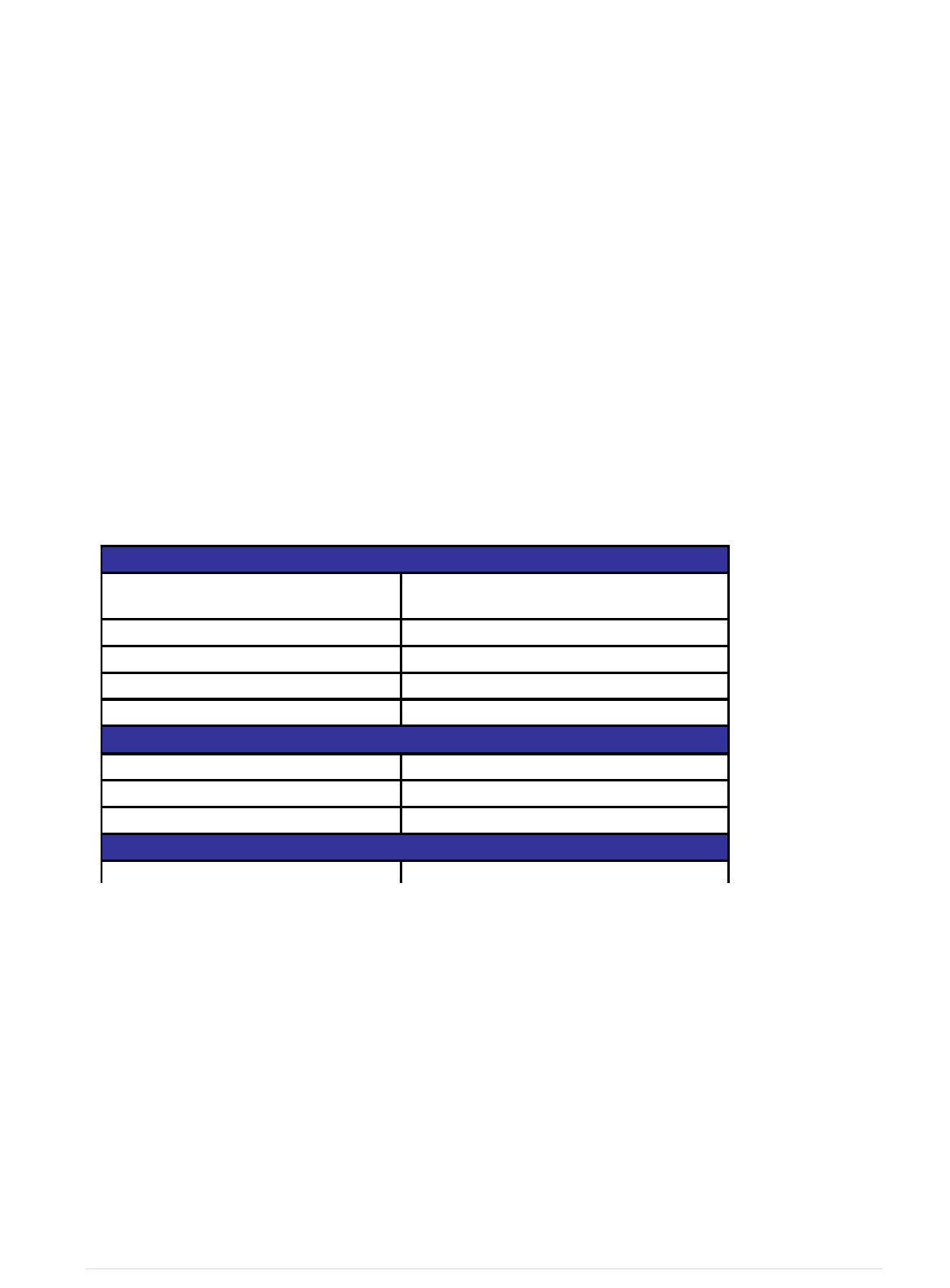
General Specification
Specification
Transmit Frequency 2405MHz to 2480MHz
Modulation OQPSK
Programmable Output Power Up to 4.5 dBm
Operation Voltage 2.0V~3.6V
Environmental
Operating Temperature -10°C to 70°C
Storage Temperature -40°C to 85°C
Humidity 90% RH Max., Non-Condensing
Mechanical Specification
Dimension (WxHxD, mm) 26.2 x 2.0 x 16.5
2.4-GHz IEEE 802.15.4 Compliant RF
Transceiver

UIS
6 | P a g e
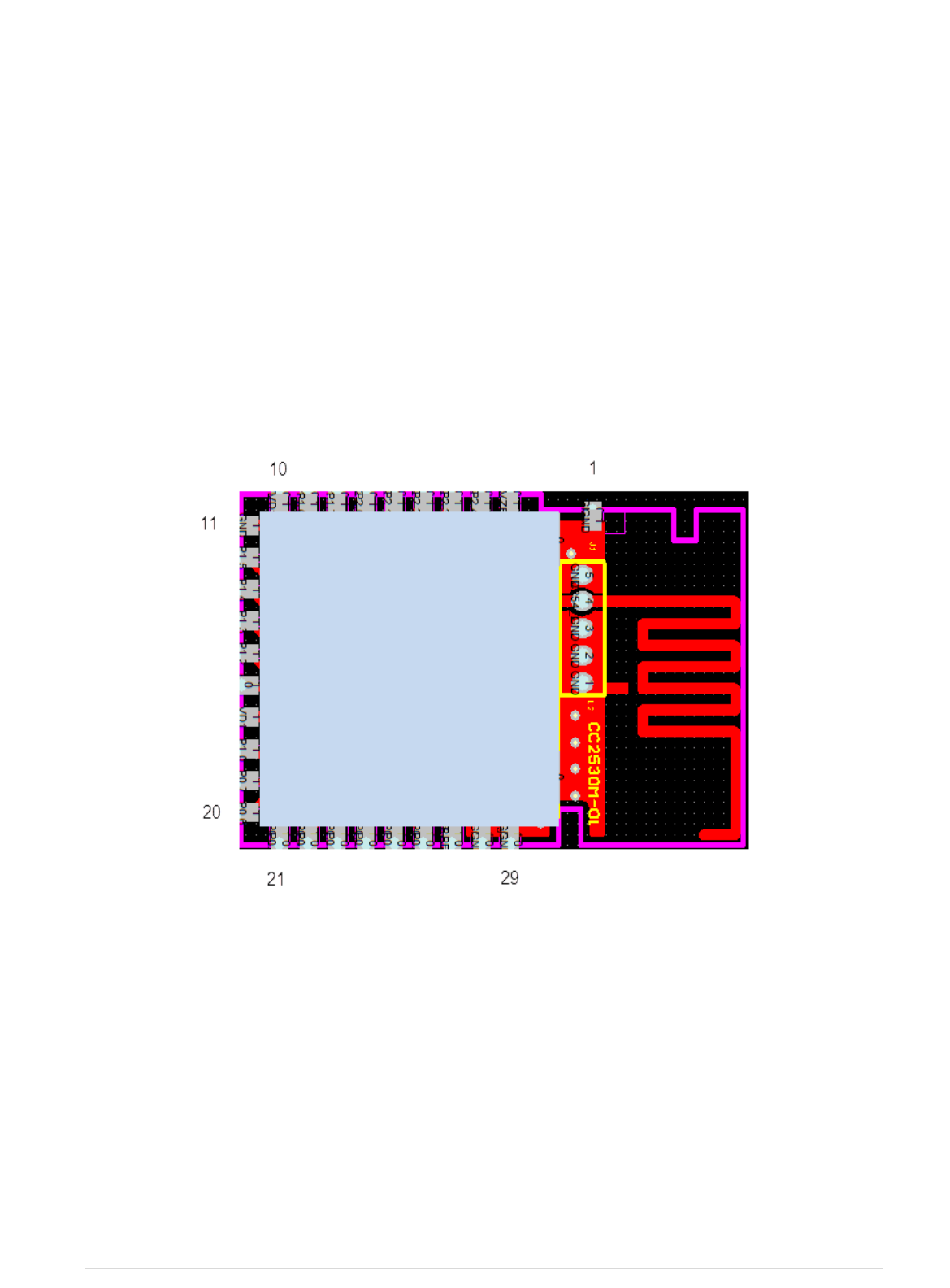
3. Pin Assignment

UIS
7 | P a g e
Pin Name Description Direction
1 GND Power Ground I
2 AVDD DC input(+2.0 ~3.6V) I
3 Port 2.4/32.768 kHz XOSC I/O
4 Port 2.3/32.768 kHz XOSC I/O
5 P2_2 Port 2.2 I/O
6 P2_1 Port 2.1 I/O
7 P2_0 Port 2.0 I/O
8 P1_7 Port 1.7 I/O
9 P1_6 Port 1.6 I/O
10 VDD DC input(+2.0 ~3.6V) I
11 GND Power Ground I
12 P1_5 Port 1.5 I/O
13 P1_4 Port 1.4 I/O
14 P1_3 Port 1.3 I/O
15 P1_2 Port 1.2 I/O
16 P1_1 I/O
17 VDD DC input(+2.0 ~3.6V) I
18 P1_0 I/O
19 P0_7 Port 0.7 I/O
20 P0_6 Port 0.6 I/O
21 P0_5 Port 0.5 I/O
22 P0_4 Port 0.4 I/O
23 P0_3 Port 0.3 I/O
24 P0_2 Port 0.2 I/O
25 P0_1 Port 0.1 I/O
26 P0_0 Port 0.0 I/O
27 RESET_N Reset, active-low I
28 GND Power Ground I
29 GND Power Ground I
P2_4/XOSC3
2K_Q1
P2_3/XOSC3
2K_Q2
Port 1.1 – 20-mA drive
capability
Port 1.0 – 20-mA drive
capability