United Technologies Electronic Controls TSTWHA01 Cor 5C Thermostat User Manual Sentinel Installation Instructions
United Technologies Electronic Controls Inc. Cor 5C Thermostat Sentinel Installation Instructions
Cor 5-7 Installation Manual DRAFT
1
TSTPHA01,
TSTWHA01,
TSTPRH01,
TSTWRH01
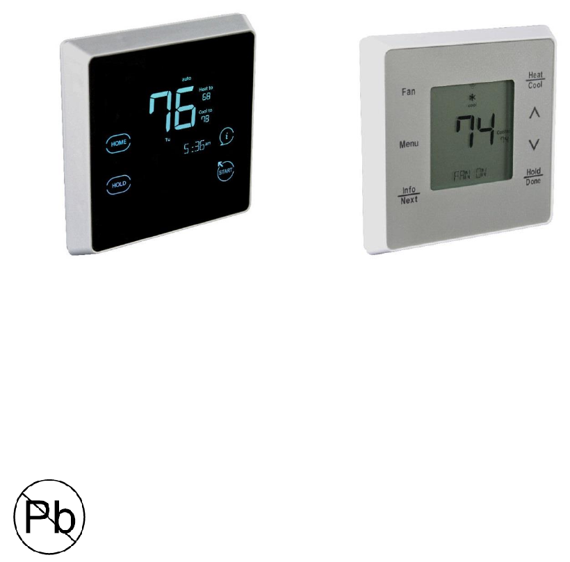
Côr® 5
Côr® 5C
Côr® 7
Côr® 7C
Residential Thermostats
Installation Instructions
Côr® 7 non-Wi-Fi, Côr® 5 Non-Wi-Fi
Côr® 7C Wi-Fi Series Côr® 5C Wi-Fi
(Humidity Control) (No Humidity Control)
Designed in the USA.
NOTE: Read the entire instruction manual before starting the installation.

2
Table of Contents
SAFETY CONSIDERATIONS ...................................................................................................... 2
INTRODUCTION .......................................................................................................................... 2
INSTALLATION CONSIDERATIONS ........................................................................................ 3
INSTALLATION ........................................................................................................................... 5
SYSTEM START-UP AND CHECKOUT .................................................................................. 27
OPERATIONAL INFORMATION.............................................................................................. 32
TROUBLESHOOTING ................................................................................................................ 35
LIST OF WIRING DIAGRAMS .................................................................................................. 38
WIRING DIAGRAMS ................................................................................................................. 39
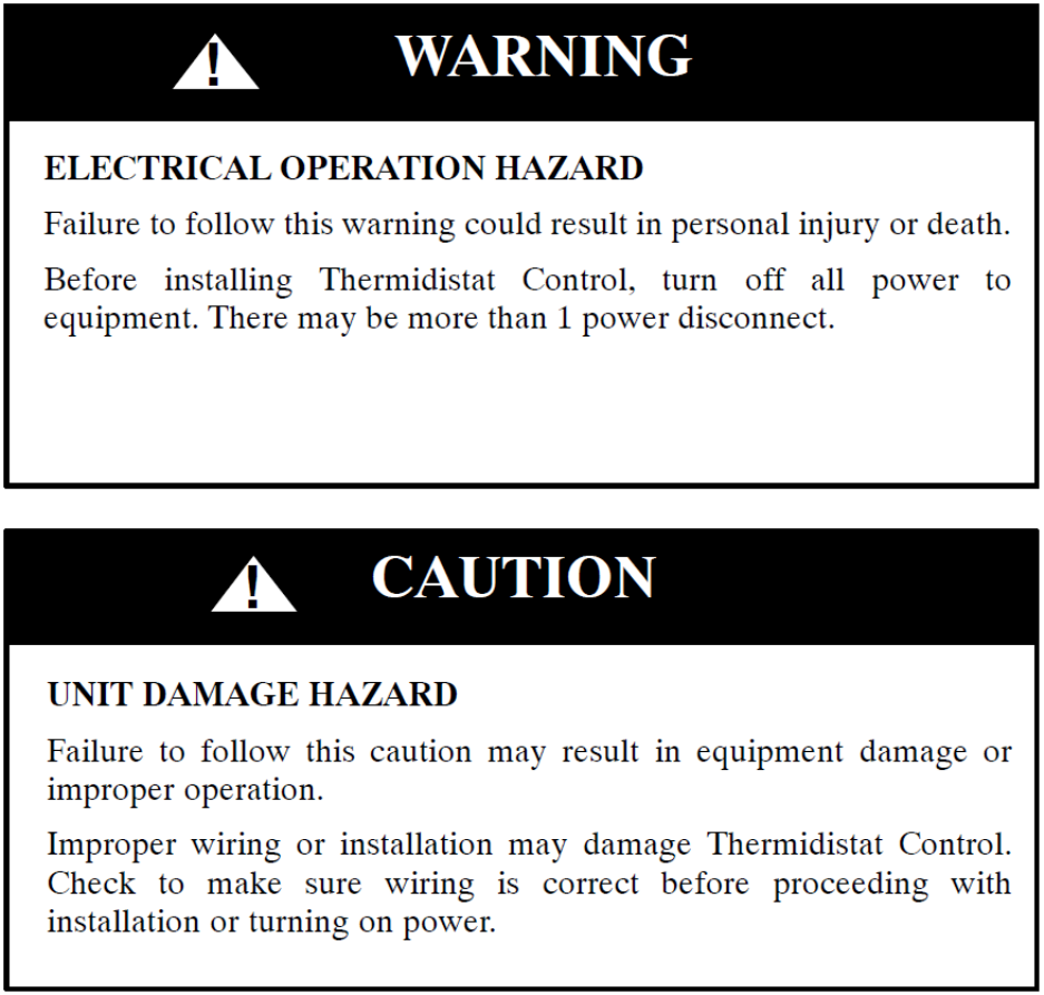
SAFETY CONSIDERATIONS
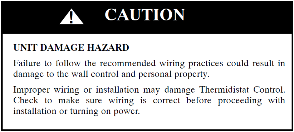
Read and follow manufacturer instructions carefully. Follow all local electrical codes during
installation. All wiring must conform to local and national electrical codes. Improper wiring or
installation may damage the Thermostat.
Recognize safety information. This is the safety--alert symbol When you see this symbol
on the equipment and in the instruction manual, be alert to the potential for personal injury.
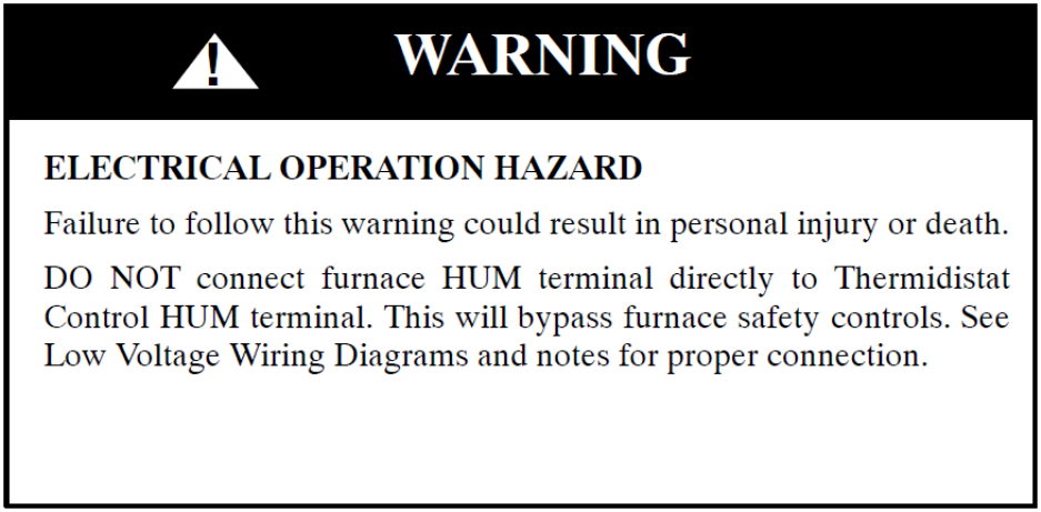
Understand the signal words DANGER, WARNING, and CAUTION. These words are used
with the safety--alert symbol. DANGER identifies the most serious hazards which will result in
severe personal injury or death. WARNING signifies a hazard which could result in personal
injury or death. CAUTION is used to identify unsafe practices which may result in minor
personal injury or product and property damage. NOTE is used to highlight suggestions which
will result in enhanced installation, reliability, or operation.
INTRODUCTION
The Côr 5 series and Côr 7 series thermostat models are 7-day, 5/2-day, 1-day programmable
control is a wall-mounted, low-voltage controls. The Côr 7 and Côr 7C combines temperature
and humidity control in the units. The Côr Thermostats have no need for batteries to store user-
configured settings in memory. During power loss its internal memory saves settings for
unlimited time, and the clock continues to run for at least 24 hours.
A Two-Wire Relay Module option for the Côr 7 series thermostats allows them to connect to a
system using only two thermostat wires at the wall. The Two-Wire Relay Module is located near
the equipment and two wires are used between the thermostat and the Two-Wire Relay Module.
3
In the Côr thermostat programmable configuration, different heating and cooling setpoints and
times are programmable for 4 periods per day or 2 periods per day. Programming can be done for
7 days per week, 5/2 days per week, or 1 day. The programmable thermostat can also be user
configured as a non-programmable thermostat. When operating as non-programmable, the Côr
Thermostat will still have temperature control and in the Côr 7 series, humidity control. The Côr
7 series Thermostat features Touch-N-Go® settings for quick and easy temperature change
without complicated programming schedules.
INSTALLATION CONSIDERATIONS
Power
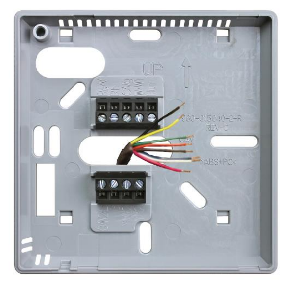
This Thermostat is powered by 24VAC only. It requires 24VAC (Rh and/or Rc and C terminals)
of the low-voltage transformer to be connected to it for proper operation. It will not operate
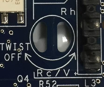
without these 2 connections. Rh and Rc are connected via PCB breakout jumper. See Fig. 1. For
applications using two 24VAC transformers, one in the indoor unit and one in the outdoor unit,
connect the common from each to the C terminal. Connect R from the indoor unit to the Rh
terminal. Connect R from the outdoor unit to the Rc terminal. Then, break jumper on the circuit
board (fig. 1). The W and HUM signals are taken from the Rh power and the G signal is taken
from the Rc power. If Thermostat has been installed in a two--transformer application that is
later changed to a single--transformer installation, installer must install a field supplied jumper
between Rc and Rh. Depending on the installation, up to 14 wires may be required. Installation
with the Two-Wire Relay Module is recommended. Only 2 wires are required for connection
between the thermostat on the wall and the Two-Wire Relay Module. These two wires (V+ and
Vg) do not provide ordinary 24VAC. They carry a combination of power and communications
data that is unique to these products.
Fig. 1 -- PCB Breakout Jumper
Models
The Côr 5 and Côr 5C models are temperature control only and the Côr 7 and Côr 7C are
temperature and humidity control. All 4 can be configured for AC or HP, 1 or 2-speed
4
compressor, and for Hybrid Heat installations. These thermostats may be configured as non-
programmable if user desires.
Humidify Equipment and Connections
The humidify output connects directly to 24VAC operated humidifiers. An isolation relay may
be required when using powered humidifiers. No other connection or interlock is required. Any
of several installer-selectable operating modes are available.
Why delete the warning?
Dehumidify Equipment and Connections
On the two-wire relay option see (Insert the Title of those instructions here). The dry contact
output connects to the dehumidify input on variable—speed furnaces and fan coils. Additional
dehumidification is done by controlling the compressor. A variety of operating modes are
available. The dry contact must be configured for dehumidification in setup SW19. See Wiring
Diagrams for more information.
Outdoor Temperature Sensor (TSTATCCSEN01--B)
Outdoor air temperature sensor is a separate accessory for units installed with the Two-Wire
Relay Module. Optimum performance is obtained when an outdoor temperature sensor is used
with the Côr 7 series thermostat. Plan installation so that 2 wires can be run from the Two-Wire
Relay Module to an outdoor location, preferably on the north side of the house or refer to
Installation Instructions included with the outdoor temperature sensor for simplified connection.
The sensor can be mounted to the outdoor unit and existing control wires may be used for its
connection. Details are provided in sensor instructions.
Remote Indoor Temperature Sensor
A remote temperature sensor may be used with the Two-Wire Relay Module, where it is
desirable to install the Côr 7 series thermostat in a limited access location while measuring the
temperature in the living space. The remote room sensor may be used as a standalone or
averaged with the thermostats local sensor.
5
Wiring
For all wiring applications, use 22 AWG or larger wire. Continuous wire lengths over 100 ft.
(30.5 m) should use 20 AWG or larger. Wire lengths are not to exceed 250 ft. (76 m) per run.
INSTALLATION
Installation Notes:
No part of the Thermostat should be installed directly outdoors or in a cabinet outdoors.
Never remove the thermostat board from the plastic housing. Doing so could warp and
damage the components on the board.
The mounting plate should be mounted to the wall before wires are attached.
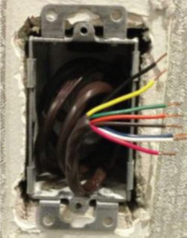
During thermostat installation, provide sufficient excess wiring behind the mounting
plate. Coil the wiring, creating a service loop, and place in mounting box or behind the
wall to remove strain against the terminal strip. See Fig. 2.
6
Fig. 2 -- Coil Excess Wiring
Carton contains the following components.
1. Thermostat (Côr 5 or 7 series)
2. Screws(2)
3. Anchors (2)
4. Quick start guide
5. Installation instructions
Thermostat Location
The thermostat should be mounted:
Approximately 5 ft. (1.5m) from floor.
Close to or in a frequently used room, preferably on an inside partitioning wall.
On a section of wall without pipes or duct work.
The thermostat should NOT be mounted:
Close to a window, on an outside wall, or next to a door leading to the outside.
Exposed to direct light or heat from a lamp, sun, fireplace, or other temperature-radiating
objects which could cause a false reading.
Close to or in direct airflow from supply registers and return-air registers.
In areas with poor air circulation, such as behind a door or in an alcove.
Install Thermostat
7
1. Turn off all power to equipment.
2. If an existing thermostat is being replaced:
a. Remove existing Thermostat from wall.
b. Disconnect wires from existing thermostat, 1 at a time.
c. As each wire is disconnected, record wire color and terminal marking.
d. New or additional wires may be needed to accommodate C wire or added humidity
output on Côr 7 series.
e. Discard or recycle old Thermostat.
8
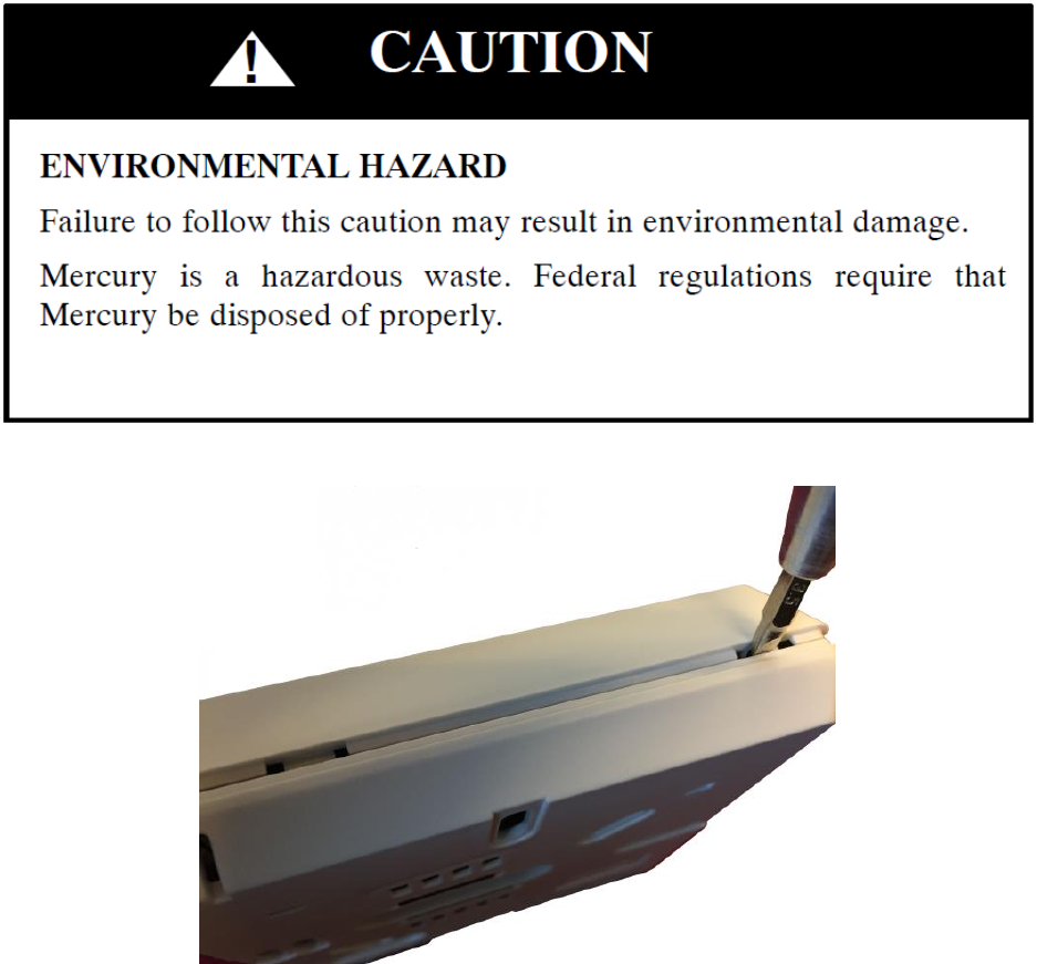
Fig. 3 –Release Tabs to Remove Backplate
1. Use a small screwdriver to release tabs when removing the backplate (Fig. 3).
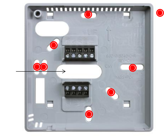
2. Route wires through large hole in mounting base. Level mounting base against wall
(for aesthetic value only—Thermostat need not be leveled for proper operation) and
mark wall through mounting holes. With the additional mounting holes you might be
able to reuse existing mounting locations.
9
Fig. 4 -- Backplate Mounting
3. Drill 3/16--in. mounting holes in wall where marked. Thermostat may be mounted to a
standard junction box, if desired. Hole pattern on the Thermostat mounting base matches
junction box mounting holes.
4. Secure plastic mounting base to wall with screws and anchors provided. Use 2 screws
and 2 anchors provided for a secure attachment. Make sure all wires extend through hole
in mounting base.
5. Adjust length and routing of each wire to reach proper connector block and terminal on
mounting base with 1/4--in. (6 mm) extra wire.
6. Match and connect equipment wires to proper terminals of each connector block, being
careful not to over tighten the screws.
Wire Holes
Mounting Holes
10
A07166
Fig. 5 -- Secure Wires to Terminal Strip
7. Push any excess wire into wall and against mounting base. Seal hole in wall to prevent air
leaks. Leaks can affect operation and cause incorrect temperature and/or humidity
measurement.
8. Reattach thermostat front to mounting base by first setting on at top of mounting base and
then push bottom corners of Display Module to snap into place. See Fig. 11.
11
Fig. 6 -- Attach Display to Backplate
9. Turn on power to equipment. On power up, all display segments will light for 5 sec. and a two
digit code appears on the center of the display which identifies the thermostat equipment type
configuration.
a. A1 — 1--stage air conditioner with furnace or fan coil
b. H1 — 1--stage heat pump with fan coil
c. A2 — 2--stage air conditioner with furnace or fan coil
d. H2 — 2--stage heat pump with fan coil
e. h1 — Hybrid Heat system with 1--stage heat pump
f. h2 — Hybrid Heat system with 2--stage heat pump
g. HT — heating only system
h. CL — cooling only system
Set Thermostat Configuration
Configuration options enable the installer to configure the Thermostat for a particular
installation. Most are not presented to the homeowner and therefore must be properly set by the
installer. (Only those marked with an asterisk * below are available to the homeowner.) The
homeowner configurations are described in the owner’s manual. A special procedure allows
entry into the configuration mode. Selections can be made while in configuration mode.
Description of each selection and how to use the configuration mode follows (See page xx).
12
There are two ways to perform Installer Setup
1. Through the menus on the thermostat.
2. Using a Smart Device to setup the thermostat.
1. Installer Setup using the thermostat
TO ENTER CONFIGURATION MODE
Press and hold MENU button for approximately 5 sec.
Note: Thermostat will automatically exit this mode if no button is pressed for 3 minutes.
Pressing the DONE (Côr 5 series) or START (Côr 7 series) button will exit configuration
mode immediately.
WHILE IN CONFIGURATION MODE
Press UP/DOWN button to select which option to MODIFY. Option will flash while it is active.
(CONFIGURATION OPTIONS – DESCRIPTION SUMMARY See page xx).
Once option is selected press NEXT to activate option values. Option values will flash
when active.
Use UP/DOWN to change the values of the option.
Press DONE (Côr 5 series) or START (Côr 7 series), once all necessary options have
been modified, to exit.
Note: All changes made are saved at the time of selection and will be saved in the event
of the 3 minute time-out or when installer exits from the configuration menu.
Configuring Wi-Fi from the thermostat
From the thermostat control, press START to get to the home screen on the Côr 7C.
Select MENU
UP/DOWN until Wi-Fi is blinking
Press NEXT on Côr 5C or SELECT on Côr 7C
Press UP/DOWN to until Wi-Fi Enable is blinking
o Press Next on Côr 5C or SELECT On Côr 7C
o Press UP/DOWN to change from ENABLED Or DISABLED
Press MENU to go back.
Continue to use up/down arrows to scroll through the options to select Wi-Fi Scan List or
manually set the Wi-Fi Name (SSID).
Note: Wi-Fi names and passwords are case sensitive. When editing names or passwords,
extra characters can be removed by replacing them with a blank space. The alpha
numeric list is in this order when pressing the UP arrow: lowercase, uppercase, blank
space, special characters then numbers when pressing the UP arrow. Order reversed when
pressing the DOWN arrow.
13
Enter Router PSK. (Enter router password using UP/DOWN arrows and NEXT.)
Note:All other options are only required if you want to set it up differently due to specific
advanced router options.
Press DONE on the Côr 5C to exit and save. Press START on the Côr 7C to exit and
save.
2. Configuring Thermostat and Provision Wi-Fi Using a Smart Device
From the thermostat control, press START to get to the home screen on the Côr 7C.
Select MENU
Press UP/DOWN until Wi-Fi is blinking
NEXT
UP/DOWN until 05 Easy Setup
NEXT
UP/DOWN to Enable Easy Setup
Wait for about 10 seconds
On your smartphone, look for available Wi-Fi connections
Connect to “Cor5/7 S/N <serial number>” (Example: Cor5 S/N CEC79F2E1C2)
Enter Password: 12345678
You should see a Wi-Fi connection established with the thermostat.
Open a web browser and type in the URL: mycor5.com. The Commissioning Main Page
will be displayed.
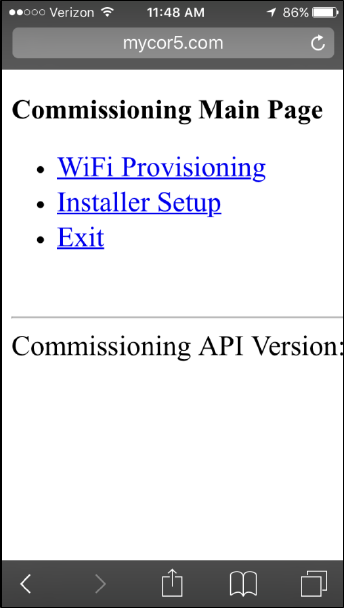
14
Wi-Fi Provisioning and Installer Setup can be done by navigating the menu.
After all settings have been made, check “Connect to Router after Submit” and press the
SUBMIT button. The thermostat will automatically disconnect from the smartphone and
connect to the router.
Verify the thermostat is connected to the router
Select MENU
UP/DOWN until Wi-Fi is blinking
NEXT
UP/DOWN until Wi-Fi Status is blinking
o No connect – thermostat not connected to router
o To Router – thermostat is connected to router but not connected to the server
o To Server – thermostat is connected to the server
Register the thermostat (Associate the thermostat with the mobile app)
From an Android device go to the Play Store or from an Apple device go to the App
Store. Search and Download the “Côr 5C/7C Thermostat” app.
When you first open the app you will be asked if you have the thermostat already
running. If you haven’t gone through setup process on the thermostat, select “No”. If you
have, select “Yes” and proceed.
15
After a Wi-Fi connection has been established, it’s time to create an account to register
your Côr 5C or Côr 7C Wi-Fi, or add another thermostat to your existing account.
Once the thermostat has been connected to your Wi-Fi network record the four digit
registration code that appears on the thermostat display.
To find this code:
o Select MENU
o UP/DOWN until Wi-Fi is blinking
o NEXT
o UP/DOWN until 06 Account PIN
o NEXT
o Thermostat will display “Requesting”
o The account pin will be displayed
Select a new account and enter your email address and create a password (must be at least
8 characters in length), then reconfirm your password and click “Create Web Portal.”
Enter the four digit registration code you recorded earlier and click register.
Congratulations your new Côr 5C/7C Thermostat is now connected to the mobile app! Allowing
you to control the thermostat through your smart device from almost anywhere.
16
CONFIGURATION OPTIONS – DESCRIPTION SUMMARY
Only those marked with an asterisk (*) are available to the homeowner.
SW01 — Equipment Type
SW02 — Clean Filter Timer Adjustment
SW03*— Fahrenheit/Centigrade Selection
SW04 — Fan (G) on with W/W1 Selection
SW05 — Room Air Temperature Sensing (programmable models only)
SW06 — Cooling Lockout Below 55_F/13_C Selection (only available if outdoor air sensor is
present)
SW07 — Zoning
SW08 — Auxiliary Heat Lockout Temperature Setting (only available when heat pump is used
and when outdoor air temperature sensor is present)
SW09 — Heat Pump Lockout Temperature Balance Point (only available when outdoor air
temperature sensor is present)
SW10 — Reversing Valve
SW11 — Adjustable Setpoint Deadband (not available on heat only and cool only systems)
SW12 — Smart Recovery
SW13 — Room Temperature Offset Adjustment
SW14 — Humidity Offset Adjustment
SW15 — Enable Auto Mode
SW16 — Cycles Per Hour
SW17 — Time Between Stages
SW18*— Backlight Configuration
SW19 — Dry Contact
SW20 — Outdoor Air Temperature Offset Adjustment
SW21*— Keypad Lockout
SW22 — High Cool Latch Temperature
SW23 — High Heat Latch Temperature
SW24*— Programmable/Non—Programmable
SW25*— Number of Programmable Periods per Day
SW26 — Minimum Cooling Setpoint
SW27 — Maximum heating Setpoint
SW28 — UV Light Reminder
SW29 — Humidifier Pad Reminder
SW30*— Programmable Fan
SW31*— Daylight Savings Time Configuration
SW32 — Furnace Heat Staging
SW33 — Single or Two--Piece Installation
SW34 — Hybrid Heat Furnace Latch
SW35 — Advanced Smart Setback
SW40 — Fan Humidify
SW41 — Variable Speed Blower
SW42 — Variable Speed Super Dehumidification
SW43 — Intelligent Heat Staging
SW44 — Super Comfort Heat
SW99 — Reset to Factory Defaults
17
Configuration Options - Selection
SW01 —Equipment Type
Range: HP2, AC2, HP1, AC1, hh1, hh2, HT, CL
HP2 — operates a two--speed heat pump with a fan coil
HP1 — operates a single--speed heat pump with a fan coil
AC2 — operates a two--speed AC with a fan coil or furnace
AC1 — operates a single--speed AC with a fan coil or furnace
Hh1 — operates a single--speed heat pump with a furnace
Hh2 — operates a two--speed heat pump with a furnace
HT — operates a heat--only system. Furnace or fan coil only; no outdoor unit.
CL — operates a cool only--system. Outdoor AC unit with an indoor fan coil with no strip
heaters.
Default is H2.
SW02 —Clean Filter Timer
Select number of months before CHECK FILTER is displayed in the text box on the screen.
With OFF selected, the reminder will never come on, disabling this feature. Time selection can
range from 1 to 9 months by selecting numbers 1 through 9. For filter time recommendations,
please consult filter’s Installation Instruction for details.
SW03 —Fahrenheit/Centigrade
Select between Fahrenheit (F) and Centigrade (C) operation.
Factory default is Fahrenheit (F).
SW04 —Fan (G) On With W/W1
This selection determines whether fan (G) output is to be On or OFF when any W/W1 (furnace
or strip heat) output is On. Most furnaces and fan coils manage their own blowers and do not
require separate G signal. For these applications, select OFF. Some auxiliary heaters require
separate G signal to turn on blower. In this case, select On. Select On for geothermal
applications.
Default is OFF
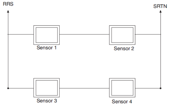
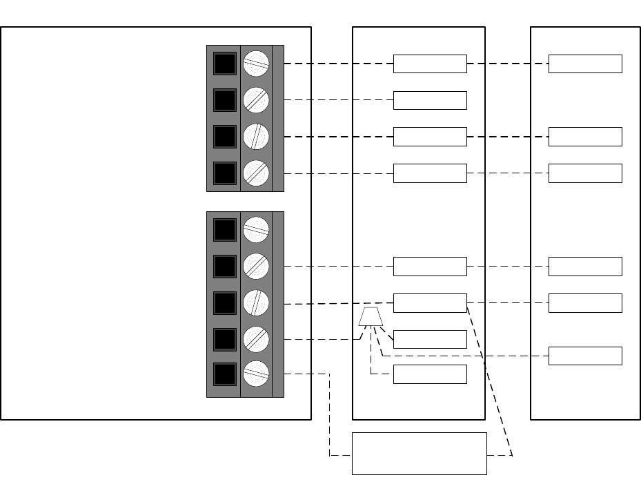
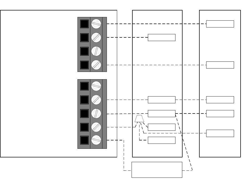
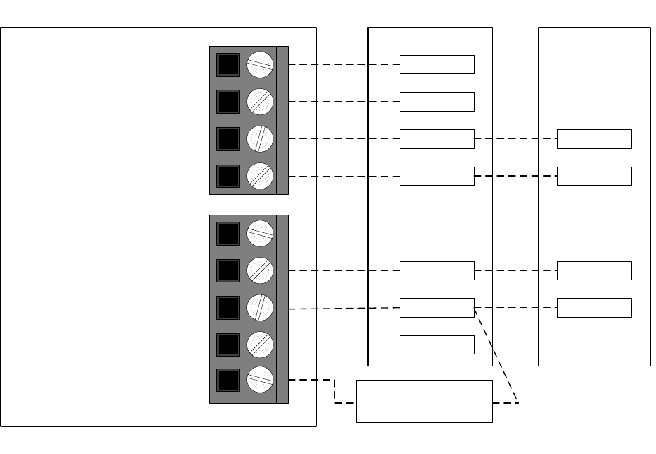
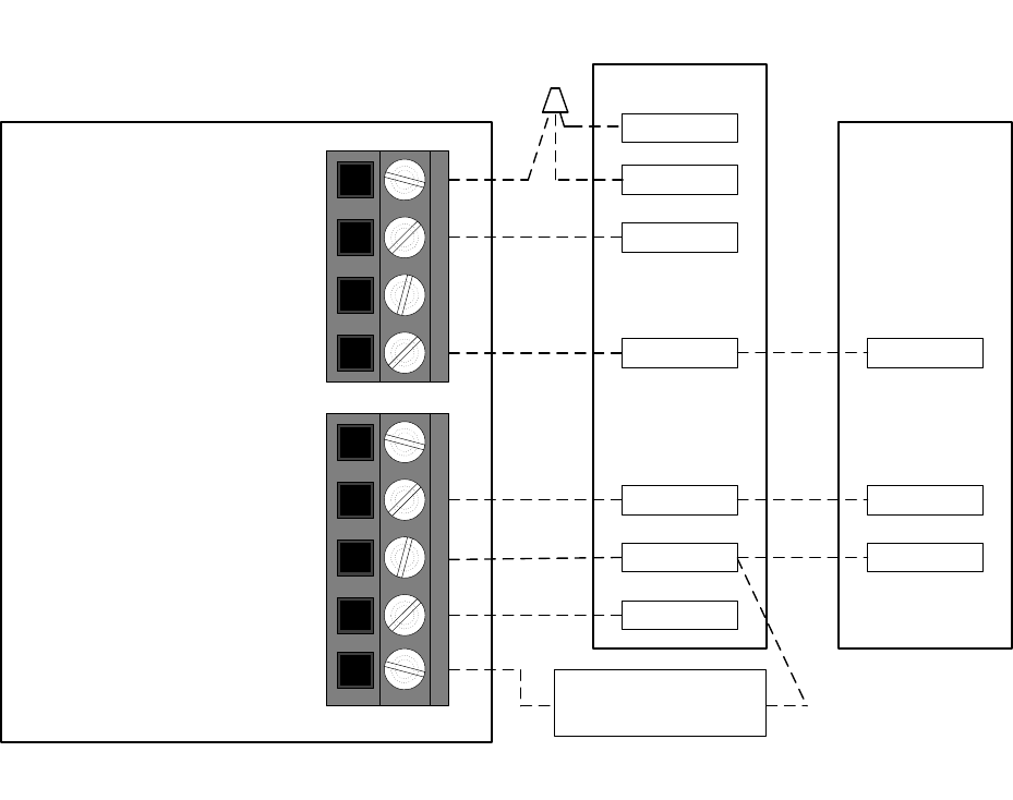
SW05 —Room Air Temperature Sensing (With Two-Wire Relay Module installed)
The remote room sensor may be installed as a single sensor or multiple sensors may be installed
for further averaging functionality. See Fig. 17.
18
A09130
Fig. 17 -- Remote Room Sensor -- Parallel Wiring
This selection determines which sensor the Thermostat will use for measuring room air
temperature. Room air temperature can be sensed in one of three ways; the local sensor (L)
located on the Display Module, the remote room air sensor (r), or the average of local and remote
sensors (Lr). Settings are L, r, Lr.
Default is L.
SW06 —Cooling Lockout Below 55F /13C
This selection disables cooling when outdoor temperature is below 55F /13C. It requires an
outdoor temperature sensor or Wi-Fi connection with internet weather (internet through Wi-Fi is
required and the unit must be registered with location information entered to obtain internet
weather). Setting is not available if valid outdoor sensor is not connected or the thermostat not
receiving internet weather information. Set to OFF to allow cooling below 55F /13C. Set to On
to prevent cooling below 55F /13C.
Factory default is OFF
SW07 —Zoning
This selection should be set to On when the Thermostat is to be used as part of a zoning system.
It is assumed that the zoning equipment will take care of time guard and cycle timers. The
minimum On time is still controlled by the Thermostat.
Default is OFF
SW08 —Auxiliary Heat Lockout Temperature
This selection is available on heat pump systems with a valid outdoor temperature sensor
connected or Wi-Fi connection with internet weather setup. Available settings are: Off, 5, 10, 15,
20, 25, 30, 35, 40, 45, 50, 55.
19
OFF - function is disabled. Auxiliary heat is allowed to operate whenever sufficient demand for
heat is available.
5 to 55F (-15 to 13C) -- Outdoor temperature above which the auxiliary heat is not allowed to
operate (unless MODE is set to Emergency Heat). If room temperature falls below 45F (7C),
the auxiliary heat will be allowed to turn on and will continue to run until demand is satisfied.
Default is OFF
SW09 —Heat Pump Lockout Temperature Balance Point
Only available when heat pump is used and when outdoor air temperature sensor is present or
Wi-Fi connection with internet weather (internet through Wi-Fi is required and the unit must be
registered with location information entered to obtain internet weather).
This selection is only available on Hybrid Heat systems. A Hybrid Heat system is selected via
the SW1 Equipment Type configuration. Configurations settings are: OFF, 5, 10, 15, 20, 25, 30,
35, 40, 45, 50, 55.
OFF — the heating cycle will always start with heat pump heating.
5 to 55F (-15 to 13C) — the outdoor temperature below which heat pump operation is not
allowed.
When emergency heat mode is selected, only auxiliary heat will operate.
Default is OFF
SW10 —Reversing Valve
This selection is only available on heat pump systems. “O” terminal can be configured to be
energized in either heating mode or in cooling mode, depending on heat pump operation. “O” is
used to describe a heat pump system that energizes its reversing valve in cooling. “B” is used to
describe a heat pump system that energized its reversing valve in heating.
H — Reversing valve output (O/W2/B) is energized when HEAT mode is selected.
C — Reversing valve output (O/W2/B) is energized when COOL mode is selected.
Default is C.
SW11 —Deadband Setting Between Heat & Cool
This option is NOT available on Heat Only and Cool Only systems. The selection allows the
installer to choose how much differential exists between the heating and cooling setpoints.
Allowable selections are 1 thru 6.
20
Default is 2.
SW12 —Smart Recovery
Smart Recovery OFF means setpoints change precisely at setback recovery time. 30, 60, or 90
selects the number of minutes recovery starts before programmed recovery time. Recovery takes
place smoothly during the selected recovery time, ending at the recovery time and temperature
which is programmed. Not available when thermostat is configured as non--programmable.
Default is 90
SW13 —Room Air Temperature Offset Adjust
The number of degrees to be added to the displayed temperature to calibrate or deliberately
miscalibrate the measured room temperature (-5 to +5F).
Default is 0
SW14 —Humidity Display Offset Adjust
The percentage to be added to the displayed humidity to calibrate or deliberately miscalibrate the
measured room humidity (-9% to +9% RH).
Default is 0
SW15 —Enable Auto Mode
This selection is not available if the Thermostat is configured as Heat Only or Cool Only in
SW1. This allows the homeowner to select auto changeover mode in addition to heat and cool.
This allows the Thermostat to automatically change between heating mode and cooling mode
when sufficient demand for heating or cooling exists.
ON — Auto mode is available.
OFF — Auto mode is not available.
Default is ON
SW16 —Maximum Cycles Per Hour
This selection limits the number of cycles per hour that the Thermostat allows the system to
operate. Selections are 2, 4, 6.
2 — The heating and cooling outputs will be energized no more than 2 times per hour. When an
output is energized, it will not be energized again for 30 minutes.
4 — The heating and cooling outputs will be energized no more than 4 times per hour. When an
output is energized, it will not be energized again for 15 minutes.
6 — The heating and cooling outputs will be energized no more than 6 times per hour. When an
output is energized, it will not be energized again for 10 minutes.
21
Default is 4.
SW17 —Time Between Equipment Stages
This selection is only available for heat pump systems. This determines the minimum number of
minutes of equipment operation on the highest compressor stage before allowing the transition to
auxiliary heat. Available selections are 10, 15, 20, and 25. The time between stages of any
individual piece of equipment, such as low speed and high speed compressor or fan coil stages,
will be fixed at 10 minutes.
Default is 15.
SW18 – not used
SW19 —Dry Contact Configuration (With optional Two-Wire Relay Module)
There are 3 available selections, OFF, 1 and 2.
OFF — The dry contact is always de--energized.
VENT — The dry contact will be energized for the specified number of minutes per hour. This
selection is programmable by period. When this selection is changed from OFF to VENT,
Ventilation will be available in the homeowners menu under schedule (from the home screen tap
menu, select when schedule is blinking then the up/dn arrow to ventilation). Wake will be shown
above the min/hr. the up/dn arrow will adjust min/hr between 0 and 60. Press Next to move
through the four periods and set the times per period. See Operational Information and Wiring
Diagrams for further explanation of dry contact configuration and use in the Two-Wire Relay
Module installation instructions.
DEHUM — The dry contact will operate as a DH relay. This relay is reverse logic. When the
humidity level is above the dehumidify setpoint, the dry contact D1--D2 will be opened. When
the humidity level is below the dehumidify setpoint, D1--D2 will be closed. There is a +/- 2%
hysteresis around the dehumidify setpoint to prevent rapid on/off cycling of the DH output.
When configured for dehumidification, the Rc terminal must be connected to one of the dry
contact terminals. This provides power to energize the dehumidify terminal on the cooling
equipment when the dry contact is closed. See Wiring Diagrams for more information.
Default is OFF
SW20 —Outdoor Air Temperature Offset Adjustment
This selection allows the calibration, or deliberate miscalibration of the outdoor air temperature
sensor reading. The selection ranges from -5 to +5F.
Default is 0.
SW22 —High Cool Latch Temperature
22
Only available if outdoor sensor is present or Wi-Fi weather is setup for the high cool latch
feature.
This selection is only available when SW1 is set to H2, A2, or h2 and when SW7 (zoning) is set
to OFF. Configuration settings are OFF, 80, 85, 90, 95, 100, 105, 110, On.
OFF — Cooling always starts in low stage (Y1) and stages up to high stage (Y1 and Y/Y2) when
demand is sufficient and staging timer constraints have been satisfied.
80 to 110F (27 to 43C) — Outdoor temperature above which both first and second stages of
the compressor are energized to satisfy all cooling demands. When a cycle starts under a high
cool latch, it will finish the cooling cycle on high stage. If the cooling equipment is energized to
satisfy a dehumidify demand only (no cooling demand), the latch will not be applied.
ON — The Y1 and Y/Y2 outputs are simultaneously energized to satisfy all cooling demands.
Default is OFF.
SW23 —High Heat Latch Temperature (only available if outdoor sensor is
present)
This selection is only available when SW1 is set to H2, or h2 and SW7
(zoning) is set to OFF. Configuration settings are OFF, 20, 25, 30, 35, 40, 45, 50, On.
OFF —Heating always starts in low stage (Y1) and stages up to high stage (Y1 and Y/Y2) when
demand is sufficient and staging timer constraints have been satisfied.
20 to 50F (-7 to 10C) – Outdoor temperature below which both first and second stages of the
compressor are energized to satisfy all heating demands. When a cycle starts under a high heat
latch, it will finish the heating cycle on high stage.
On — The Y1 and Y/Y2 outputs are simultaneously energized to satisfy all heating demands.
Default is OFF
SW24 —Programmable/Non--Programmable
This selection allows the installer to configure the Thermostat as either programmable or non-
programmable. Selections are P, nP.
Default is P.
SW25 —Number of Programmable Periods
This selection allows the installer to configure the Thermostat for two or four periods per day.
Two periods is a common commercial application and four periods is more common for
residential. This selection is not available if SW24 has been set to nP to configure the Thermostat
for non—programmable operation.
23
2 PER — Periods DAY and SLEEP are available
4 Per — Periods WAKE, DAY, EVE, and SLEEP are available.
Default is 4.
SW26 —Minimum Cooling Setpoint
This selection allows the installer to configure the minimum cooling setpoint that the user is
allowed to set. The range is based on the value of the adjustable deadband SW11, such that the
minimum of the range is 50F/10C plus the adjustable deadband and the maximum is
90F/32C.
Default is 52F/11C (based on the adjustable deadband default = 2).
SW27 —Maximum Heating Setpoint
This selection allows the installer to configure the maximum heating setpoint. The range is based
on the adjustable deadband value SW11, such that the minimum of the range is 50F/10C and
the maximum is 90F/32C minus the deadband.
Default is 88F/31C (based on the adjustable deadband default = 2).
SW28 —UV Light Reminder
This selection allows the installer to select the number of months after which the UV Light
reminder will be displayed to indicate to the homeowner that it is time to call the dealer to have
the UV Lights replaced. Selections available are OFF, 6, 12, 18, 24, 30, 36, 42, 48.
OFF — The UV Light reminder is turned off and will never be displayed.
6 - 48 — The number of months after which the UV Light reminder will be displayed.
Default is OFF
SW29 —Humidifier Pad Reminder
This selects the number of months after which the Humidifier Pad Reminder will be displayed.
This is not based on run time.
OFF — The Humidifier Pad Reminder is disabled and will never be displayed.
1-24 — The number of months after which the Humidifier Pad Reminder icon will be displayed.
Default is OFF
SW30 —Programmable Fan
This selection allows the homeowner to program the fan selection to “Auto” or “On” fan
operation for each of the program schedule periods. This selection is only available on
programmable Thermostat
24
OFF — Programmable fan is disabled and the homeowner must manually select “Auto” or “On”
for fan operation.
On — Programmable fan is enabled. The homeowner can program “Auto” or “On” fan operation
along with the heat and cool setpoints for each programmed period. When the program schedule
is running, the programmed heat setpoint, cool setpoint, and fan selection for that period will be
used. If the homeowner “overrides” the programmed fan setting by pressing the fan button, the
override selection will remain in effect until the next programmed period time.
Default is OFF
SW32 —Furnace Heat Staging Control (available only when the
Thermostat is configured to operate AC or A2 equipment).
1 – The Thermostat controls W1 output only and furnace controls the turn on and turn off of
higher stages of heat.
2 – The Thermostat will control the W1 and O/W2/B outputs.
Default is 1.
SW34 -- Hybrid Heat Furnace Latch
This selection allows a Hybrid Heat system to finish a heating cycle using the furnace.
On – Once the furnace is on, it will finish the heating cycle with the furnace. If a heat pump
defrost occurs, the heating cycle will finish with the furnace.
OFF – The system will stage from furnace back to heat pump if heating demand dictates, or 2
minutes after a defrost has ended.
Default is On
SW35 – Advanced Smart Setback
This selection enables the Advanced Smart Setback algorithm.
On – When transitioning from the Away profile to the Home profile, the system will calculate
the amount of time needed to efficiently reach the desired home setpoint on-time.
OFF – When transitioning from the Away profile to the Home profile, the system will ramp
according to the Smart recovery algorithm (30, 60, or 90 minute recovery)
Default is On
SW40 —Humidify Fan
25
This selection controls whether humidification can only be done when a heating demand is
present. If the homeowner turns humidification OFF, this configuration operates as if the
selection was set to OFF.
OFF – The humidity output will only energize when there is a humidity demand and the heating
equipment is energized.
On – The humidity output and the fan will energize anytime humidification is needed during
heating mode regardless of the state of the heating equipment.
Factory default is OFF
SW41 —Variable Speed Blower
This selection allows the installer to select between a single speed or variable motor. In a system
with a two speed compressor (A2, h2, H2), if a dehumidification demand exists and the
compressor is energized for cool to dehumidify, cooling, or both, and the system has a PSC
blower (SW41 = OFF), then both Y/Y2 and Y1/W2 are energized.
OFF – The system has a single speed (PSC) blower.
On – The system has a variable speed blower.
Select OFF for geothermal applications.
Factory default is OFF
SW42 —Variable Speed Super Dehumidification
This option will only be available if the Variable Speed Blower setup (SW41)
has been set to ON.
OFF – The fan output (G) is energized when the compressor is on for cool to dehumidify
functionality.
On – The fan output (G) is de-energized when the compressor is running for cool to dehumidify
functionality. In this setup the fan will run at very low speed because a Y/Y2 or Y1/W2 is
present but the G signal is not. The fan output (G) will be energized any time the compressor is
energized in response to a cooling demand.
Factory default is OFF
SW43 —Intelligent Heat Staging
This function is only available if the equipment configuration is a single speed heat pump (SW01
= HP).
OFF – Electric heat will not be staged.
26
On – Three stages of electric heat will be staged.
This switch should be set to On if the HVAC equipment has two banks of strip heaters. When
electric heat is required, the thermostat will energize the smallest bank first (W1 only), then the
larger bank (turning the smaller bank off -- Y1/W2 only), and then both banks together (both W1
and Y1/W2). When power is cycled to the thermostat, this unit configuration will be displayed as
HS.
Factory defaults is OFF
SW44 —Super Comfort Heat
This option is only available on heat pump units HP (HP, H2, hh, and h2) when SW41 (Variable
Speed Blower) is set to On and the system has a valid outdoor air temperature sensor or Wi-Fi
connection with weather setup
OFF – Comfort Heat is off
On – Comfort Heat feature is on.
If the outdoor air temperature is between 12 to 40F (-11 to 4C) and the compressor is running
in heating, then the fan output is turned off. This will signal the variable speed blower to reduce
the air speed. The fan output is turned off even if the user has the fan selection set to continuous
fan. The fan output will be turned back on in this temperature range if the maximum capacity of
auxiliary heat is on due to system demand (auxiliary heat on in response to a defrost signal
shouldn’t cause the fan to turn back on).
If the outdoor air temperature is below 12F/-11C and there is sufficient demand for the
equipment to be on, then the fan output is turned back on and the W/W1 output is energized. In a
two speed unit the Y/Y2 output should be energized in addition to the W/W1 output. This logic
does not apply to a Hybrid Heat system. In the unlikely event that the installer has selected a heat
pump lockout temperature (SW09) of 5F/-15C in a Hybrid Heat system and the comfort heat
feature is on, then the comfort heat feature will turn the W/W1 on and the compressors off when
the outdoor air temperature drops below 12F/-11C instead of at the lower temperature of 5F/-
15C.
NOTE: All temperature boundaries have a +/- 2 hysteresis
Factory default is OFF
SW99 —Reset to Factory Defaults
Use this capability to reset the Thermostat to “out of the box” conditions. BEWARE! All
configuration settings, program settings, clock, and calendar which have been manually entered
will be lost! When this option is selected, the configuration number (SW99), will appear on the
left and 10 will appear on the right. To perform the reset, first use the NEXT key to move the
box from the SW99 to the 10. Then press and hold the DOWN key. The 10 will start counting
down toward zero. If the DOWN key is kept pressed until the count reaches zero, the reset will
27
be performed. When the value reaches zero, the room air temperature shall display Fd and
“RESETTING..” in the text box. When the factory defaults have been restored, the Thermostat
will act as if power was cycled and return to normal operation. If the DOWN key is released
early, the number will return to 10 and the reset will not occur.
Note: if you reset to factory defaults you will need to reconfigure the thermostat for the
connected equipment. To reset homeowner preferences exit the dealer setup menu and select
menu from the home screen then select settings and go to item 14 “RST DEFAULT” to reset
user preferences.
SYSTEM START-UP AND CHECKOUT
The Thermostat is designed with a built-in installer test capability. It allows easy operation of
equipment without delays or setpoint adjustments to force heating or cooling. To enable installer
test capability called Output Test mode, press and hold the fan button for 10 seconds. Pressing
the Heat/Cool button will change the system operating mode to test the heating and cooling
equipment based on the equipment setup. Auto Mode is not available during Installer Test Mode.
If no buttons are pressed for 15 minutes, the installer test mode will be terminated. Pressing
Heat/Cool mode button will stop the test but remain in Output Test model Pressing DONE or
START at any time will exit installer test mode.
Aux Heat – The first stage of Aux Heat will be energize for three minutes, then the first and
second stages (if a second stage exists) will turn on for an additional three minutes. The Aux
Heat icon at the top of the screen will be displayed and a text message on the screen will display
STG 1 and count down from 180 seconds. After three minutes the thermostat will go back to
Heat/Cool mode to Off. If no buttons are pressed for 15 minutes, the installer test mode will be
terminated.
Heat – The first stage of heating will be energized for three minutes, then the first and second
stages (if a second stage exists) will turn on for an additional three minutes. During the first stage
of heating, the HEAT icon will be displayed along with the text “STG 1”. During the second
stage of heating (if one exists), the “STG 2” text will be displayed if the system has a two-stage
compressor (A2, h2, or H2 unit types). The “auxiliary heat on” icon will be displayed if the
second stage is electric heat (HP unit type). While the heating test is active, the fan output
(accessory output on the Côr 7 series) can be toggled by pressing Menu then the up/dn arrows to
select.
Output Test for cooling is the same as described for heating above. The COOL icon and the
stage text will be displayed during cooling in Installer Test Mode. While the cooling test is
active, the fan output (and accessory output on the Côr 7 series) can be toggled by pressing Menu
then the up/dn arrows to select and toggle them on/off.
TO TEST FAN
28
Fan button switches FAN icon between AUTO and On. While On is displayed, G output will be
energized, turning fan on. On some fan coils, fan continues to operate for 90 sec after G signal is
removed.
Final Settings
Be sure to press DONE or START to exit installer setup mode. If the system is to be left in
operation after installation is complete, use (HEAT/COOL) button to select between HEAT,
COOL, or AUTO to provide desired operation of heating, cooling, or auto. On the programmable
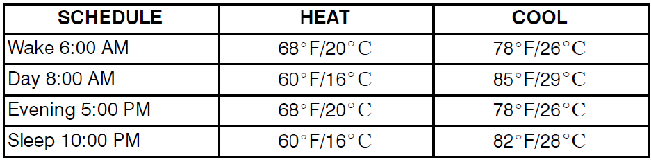
models, the default setpoints and programmed schedule conform to the Energy Starr
requirements of the U.S. Department of Energy for both heating and cooling. These provide
energy saving temperature settings. Refer to Table 1.
Table 1 – Energy Star Default Schedule
If the programmed schedule is to be used, make sure one of the Touch-N-Go icons is visible
without the hold button during idle mode (press start to toggle from active screen to idle screen).
Pressing the HOLD button will display the hold options and then the up/dn arrows will scroll
through options based on current selection. Touching Select will either accept the hold option or
go to the next level of options for that specific hold.
Hold options:
Hold till next period – at the time of the next period the schedule will resume
Hold until time (configurable) after reaching the time entered the schedule will resume
Permeant – keeps the setpoints entered until the user makes a change
Cancel or No Hold – The schedule will resume immediately
The FAN button on the home screen may be used to select between AUTO (fan on only with
equipment) and On (fan on continuously) fan modes. The fan can also be put into “Air
Circulation” mode by selecting Menu > Settings > up/dn arrow until you see Circulation > Select
then up/dn arrow to change minutes per hour. That will allow the user to select the number of
minutes per hour the fan will run even if there is not call for heat or cooling. If the user needs to
have different min/hr of air circulation then they program that under user schedule buy going to
home screen > Menu > Schedule > Circulation.
For further information on temperature selection and programming, refer to Homeowner’s
Guide.
Setting The Clock, Calendar and Schedule
29
To set the clock, press MENU > Next until Settings is blinking the press Select. Use the up/dn
arrows to move to time then press Select. The Clock will be displayed at the bottom of the
screen. Use the up/dn arrows and next button to adjust the time. Setting the date may be changed
by navigating to MENU > Next until Settings is blinking the press Select. Use the up/dn arrows
to move to Date then press Select. The UP/DOWN buttons are used to change the Month, Day,
and Year setting when the numbers are blinking.
To change the schedule, from the home screen press MENU > Schedule then Select > up/dn
arrows to move through the following options to modify.
PROFILES
Wake, Away, Home, Sleep Temperatures
PROGRAM
All days, Weekdays, Weekends, Individual days
NUM PERIODS
2 or 4 Periods
HOLD PREFER
sched | perm | timed
PRGM ENABLE
Enabled / Disabled
CIRCULATION
0 to 60 minutes (steps of 5) per activity
TOUCH-N-GO
Enabled / Disabled
ALL PROGRAM PERIODS (WAKE, AWAY, HOME, SLEEP) MUST OCCUR WITHIN THE
SAME 24 HOUR PERIOD.
Humidity Control Features
The various humidity control features of the Côr 7 thermostat are explained below. They are
grouped into 2 sections, humidification and dehumidification. Instructions on how to select each
feature are given at the end of each section.
Humidification
The Côr 7 thermostat can control a standard 24VAC humidifier to control humidification in the
home. A humidify setpoint between 10 and 44% relative humidity in 2% increments is selected
by the homeowner. When humidity in the home drops below setpoint, humidifier will be turned
on to raise humidity level. See Table 2 for reference.
Table 2 – Humidification Selections
Selection
Humidify Setpoint Range
Normal Humidify
10 – 44% Steps of 2%
Auto Humidify (Window Protect™)
Level 1 - 9
Humidify with Fan
Off, On
Hum Off
Off
To get to settings for Humidity
From the home screen press Menu > Settings > up/dn arrow to get to Humidify > Select then
scroll through options with up/dn arrows.
1. Normal Humidify
30
In normal humidify, the humidifier will be turned on if there is humidity demand and any
heating equipment is on. This will include furnace, heat pump, or auxiliary heat. The
humidifier will only operate when the heating equipment is operating.
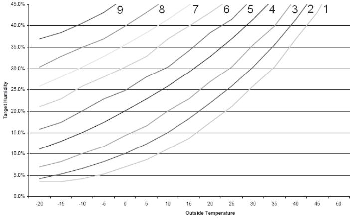
2. Auto Humidify
The Thermostat will automatically adjust the humidity setpoint according to the outdoor
temperature. As the outdoor temperature decreases, the humidity setpoint also decreases.
Settings ranging from 1 to 9 (1 being the lowest and 9 the highest) will be visible to the
homeowner. See Fig. 18 for outdoor temperature/indoor humidity relationship in auto
humidify mode. Outdoor Air Temperature Sensor must be connected or Wi-Fi internet
weather setup.
3. Humidify with Fan
The humidity output and the fan will energize anytime humidification is needed during
heating mode regardless of the state of the heating equipment.
4. Hum Off
This turns off the humidifier operation.
Additional Humidify Comments
The humidifier is actually turned on when humidity is 1% below setpoint and
turned off when it reaches 1% above setpoint. This built--in hysteresis prevents
humidify output from toggling on and off when humidity level is near setpoint.
Dehumidification
Dehumidification is done only during cooling. Depending on type of equipment used,
compressor speed, blower speed, setpoint adjustment, and equipment cycling are modified to
provide added dehumidification. A dehumidification setpoint (separate from humidification
setpoint) is available to the homeowner. It can range from 46% to 66% relative humidity. When
actual humidity is higher than setpoint, a dehumidification demand exists. The Côr 7 Thermostat
responds by activating the dry contact (when enabled in SW19). It may also control the
compressor and blower, depending on equipment type and dehumidify selection choice. The 3
available selections are described below. A mandatory 5 minute blower off delay will be
enforced if there has been a call for dehumidification during a cooling call. The amount of extra
dehumidification available is very dependent on the type of equipment in the home. Without a
variable--speed blower, the system’s ability to adjust dehumidification is very limited.
1. Normal Dehumidify Operation
When normal dehumidify is selected, the compressor will not turn on without a
cooling demand. If dehumidify demand exists while cooling, dry contact will also be
active (24VAC removed). This output commands variable-- speed blowers to reduce
their airflow, which improves water removal from the cooled air.
2. Cool to Dehumidify
The cool to dehumidify selection tells the system to operate the compressor, within
limits, when there is a dehumidify demand even if there is no cooling demand. The
31
limits are that the system may overcool up to 3_, but no more, while attempting to
satisfy a dehumidify demand. Within this 3_ range, there is an additional balance
between overcooling and humidity satisfaction. When overcooling must occur, the
dehumidify setpoint is adjusted upward by 2% per degree of overcooling. For
example, a cooling setpoint of 76_F/24_C and a dehumidify setpoint of 60% is
equivalent to a cooling setpoint of 75_F/24_C and a dehumidify setpoint of 62%. This
dehumidify set 51 point change is internal to the Thermostat and is not shown on the
display.
A06599
Fig. 18 -- Auto Humidity
3. Dehumidify Off
Dehumidification can be turned off completely. This can be done without changing
existing setpoints.
To Select Dehumidification (programmable -- between NORMAL, OVERCOOL, and
OFF)
From the home screen press Menu > Settings > up/dn arrow to get to Dehumidify > Select then
scroll through options with the up/dn arrows.
Additional Dehumidify Comments
Dehumidification can be enhanced (with some efficiency loss) by turning blower off
immediately at the end of each cooling cycle (eliminating normal 90 sec blower off delay).
Where maximum humidity removal is desired, this should be done. Fan coils have the capability
of removing this off delay. On FK or FV Fan Coils, set delay tap to 0/0. On standard fan coils, a
jumper can be cut to disable off delay. Refer to fan coil Installation Instructions for details. If
FAN is set for continuous operation (Fan On selected), G output is turned off for 5 minutes at the
end of each cooling cycle as long as dehumidify demand exists. Like humidify, dehumidify
actions are initiated when humidity is 1% above setpoint and are terminated when humidity
drops to 1% below setpoint. This prevents unnecessary toggling of dehumidify actions when
humidity is near setpoint.
32
Dehumidify Output and Equipment Connections
When there is a dehumidify demand, dry contact is activated, meaning that a 24VAC signal is
removed from the DHUM or DH output terminal. In other words, dehumidify output logic is
reversed -- output is turned On when no dehumidify demand exists and is turned OFF when
demand exists. Carrier FK and FV series variable--speed fan coils, all variable--speed furnaces,
and select single and multi-stage furnaces with the dehumidify connection have dehumidify
inputs which connect directly to Two-Wire Relay Module dry contact. Refer to the furnace
literature for dehumidification options and the Two-Wire Relay Module instructions. The FK
and FV series fan coils have a terminal marked DH which should be connected to the Two-Wire
Relay Module dry contact output. Jumper J1 on fan coil MUST be removed. It is located behind
the DH terminal. Additionally blower delay tap on fan coil should be set to 0/0 (no On delay and
no OFF delay) when using cool to dehumidify. With this selection, the blower stops when G
signal is removed, preventing re-evaporation of water from the coil which would occur during
the normal 90 sec blower off delay. See fan coil installation instructions for more information.
The furnace dehumidify input acts differently depending on which style of variable speed, select
single-stage or multi-stage furnace control you have.
Vacation
A vacation mode is set specifically for times where the home will not be occupied for an
extended period. Vacation mode is created the day your will be leaving as a continuous hold for
more than a day. While in Vacation mode, the system provides temperature and humidity
protection for the home in the selected mode, but not comfort.
Set Vacation Mode
To set vacation mode from the home screen you will use the up/dn arrows to set your desired
temperature, then the hold menu will be displayed. Use the up/dn arrows to scroll to the Hold
until time option. Set the time of day you will return using the next button and up/dn arrows.
Once the time is set the Next button will go to the date. Enter the date you will return then the
final next will take you back to the home screen. To exit vacation mode you can press any of the
Hold button and select resume schedule.
OPERATIONAL INFORMATION
Timers
Five--Minute Compressor Timeguard
This timer prevents compressor from starting unless it has been off for at least 5 minutes. It can
be overridden for 1 cycle by simultaneously pressing FAN and UP buttons.
Cycle Timer
Based on the selection of 2, 4, or 6 cycles per hour, this timer is set to 30, 15, or 10 minutes. This
much time must elapse from the start of one cycle before another cycle can start. It serves to
impose the cycles per hour limits. It can be defeated for one cycle by simultaneously pressing the
FAN and UP buttons.
33
Ten--Minute Staging Timer
In multistage heating or cooling, this timer prevents any higher stage from turning on until
preceding stage has been on for 10 minutes. When staging between compressor and electric heat
or between compressor and furnace heat, the time is configurable. The timer is configurable via
SW17. This timer is overridden if temperature error is greater than 5 (usually due to a large
change in desired temperature) and equipment stages up in 60 second intervals.
The ten--minute staging timer does not require the thermostat to change to a higher stage after 10
minutes. If the system is able to meet the demand (maintain setpoint) it may not change stages
after the 10 minute timer has expired. If there is sufficient demand for a higher stage at the end of
10 minutes or at any time after the 10 minute timer has expired, the thermostat will energize the
next higher stage.
Defrost
When defrost occurs in a Hybrid Heat system, the furnace will operate during the defrost cycle.
At the end of the defrost cycle, the furnace and heat pump will be de-energized while the fan is
energized for 2 minutes allowing the heat exchanger to cool down. If SW34, Hybrid Heat
Furnace Latch is set to Off, at the end of the 2 minute time, the heat pump will be re-energized if
a call for heat still exists. If SW34 is set to On (default), the furnace will remain on until the end
of the heating cycle.
Defrost detection is not available if the installer has configured the O/W2/B output to function as
a B output. During heat pump heating, a defrost signal shall be considered valid if the
compressor output is energized and the defrost signal has been active for less than 15
consecutive minutes. Any defrost signal present for longer than 15 minutes shall be considered
invalid. Heat pump/fan coil and Hybrid Heat systems shall use this input to:
Detect that defrost is in progress and energize the auxiliary heat to provide homeowner
comfort during the defrost cycle
Allow a defrost cycle to run to completion regardless of the system demand
Three--Minute Minimum on Time
In normal operation, when a stage turns on, it will not turn off for a minimum of 3 minutes. In
Hybrid Heat systems, the minimum on time for the furnace is 5 minutes. If the setpoint is
changed, this timer is canceled, allowing the equipment to turn off immediately when the
demand is removed. The 3 minute minimum on timer applies to all stages of heating and cooling,
except Hybrid Heat. A stage will run for a minimum of 3 minutes before the thermostat will be
allowed to stage to a lower stage.
Heat/Cool Setpoints (Desired Temperature)
A minimum difference of 1 and maximum of 6 is enforced between heating and cooling
desired temperatures. This is done by allowing 1 setting to “push” the other, to maintain this
difference. This difference is adjustable via Configuration SW11.
Equipment On Indicators
When cooling equipment is on, a COOL icon is displayed. While cooling equipment operation is
delayed by the time guard or cycle timer, COOL will flash. The same is true for HEAT icon.
34
During second stage compressor operation a “2” will be displayed with the HEAT or COOL
icon. This is displayed when the Thermostat is configured as H2, A2, or h2.
When the W is energized in a heat pump or Hybrid Heat system, the “auxiliary heat” icon will be
displayed.
Auto Changeover
When auto changeover mode is selected, a change from heat to cool (or vice versa) will not
occur until an opposite mode demand has existed for 20 minutes. If setpoint is changed, 20
minute requirement is deleted.
Emergency Heat Mode
When Thermidistat Control is configured as a heat pump and emergency heat is selected, all Y
signals are locked out, and W becomes energized upon a call for heat.
Programmable Fan
The fan output can be programmed based on period of the day. When programming for each day
and period the fan can be set to On or AUTO. If the fan button is pressed to change from On to
Auto or vice versa when programmable fan has been enabled, the manual change will only
remain in effect until the next program period, when the programmable fan setting will be
changed per the scheduled setting.
Dry Contact
On the Côr 7 series thermostats with the optional Two-Wire Relay Module, the dry contact that
can be used for control of an auxiliary device. The dry contact may be configured to be closed
for a specific number of minutes per hour for each period of the program schedule. This can be
used to operate a ventilator, damper, system blower, or other auxiliary device. There are two
terminals, D1 and D2.
On both the programmable and non--programmable models, when configured as a dehumidify
output, it will operate cooling equipment capable of dehumidify function. When configured for
dehumidification, the Rc terminal must be connected to one of the dry contact terminals. The
other dry contact terminal is connected to the dehumidify terminal on the furnace or fan coil.
This provides power to energize the dehumidify terminal on the cooling equipment when the dry
contact is closed.
If it is desired to operate a ventilator or other device, the D1 and D2 terminals can be connected
directly to the equipment. This will provide a closed contact for the specified number of minutes
per hour. See SW19.
If timed control of the system blower is required, the dry contact can be used for this function.
The G terminal can be connected to one of the dry contact terminals with the other terminal
being connected to Rc and/or Rh for timed control of the fan. Note that this is not the same as
programmable fan SW30.
35
See Wiring Diagrams for more information.
Temperature Offset After Power Cycle
To compensate for internal heat build--up from the electronics in the thermostat, the thermostat
will add an offset to the actual temperature that it measures. If the thermostat power is cycled
quickly, one can witness an immediate increase in the actual temperature displayed due to this
added offset. The thermostat display will return to the actual room temperature after several
minutes of operation.
TROUBLESHOOTING
If the display module doesn’t power up after power is applied, check the Rc/Rh and C terminals
for 24VAC. If 24VAC is present, check the voltage between Vg and V+. This voltage will be
approximately 12--20VDC. If voltage is present, check the polarity to make sure it is wired
correctly. The display will not power up if polarity is reversed.
If dashes appear for SW01 in config and during reboot, the problem could be the red pigtail
being wired to Rc or Rh and the black pigtail being wired to C. If so, remove the two--wire
pigtail and connect to the V+ and Vg terminals.
Error Codes
Comm Error -- If the Côr 7 Series Thermostat and the Two-Wire Relay Module cannot
communicate via two-wire connection, an Comm Error will be displayed.
HW Failure -- If Côr 7 Series Thermostat’s internal memory fails, HW Failure will be
displayed. Replace Thermostat.
Invalid HUM -- If Côr 7 Series Thermostat cannot properly read humidity, Invalid HUM will
be displayed. Replace Côr 7 Series Thermostat. If both Humidify and Dehumidify have been set
to OFF, the humidity value will be shown as “----” when viewed from the humidity menu, but no
Invalid HUM will be shown in the display.
Table 4 can be used as a troubleshooting tool for determining which outputs will be active for a
particular configuration and each operating mode. When replacing a failed component such as an
equipment control module or a display module, the installer should replace both parts as a
matched set. It is very easy to accidentally mix an A/C or HP display with a PRH equipment
control module. When this happens, some functions appear in the setup while others do not. This
can be very confusing to troubleshoot. Verify that both parts have the same model and serial
number when troubleshooting the thermostat.
Table 4 – Equipment Configuration Outputs
IDU
ODU
Equip
ment
Type
Options
Cool
Stage
1
Cool
Stage
2
Heat
Stage
1
Heat
Stage
2
Heat
Stage
3
Heat
Stag
e 4
EM
Heat
Stage
1
EM
Heat
Stage
2
1 Stage
1
Opt
--
Y/Y2
--
W/W1
--
--
--
--
--

36
Furnace
Stage
AC
1=AC
Fan Coil
1 Stage
Heat
1
Stage
HP
Opt
1=HP
RVS=O
Opt
10=C
Y/Y2
O/W2
/B
--
Y/Y2
Y/Y2,
W/W1
--
--
W/W1
--
Fan Coil
1 Stage
Heat
1
Stage
HP
Opt
1=HP
RVS=B
Opt
10=H
Y/Y2
--
Y/Y2
O/W2/
B
Y/Y2,
W/W1,
O/W2/
B
--
--
W/W1
--
Fan Coil
1 Stage
Heat
2
Stage
HP
Opt
1=H2
RVS=O
Opt
10=C
Y1/W
2
O/W2
/B
Y1/W
2,
Y/Y2,
O/W2/
B
Y1/W2
Y1/W2
,
Y/Y2
Y1/W2
,
Y/Y2,
W/W1
--
W/W1
--
Fan Coil
1 Stage
Heat
2
Stage
HP
Opt
1=H2
RVS=B
Opt
10=H
Y1/W
2
Y1/W
2,
Y/Y2
Y1/W2
,
O/W2/
B
Y1/W2
,
Y/Y2,
O/W2/
B
Y1/W2
,
Y/Y2,
W/W1,
O/W2/
B
--
W/W1
--
Fan Coil
2 Stage
Heat
1
Stage
HP
Opt
1=HP
RVS=O
Opt
10=C
Y/Y2
O/W2
/B
--
Y/Y2
Y/Y2,
W/W1
Y/Y2,
W/W1,
Y1/W2
--
W/W1
W/W1
,
Y1/W
2
Fan Coil
2 Stage
Heat
1
Stage
HP
Opt
1=HP
RVS=B
Opt
10=H
Y/Y2
--
Y/Y2
O/W2/
B
Y/Y2,
W/W1,
O/W2/
B
Y/Y2,
W/W1,
Y1/W2
,
O/W2/
B
--
W/W1
W/W1
,
Y1/W
2
Fan Coil
3 Stage
Heat
1
Stage
HP
Opt
1=HP
RVS=O
Opt
10=C
Opt
43=On
(3 stage
Heat)
Y/Y2
O/W2
/B
--
Y/Y2
Y/Y2,
W/W1
Y/Y2,
Y1/W2
Y/Y2
,
W/W
1,
Y1/
W2
W/W1
W/W1
,
Y1/W
2
Fan Coil
3 Stage
Heat
1
Stage
HP
Opt
1=HP
RVS=B
Opt
10=H
Opt
43=On
(3 stage
Heat)
Y/Y2
--
Y/Y2
O/W2/
B
Y/Y2,
W/W1,
O/W2/
B
Y/Y2,
Y1/W2
,
O/W2/
B
Y/Y2
,
W/W
1,
Y1/
W2,
O/W
2/B
W/W1
W/W1
,
Y1/W
2
2 Stage
Furnace
2
Stage
Opt
1=A2
--
Y1/W
2
Y1/W
2,
W/W1
W/W1,
--
--
--
--

37
AC
Y/Y2
O/W2/
B
2 Stage
Furnace
1
Stage
HP
Opt
1=hh
RVS=O
Opt
10=C
Y/Y2
O/W2
/B
--
Y/Y2
W/W1
W/W1,
Y1/W2
--
W/W1
W/W1
,
Y1/W
2
2 Stage
Furnace
1
Stage
HP
Opt
1=hh
RVS=B
Opt
10=H
Y/Y2
--
Y/Y2
O/W2/
B
W/W1
W/W1,
Y1/W2
--
W/W1
W/W1
,
Y1/W
2
1 Stage
Furnace
2
Stage
HP
Opt
1=h2
RVS=O
Opt
10=C
Y1/W
2
O/W2
/B
Y1/W
2,
Y/Y2,
O/W2/
B
Y1/W2
Y1/W2
,
Y/Y2
W/W1
--
W/W1
--
1 Stage
Furnace
2
Stage
HP
Opt
1=h2
RVS=B
Opt
10=H
Y1/W
2
Y1/W
2,
Y/Y2
Y1/W2
,
O/W2/
B
Y1/W2
,
Y/Y2,
O/W2/
B
W/W1
--
W/W1
--
1 Stage
Furnace
1
Stage
HP
Opt
1=hh
RVS=O
Opt
10=C
Y/Y2
O/W2
/B
--
Y/Y2
W/W1
--
--
W/W1
--
1 Stage
Furnace
1
Stage
HP
Opt
1=hh
RVS=B
Opt
10=H
Y/Y2
--
Y/Y2
O/W2/
B
W/W1
--
--
W/W1
--
1 Stage
Furnace
or Fan
Coil
No
ODU
Opt
1=H
--
--
--
W/W1
If HP
or RH
board
and
Opt
32=2
W/W1,
O/W2/
B
--
--
--
--
Air
Handler
1 or 2
Stage
AC
Opt
1=C
--
Y/Y2
Y1/W
2,
Y/Y2
2SPD
Only
--
--
--
--
--
--
38
LIST OF WIRING DIAGRAMS
Diagrams for Côr 5, Côr 5C and Côr 7 and Côr 7C thermostats:
Fig. 19 -- Display to Equipment Control Module Connection* (This diagram is shown in
the optional 2-wire relay installation instructions)
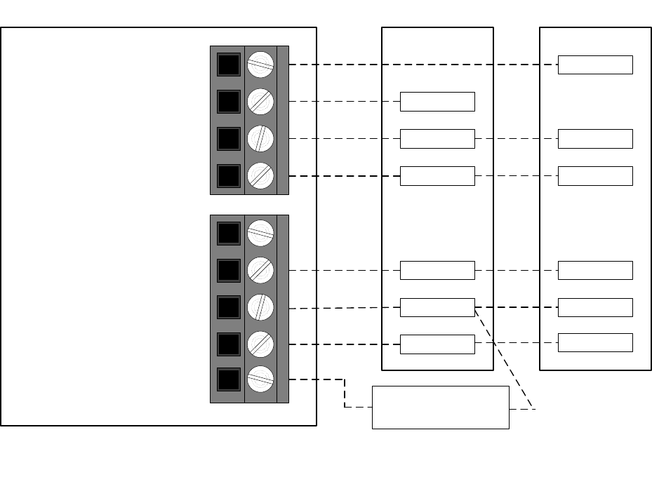
Fig. 20 -- FV/FK Fan Coil with 2--Stage Heat Pump
Fig. 21 -- Typical Single Stage Furnace or Fan Coil with Single Stage Heat Pump
Fig. 22 -- Fan Coil Shown w/Aux. Connection #1 (Heat Pump/Air Conditioner removed for
clarity.)*
Fig. 23 -- FV/FK Fan Coil w/2--Stage Air Conditioner
Fig. 24 -- Typical Fan Coil with Air Conditioner
Fig. 25 -- Fan Coil Shown with Aux. Connection #2 (Heat Pump/Air Conditioner removed
for clarity.)*
Fig. 26 -- FV/FK Fan Coil with 1--Stage Heat Pump
Fig. 27 -- Typical Fan Coil Heating Only
Fig. 28 -- Thermidistat Control w/Dry Contact Control for Fan Run Time*
Fig. 29 -- FV/FK Fan Coil with 1--Stage Air Conditioner
Fig. 30 -- Typical Fan Coil Cooling Only
Fig. 31 -- Variable Speed, Multi--Stage, Stage Modulating and Single-Stage Furnace with 2-
-Stage Heat Pump
Fig. 32 -- Single--Stage Furnace with Heat Pump
(Hybrid Heat)
Fig. 33 -- Variable Speed, Step Modulating, Multi--Stage and Single-Stage Furnace with
Two--Stage Air Conditioner
Fig. 34 -- Single--Stage Furnace with Single--Speed Air Conditioner
Fig. 35 -- Variable Speed, Multi--Stage and Step Modulating Furnace with Single--Stage
Heat Pump
Fig. 36 -- Single--Stage Furnace Heating Only
Fig. 37 -- Variable Speed, Multi--Stage, Step Modulating and Single-Stage Furnace with
Single--Stage Air Conditioner
Fig. 38 -- Single--stage Furnace with Air Conditioner and Split Power
*Fig. 19, Fig 22, Fig. 25, and Fig 28 are all shown in the 2-wire relay installation
instructions.
39
WIRING DIAGRAMS
Y/Y2
G
W1
R
C
Y/Y2
C
Fan Coil Heat Pump
R
O/W2/B
G
Y1/W2
Y/Y2
Rc/V+
Rh
C/Vg
W/W1
HUM*
O O
W1
Fan
24VAC Hot Cooling
24VAC Hot Heating
24VAC Common
Aux Heat (Stage 3)
Humidify
Reversing Valve
W2
Heat/Cool (Stage 2)
Heat/Cool (Stage 1) Y1 Y1
Côr 5, Côr 5C, Côr 7, or Côr 7C Thermostat
Humidifier Solenoid
Valve*
* Indicates connection may not be required/available
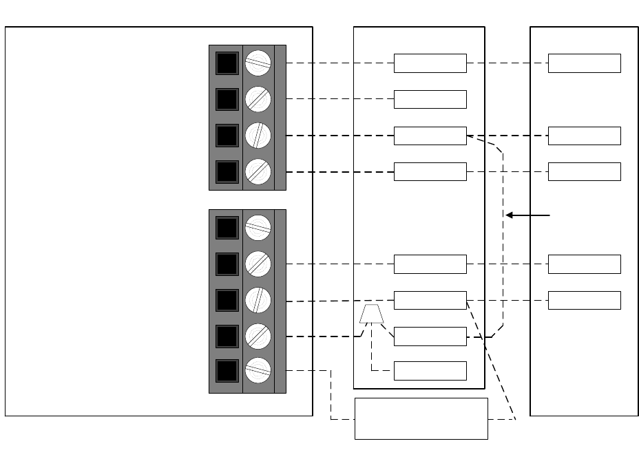
Fig. 20 -- FV/FK Fan Coil with 2--Stage Heat Pump
40
G
W2
R
C
Y
C
Fan CoilCôr 5, Côr 5C, Côr 7, or Côr 7C Thermostat Heat Pump
R
O/W2/B
G
Y1/W2
Y/Y2
Rc/V+
Rh
C/Vg
W/W1
HUM*
O
W2
Fan
N/A
Cool Stage 1
24VAC Hot Cooling
24VAC Common
Heat Stage 1
Humidify
24VAC Hot Heating
E
Humidifier Solenoid
Valve*
* Indicates connection may not be required/available
Reversing Valve
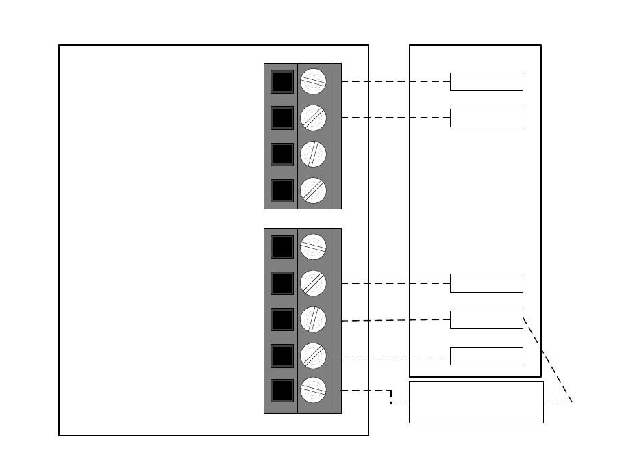
Fig. 21 -- Typical Fan Coil with Heat Pump
41
Y/Y2
G
W/W1
R
C
Y2
C
Fan Coil Air Conditioner
R
O/W2/B
G
Y1/W2
Y/Y2
Rc/V+
Rh
C/Vg
W/W1
HUM*
W2
Fan
Cool Stage 1
Cool Stage 2
24VAC Hot Cooling
24VAC Hot Heating
24VAC Common
Heat Stage 1
Humidify
Heat Stage 2
Y1 Y1
Humidifier Solenoid
Valve*
Côr 5, Côr 5C, Côr 7, or Côr 7C Thermostat
* Indicates connection may not be required/available
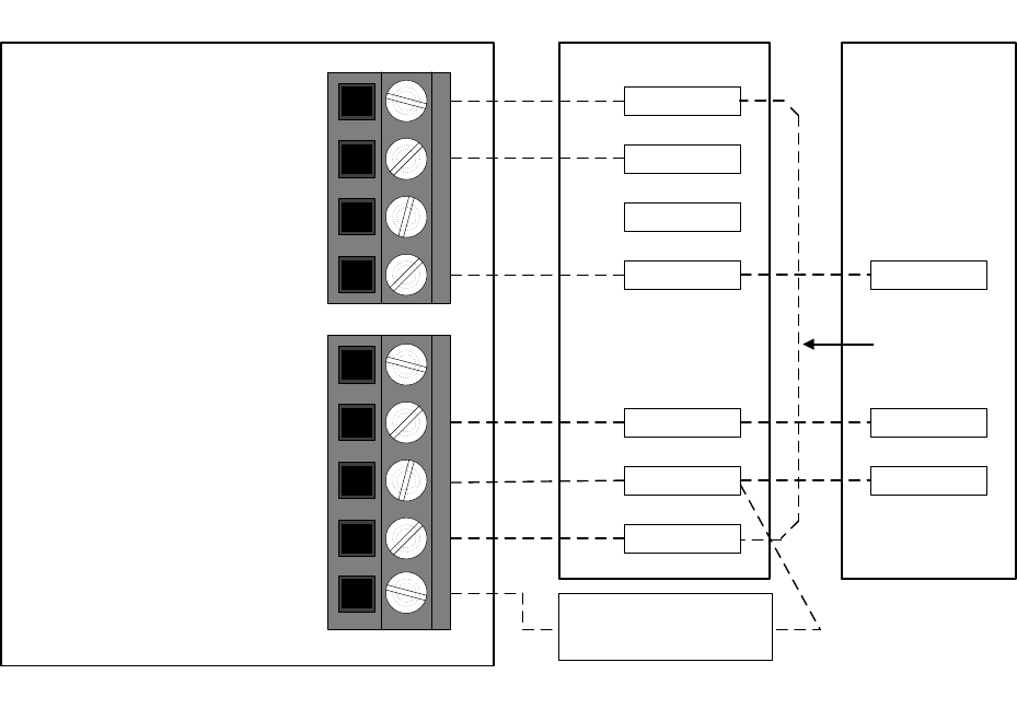
Fig. 23 -- FV/FK Fan Coil w/2--Stage Air Conditioner
42
Y
G
W2
R
C
Y
C
Typical
Fan Coil
Single-Stage
Air Conditioner
R*
O/W2/B
G
Y1/W2
Y/Y2
Rc/V+
Rh
C/Vg
W/W1
HUM*
W3
* Indicates connection may not be required/available
Fan
N/A
Cool Stage 1
24VAC Hot Cooling
24VAC Hot Heating
24VAC Common
Heat Stage 1
Humidify
Heat Stage 2
Humidifier Solenoid
Valve*
E
Côr 5, Côr 5C, Côr 7, or Côr 7C Thermostat
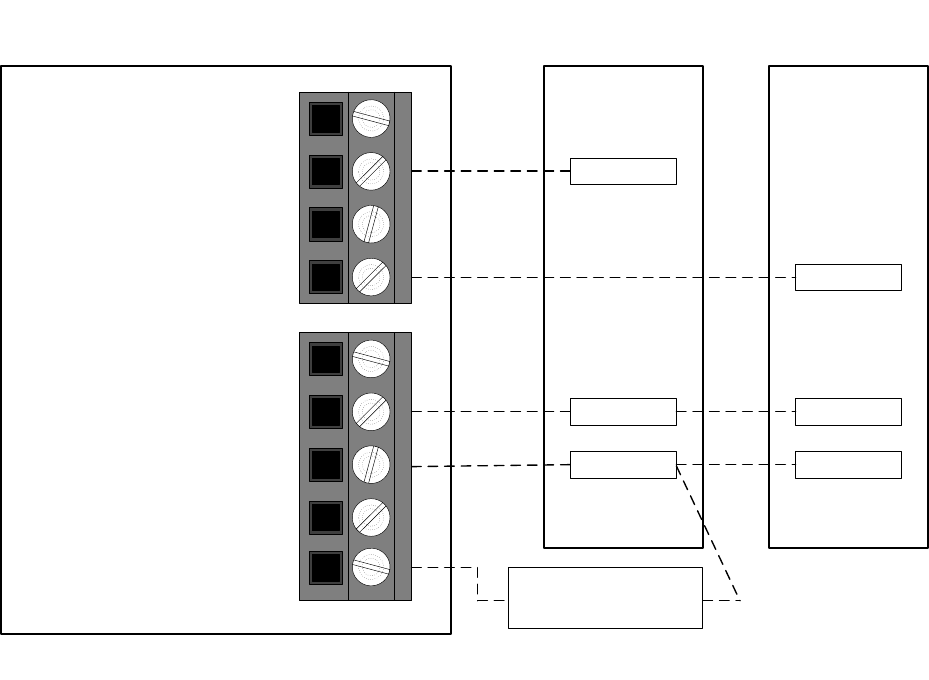
Fig. 24 -- Typical Fan Coil with Air Conditioner
43
Y
G
W1
R
C
Y
C
Fan Coil Heat Pump
R
O/W2/B
G
Y1/W2
Y/Y2
Rc/V+
Rh
C/Vg
W/W1
HUM*
O ORVS Cooling
Fan
Heat Stage 3
Heat/Cool Stage 1
24VAC Hot Cooling
24VAC Hot Heating
24VAC Common
Heat Stage 2
Humidify E
W2W2
Remove J2
Jumper for
heat staging
Côr 5, Côr 5C, Côr 7, or Côr 7C Thermostat
* Indicates connection may not be required/available
Humidifier Solenoid
Valve*
Fig. 26 -- FV/FK Fan Coil with 1--Stage Heat Pump
44
G
W2
R
C
Typical Fan
Coil
O/W2/B
G
Y1/W2
Y/Y2
Rc/V+
Rh
C/Vg
W/W1
HUM*
E
* Indicates connection may not be required/available
Heat Stage 2
Fan
N/A
N/A
24VAC Hot Cooling
24VAC Hot Heating
24VAC Common
Heat Stage 1
Humidify Humidifier Solenoid
Valve*
Côr 5, Côr 5C, Côr 7, or Côr 7C Thermostat
Fig. 27 -- Typical Fan Coil Heating Only
45
Y/Y2
G
W1
R
C
Y
C
Fan Coil Air Conditioner
R
O/W2/B
G
Y1/W2
Y/Y2
Rc/V+
Rh
C/Vg
W/W1
HUM*
W2Heat Stage 2
Fan
N/A
Cool Stage 1
24VAC Hot Cooling
24VAC Hot Heating
24VAC Common
Heat Stage 1
Humidify
Y1
Remove J2
Jumper for
heat staging
Côr 5, Côr 5C, Côr 7, or Côr 7C Thermostat
Humidifier Solenoid
Valve*
* Indicates connection may not be required/available
Fig. 29 -- FV/FK Fan Coil with 1--Stage Air Conditioner
46
G
R
C
Y
C
Typical
Fan Coil
Single-Stage
Air Conditioner
R*
O/W2/B
G
Y1/W2
Y/Y2
Rc/V+
Rh
C/Vg
W/W1
HUM*
* Indicates connection may not be required/available
Fan
NA
Compressor High
24VAC Hot Cooling
24VAC Hot Heating
24VAC Common
Heat Stage 1
Humidify
NA
Humidifier Solenoid
Valve*
Côr 5, Côr 5C, Côr 7, or Côr 7C Thermostat
Fig. 30 -- Typical Fan Coil Cooling Only
47
Y/Y2
G
W/W1
R
C
Y/Y2
C
Furnace Heat Pump
R
O/W2/B
G
Y1/W2
Y/Y2
Rc/V+
Rh
C/Vg
W/W1
HUM*
O
** Some heat pumps may designate W1
W2**
Fan
Heat/Cool (Stage 1)
Heat/Cool (Stage 2)
24VAC Hot Cooling
24VAC Hot Heating
24VAC Common
Aux Heat (Stage 3)
Humidify
Reversing Valve
Y1 Y1
Côr 5, Côr 5C, Côr 7, or Côr 7C Thermostat
Humidifier Solenoid
Valve*
* Indicates connection may not be required/available
Fig. 31 -- Variable Speed, Multi--Stage, Stage Modulating and Single—StageFurnace with
2--Stage Heat Pump
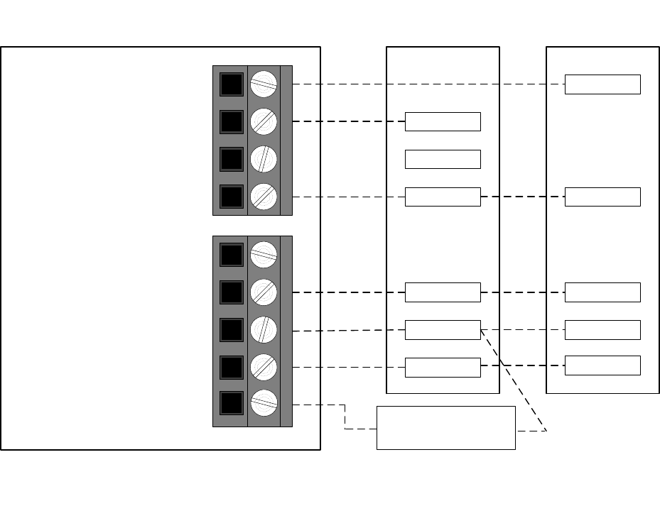
48
Y/Y2
G
W
R
C
Y
C
Furnace
Single Stage
Heat Pump
R
O/W2/B
G
Y1/W2
Y/Y2
Rc/V+
Rh
C/Vg
W/W1
HUM*
O
** Some heat pumps may designate W1
W2**
Fan
N/A
Heat/Cool (Stage 1)
24VAC Hot Cooling
24VAC Hot Heating
24VAC Common
Heat Stage 2 (furnace)
Humidify
Reversing Valve
Y1
Côr 5, Côr 5C, Côr 7, or Côr 7C Thermostat
* Indicates connection may not be required/available
Humidifier Solenoid
Valve*
Fig. 32 -- Single--Stage Furnace with Heat Pump
(Hybrid Heat)
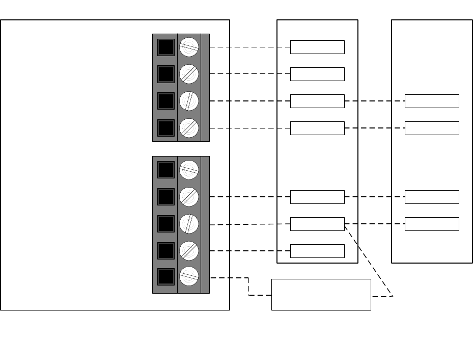
49
Y/Y2
G
W/W1
R
C
Y/Y2
C
Furnace Air Conditioner
R
O/W2/B
G
Y1/W2
Y/Y2
Rc/V+
Rh
C/Vg
W/W1
HUM*
Fan
Cool (Stage 1)
Cool (Stage 2)
24VAC Hot Cooling
24VAC Hot Heating
24VAC Common
Heat Stage 1
Humidify
Heat Stage 2
Y1 Y1
W2
Côr 5, Côr 5C, Côr 7, or Côr 7C Thermostat
Humidifier Solenoid
Valve*
* Indicates connection may not be required/available
Fig. 33 -- Variable Speed, Step Modulating, Multi--Stage and Single—StageFurnace with
Two--Stage Air Conditioner
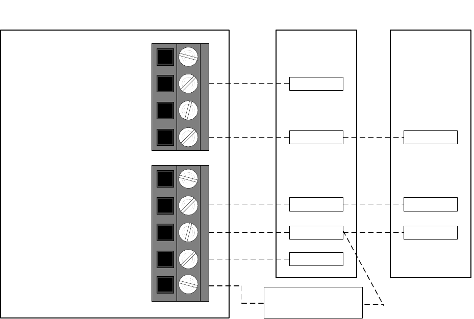
50
Y
G
W
C
Y
C
Furnace
Single-Stage
Air Conditioner
* Indicates connection may not be required/available
O/W2/B
G
Y1/W2
Y/Y2
Rc/V+
Rh
C/Vg
W/W1
HUM*
N/A
Fan
N/A
Cool Stage 1
24VAC Hot Cooling
24VAC Hot Heating
24VAC Common
Heat Stage 1
Humidify
R R*
Côr 5, Côr 5C, Côr 7, or Côr 7C Thermostat
Humidifier Solenoid
Valve*
Fig. 34 -- Single--Stage Furnace with Single--Speed Air Conditioner
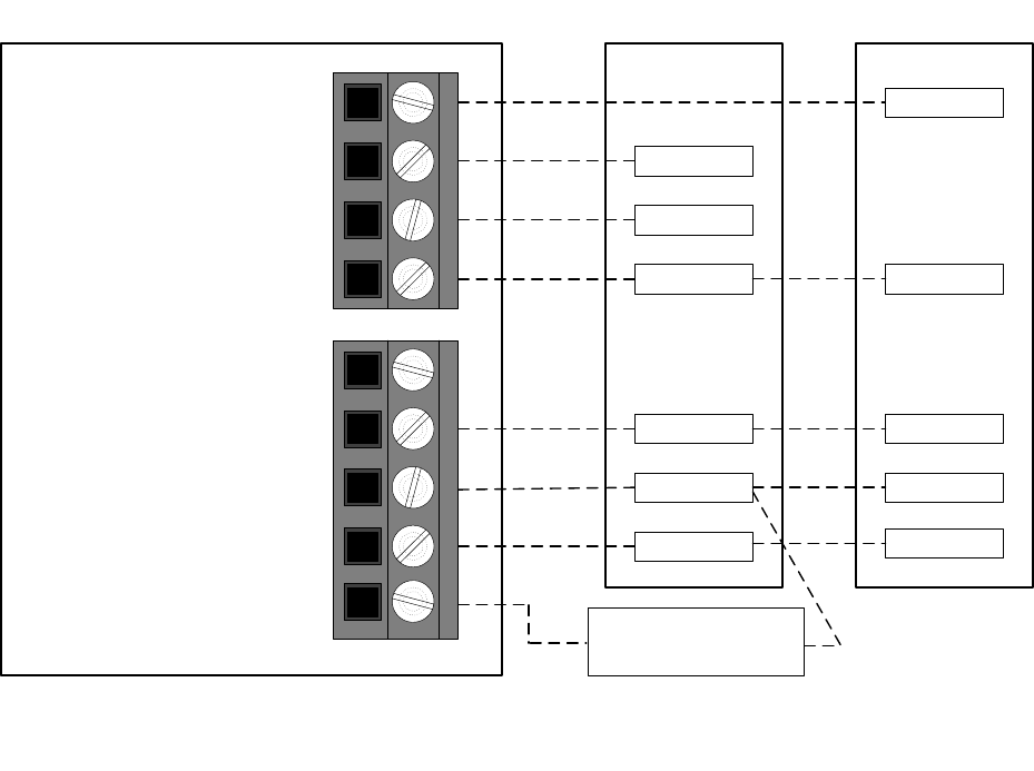
51
Y/Y2
G
W/W1
R
C
Y
C
Furnace Heat Pump
R
O/W2/B
G
Y1/W2
Y/Y2
Rc/V+
Rh
C/Vg
W/W1
HUM*
O
** Some heat pumps may designate W1
W2**
Fan
Heat Stage 3 (furnace)
Heat/Cool (Stage 1)
24VAC Hot Cooling
24VAC Hot Heating
24VAC Common
Heat Stage 2 (furnace)
Humidify
Reversing Valve
W2
Côr 5, Côr 5C, Côr 7, or Côr 7C Thermostat
* Indicates connection may not be required/available
Humidifier Solenoid
Valve*
Fig. 35 -- Variable Speed, Multi--Stage and Modulating Furnace withSingle--Stage Heat
Pump
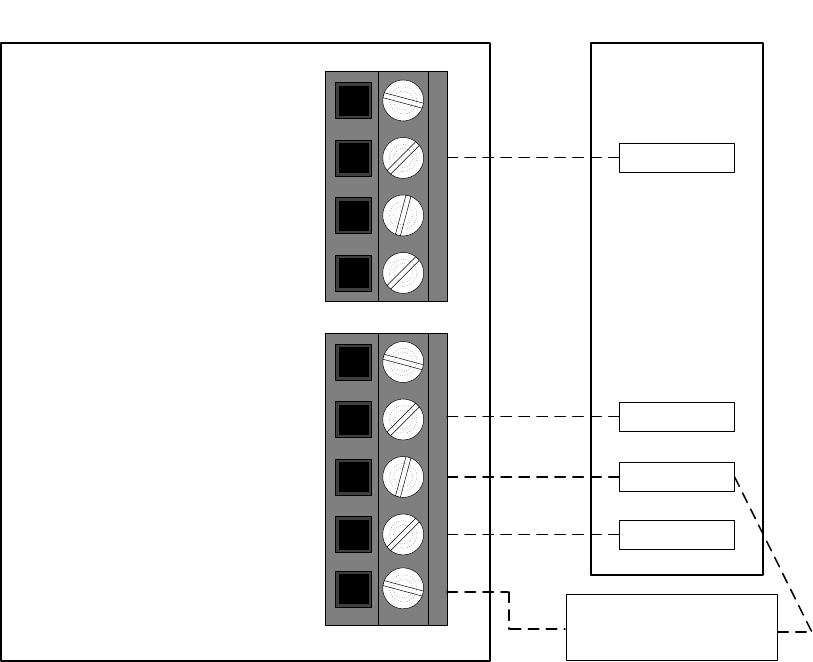
52
G
W
C
Furnace
* Indicates connection may not be required/available
O/W2/B
G
Y1/W2
Y/Y2
Rc/V+
Rh
C/Vg
W/W1
HUM*
N/A
Fan
N/A
N/A
24VAC Hot Cooling
24VAC Hot Heating
24VAC Common
Heat Stage 1
Humidify
R
Côr 5, Côr 5C, Côr 7, or Côr 7C Thermostat
Humidifier Solenoid
Valve*
Fig. 36 -- Single--Stage Furnace Heating Only
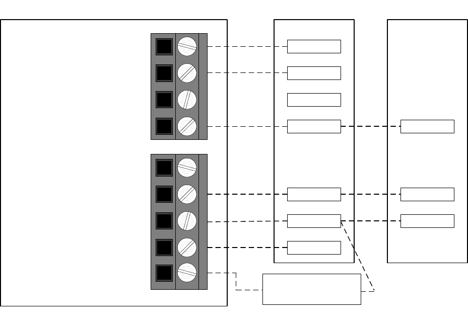
53
Y/Y2
G
W/W1
R
C C
Furnace Air Conditioner
R*
O/W2/B
G
Y1/W2
Y/Y2
Rc/V+
Rh
C/Vg
W/W1
HUM*
* Indicates Connection may not be required/available.
Fan
N/A
Cool Stage 1
24VAC Hot Cooling
24VAC Hot Heating
24VAC Common
Heat Stage 1
Humidify
Heat Stage 2
Y1
Y
W2
Côr 5, Côr 5C, Côr 7, or Côr 7C Thermostat
Humidifier Solenoid
Valve*
Fig. 37 -- Variable Speed, Multi--Stage, Step Modulating and Single--Stage
Furnace with Single--Stage Air Conditioner
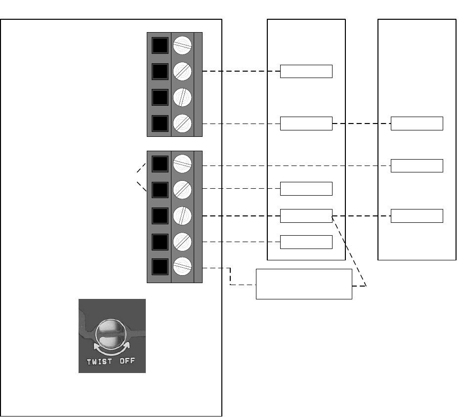
54
Y
G
W
C
Y
C
Furnace Air Conditioner
* Indicates connection may not be required/available
O/W2/B
G
Y1/W2
Y/Y2
Rc/V+
Rh
C/Vg
W/W1
HUM*
N/A
Fan
N/A
Cool Stage 1
24VAC Hot Cooling
24VAC Hot Heating
24VAC Common
Heat Stage 1
Humidify
R
Côr 5, Côr 5C, Côr 7, or Côr 7C Thermostat
Humidifier Solenoid
Valve*
R
Note: Twist off PCB breakout jumper to
separate Rc and Rh.
Fig. 38 -- Single--stage Furnace with Air Conditioner and Split Power
55
NOTES
56
NOTES
FCC:
This device complies with Part 15 of the FCC Rules. Operation is subject to the following two
conditions: (1) This device may not cause harmful interference, and (2) This device must accept
any interference received, including interference that may cause undesired operation.
Changes or modifications not expressly approved by the party responsible for compliance could
void the user’s authority to operate the equipment.
This equipment has been tested and found to comply with the limits for a Class B digital device,
pursuant to part 15 of the FCC Rules. These limits are designed to provide reasonable protection
against harmful interference in a residential installation. This equipment generates, uses and can
radiate radio frequency energy and, if not installed and used in accordance with the instructions,
may cause harmful interference to radio communications. However, there is no guarantee that
interference will not occur in a particular installation. If this equipment does cause harmful
interference to radio or television reception, which can be determined by turning the equipment
off and on, the user is encouraged to try to correct the interference by one or more of the
following measures:
—Reorient or relocate the receiving antenna.
—Increase the separation between the equipment and receiver.
—Connect the equipment into an outlet on a circuit different from that to which the receiver is
connected.
—Consult the dealer or an experienced radio/TV technician for help.
To comply with FCC/IC RF exposure limits for general population / uncontrolled exposure, the
antenna(s) used for this transmitter must be installed to provide a separation distance of at least
20 cm from all persons and must not be co-located or operating in conjunction with any other
antenna or transmitter.
Pour se conformer aux limites d'exposition RF FCC et IC pour la population générale /
l'exposition incontrôlée, l'antenne utilisée pour cet émetteur doit être installée pour assurer une
distance de séparation d'au moins 20 cm de toutes les personnes et fonctionnant conjointement
avec toute autre antenne ou émetteur.
This Device complies with Industry Canada License-exempt RSS standard(s). Operation is
subject to the following two conditions: 1) this device may not cause interference, and 2) this
device must accept any interference, including interference that may cause undesired operation
of the device.
Cet appareil est conforme avec Industrie Canada, exempts de licence standard RSS (s). Son
fonctionnement est soumis aux deux conditions suivantes: 1) ce dispositif ne peut pas causer
d'interférences, et 2) ce dispositif doit accepter toute interférence, y compris les interférences qui
peuvent causer un mauvais fonctionnement de l'appareil.

57
997---060360---10---R
Copyright 2013 Carrier Corporation 7310 W Morris St. Indianapolis, IN 46231
TP---PRH---10SI Replaces: TP--- PRH--- 09SI
Edition Date: 07/13
Manufacturer reserves the right to change, at any time, specifications and designs without notice
and without obligations.
58