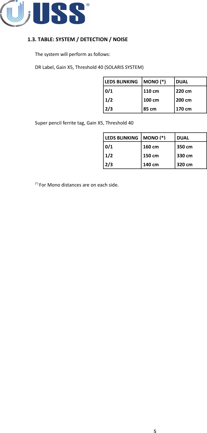
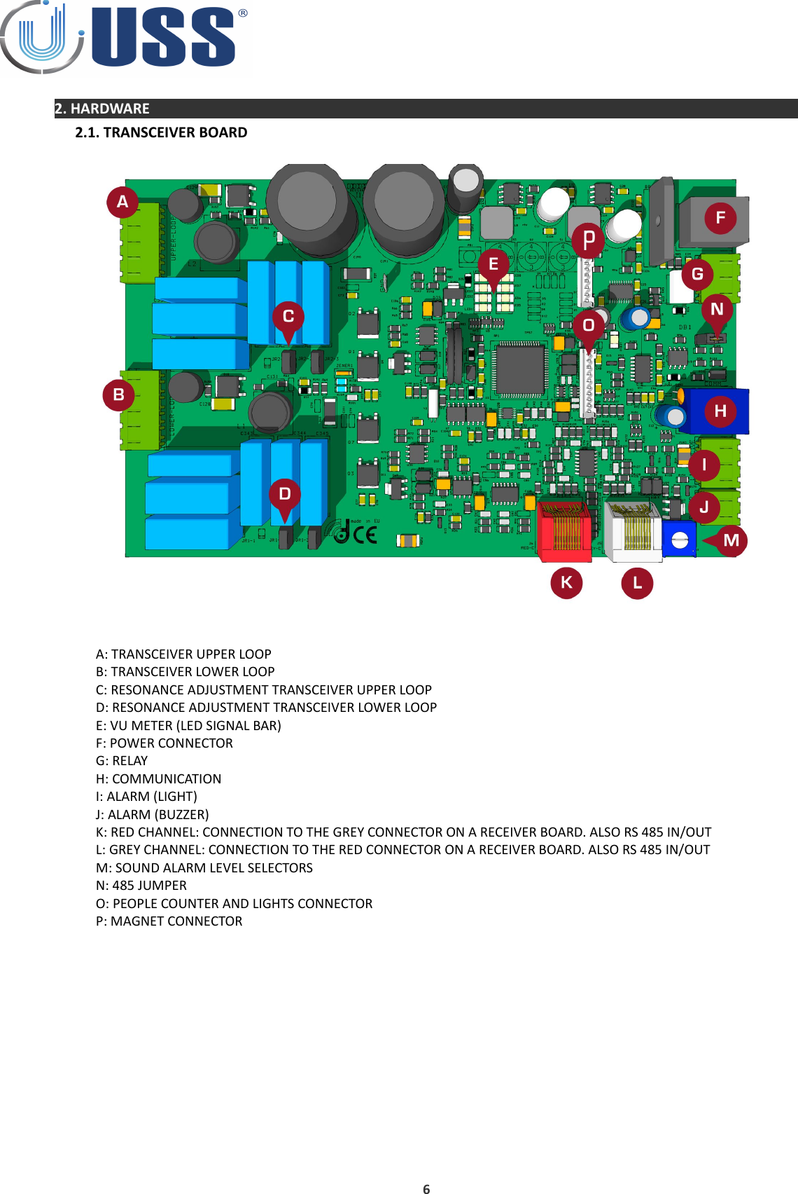
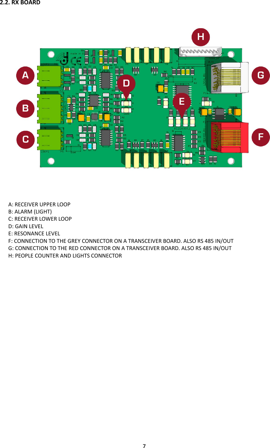
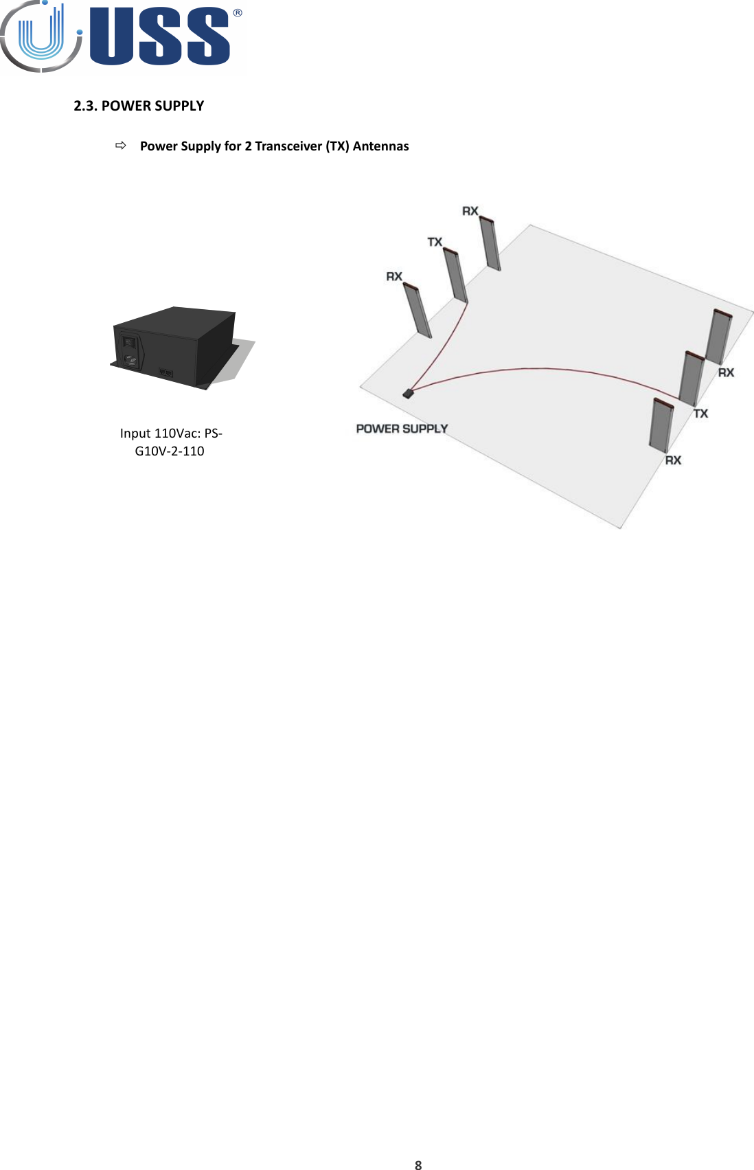
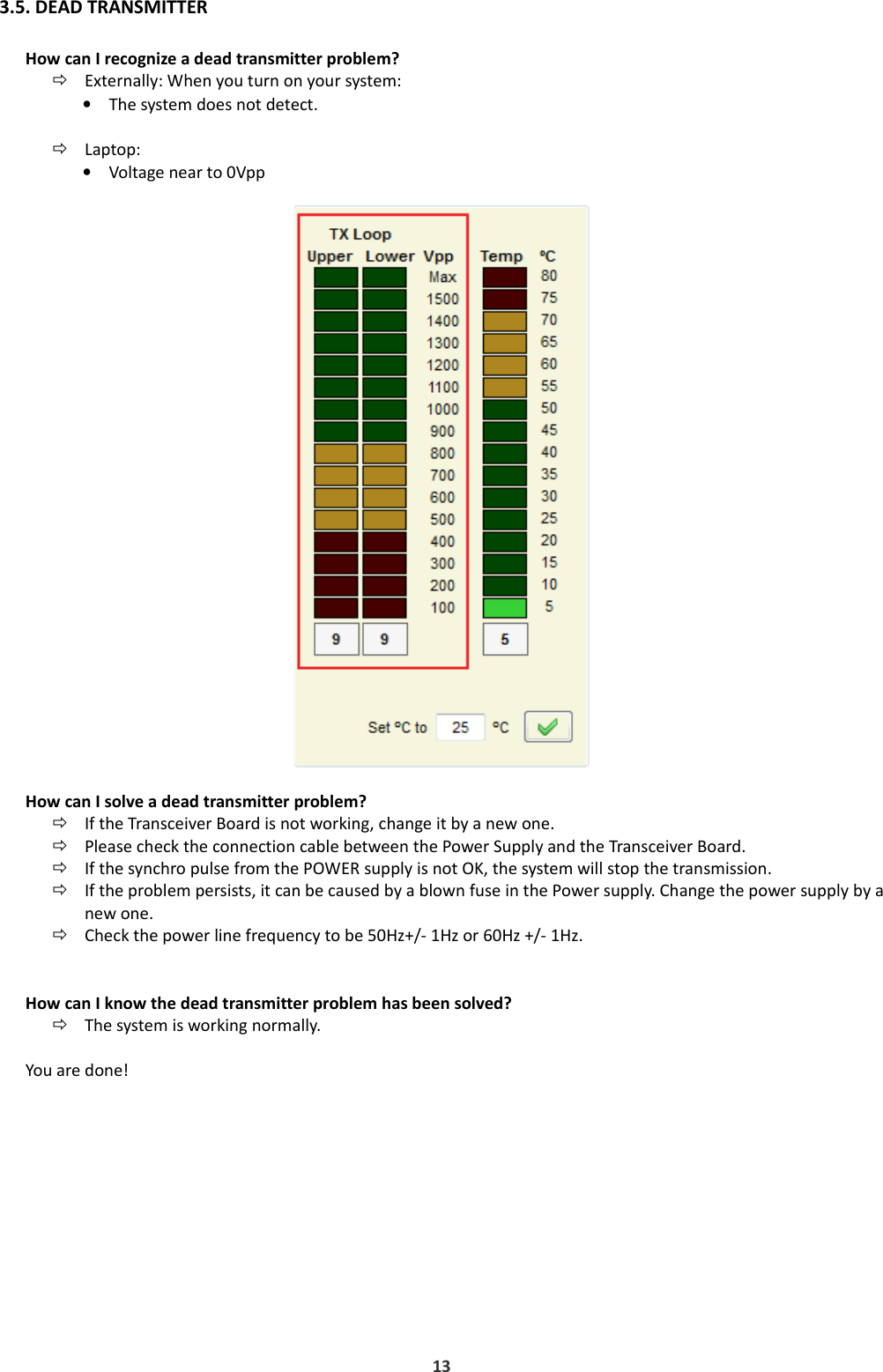
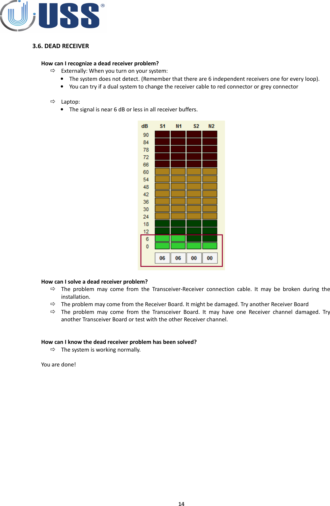
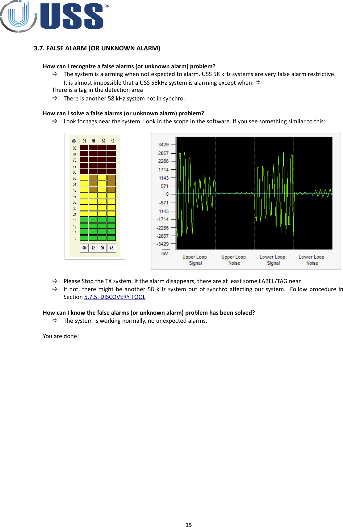
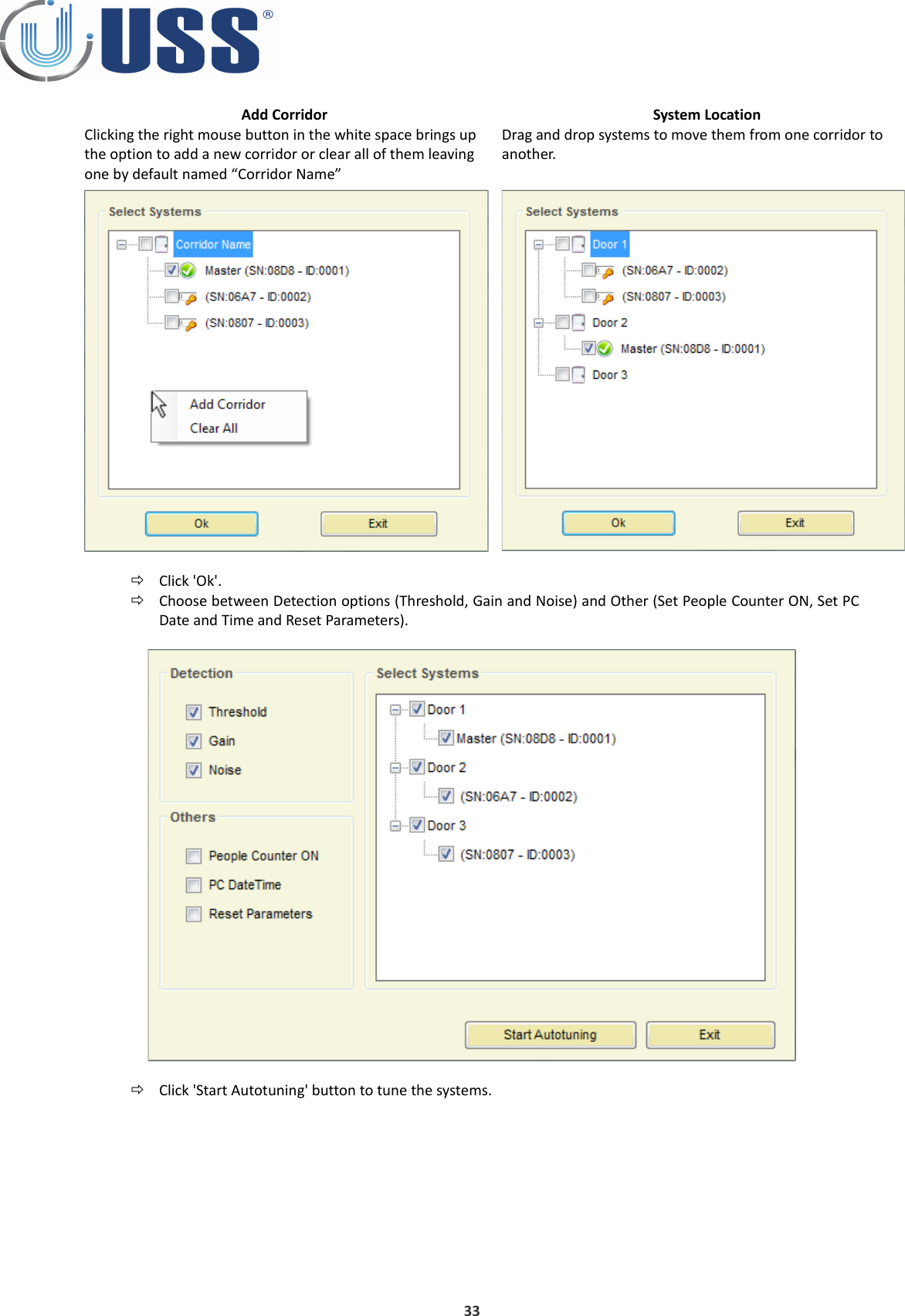
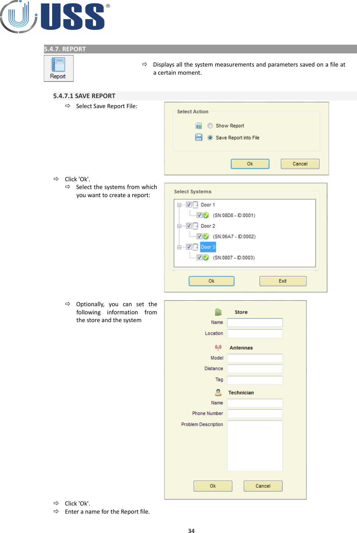
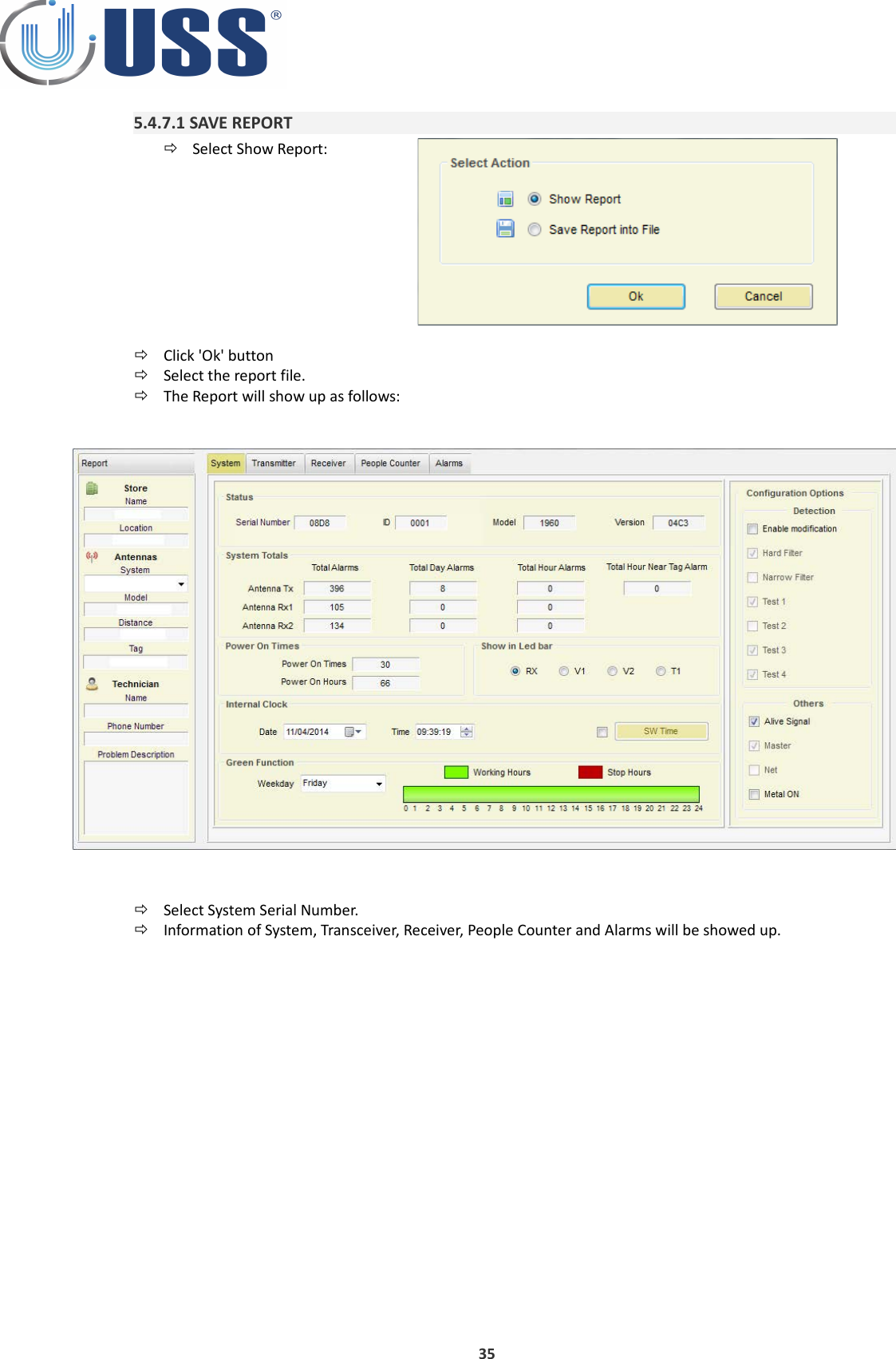
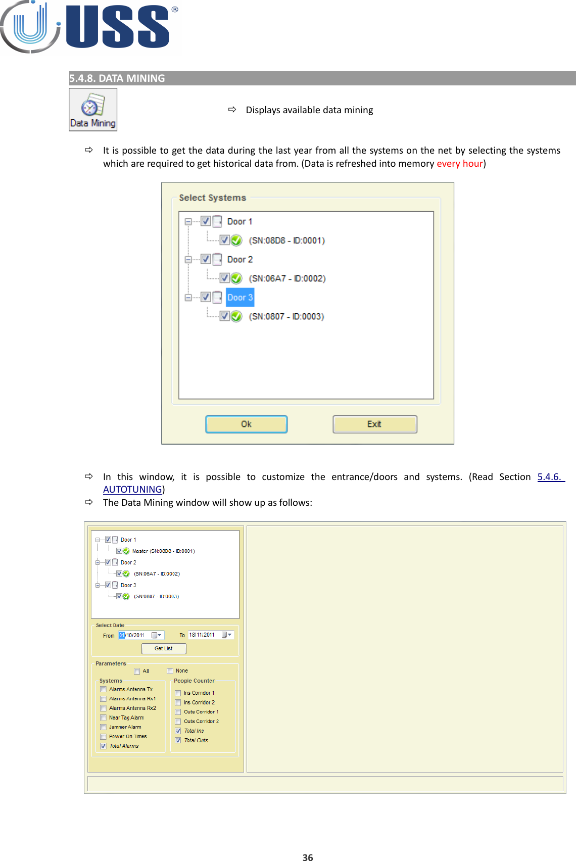
Universal Surveillance Systems USS-AMBLADE 58 kHz Pedestal User Manual Tuning G10V Manual

Universal Surveillance Systems, LLC 58 kHz Pedestal Tuning G10V Manual

User Manual

    BLADE MANUALSoftware Version 39.6 Document Version 1.14 Date 25 January 2015
1. G10V SYSTEM OVERVIEW.....................................................................................................................................41.1. DESCRIPTION................................................................................................................................................41.2. SPECIFICATIONS............................................................................................................................................41.2.1. TRANSCEIVER.......................................................................................................................................41.2.2. RECEIVER..............................................................................................................................................41.2.3. POWER SUPPLY....................................................................................................................................41.3. TABLE: SYSTEM / DETECTION / NOISE............................................................................................................52. HARDWARE..........................................................................................................................................................62.1. TRANSCEIVER BOARD...................................................................................................................................62.2. RX BOARD....................................................................................................................................................72.3. POWER SUPPLY.............................................................................................................................................83. QUICK TUNING.....................................................................................................................................................93.1. QUICK INSTALLATION....................................................................................................................................93.1.1. PREVIOUS............................................................................................................................................93.1.2. SYSTEM INSTALLATION.........................................................................................................................93.2. TROUBLESHOOTING.....................................................................................................................................93.2.1. NO DETECTION.....................................................................................................................................93.2.2. TOO MUCH DETECTION........................................................................................................................93.2.3. FALSE ALARM.......................................................................................................................................93.2.4. MAKES OTHER SYSTEMS FALSE ALARM.................................................................................................93.3. SYNCHRONIZATION PROBLEM.....................................................................................................................103.4. NOISE PROBLEM.........................................................................................................................................113.5. DEAD TRANSMITTER...................................................................................................................................133.6. DEAD RECEIVER..........................................................................................................................................143.7. FALSE ALARM (OR UNKNOWN ALARM).......................................................................................................154. CONFIGURATION................................................................................................................................................164.1. CONNECTION METHOD...............................................................................................................................164.1.1. ANTENNA CABLES AND CONNECTION.................................................................................................16MATERIAL....................................................................................................................................................16PROCESS......................................................................................................................................................164.1.2. POWER SUPPLY CABLE AND CONNECTION...........................................................................................17MATERIAL....................................................................................................................................................17PROCESS......................................................................................................................................................174.2. CONFIGURATION EXAMPLES.......................................................................................................................184.2.1. TRANSCEIVER BOARDS.......................................................................................................................184.2.2. RECEIVER BOARDS..............................................................................................................................184.2.3. DUAL SYSTEM CONFIGURATION (RX-TX)..............................................................................................194.2.4. SPLIT SYSTEM CONFIGURATION (RX-TX-RX).........................................................................................205.SOFTWARE...........................................................................................................................................................215.1. INSTALLATION PROCEDURE..........................................................................................................................215.2. CONNECT.....................................................................................................................................................225.2.1. RS232 PORT.........................................................................................................................................225.2.2. ANALOG MODEM................................................................................................................................235.2.3. GSM MODEM......................................................................................................................................245.2.4. INTERNET MODULE..............................................................................................................................255.2.5. HOW TO KNOW THE COM PORT..........................................................................................................265.3. ACCESS.........................................................................................................................................................275.4. MAIN MENU................................................................................................................................................295.4.1. SETTINGS.............................................................................................................................................295.4.2. CONNECT /CONNECTED.......................................................................................................................315.4.3. DISCONNECT........................................................................................................................................315.4.4. PARAMETERS.......................................................................................................................................315.4.5. COMMANDS TRANSMISSION...............................................................................................................315.4.6. AUTOTUNING......................................................................................................................................325.4.7. REPORT................................................................................................................................................342
5.4.7.1 SAVE REPORT....................................................................................................................................345.4.7.1 SAVE REPORT....................................................................................................................................355.4.8. DATA MINING.....................................................................................................................................36TABLE DATA..................................................................................................................................................37CHART DATA.................................................................................................................................................38SYSTEMS DATA.............................................................................................................................................395.4.9. MANUAL.............................................................................................................................................405.4.10. LANGUAGES......................................................................................................................................405.4.11. UPDATE.............................................................................................................................................415.5. SYSTEMS......................................................................................................................................................425.6. SYSTEM TAB.................................................................................................................................................435.6.1. STATUS................................................................................................................................................435.6.2. SYSTEM TOTALS...................................................................................................................................435.6.3. POWER TIMES......................................................................................................................................445.6.4. LEDS.....................................................................................................................................................44 5.6.5. CLOCK..................................................................................................................................................44SUMMER / WINTER TIME (DAYLIGHT SAVING TIME)......................................................................................445.6.6. SAVE ENERGY.......................................................................................................................................45STOP HOURS..................................................................................................................................................45STOP DAYS.....................................................................................................................................................45GREEN FUNCTION..........................................................................................................................................455.6.7. CONFIGURATION OPTIONS..................................................................................................................465.7. TRANSMITTER TAB.......................................................................................................................................475.7.1. START / STOP TX..................................................................................................................................475.7.2. TX LOOPS.............................................................................................................................................475.7.3. MULTIMONO.......................................................................................................................................475.7.4. DISCOVERY TOOL.................................................................................................................................47FIELD SITUATIONS.........................................................................................................................................515.7.5. TRANSCEIVER STATUS.........................................................................................................................535.8. RECEIVER TAB..............................................................................................................................................545.8.1. GAIN....................................................................................................................................................545.8.2. THRESHOLD.........................................................................................................................................545.8.3. START/STOP RECEIVER LOOPS..............................................................................................................555.8.4. ANTI NOISE ALGORITHMS....................................................................................................................555.8.5. SIGNAL AND NOISE ..............................................................................................................................565.9. PEOPLE COUNTER TAB..................................................................................................................................575.9.1. IR-RX MODULES (ACC-PCA-G10V PEOPLE COUNTER A).........................................................................575.9.2. IR-TX MODULES (ACC-PCB-G10V PEOPLE COUNTER B).........................................................................585.9.2.1. IR POWER TRANSMISSION................................................................................................................585.9.3. PEOPLE COUNTER INSTALLATION.........................................................................................................59PING PONG TRANSMISSION...........................................................................................................................60AUTO CONFIGURATION.................................................................................................................................605.10. ALARMS TAB..............................................................................................................................................625.10.1. SOUND OPTIONS................................................................................................................................625.10.2. PAGER OPTIONS.................................................................................................................................625.10.3. ALARM TYPES.....................................................................................................................................635.11. CUSTOM SETUP..........................................................................................................................................645.11.1. CUSTOMIZING INSTALLATION PROCESS..............................................................................................645.11.2. CUSTOMIZING SOFTWARE ICON.........................................................................................................646. SAFETY AND DECLARATIONS................................................................................................................................656.1. SAFETY GUIDELINES.....................................................................................................................................656.2. FCC DISCLAIMER...........................................................................................................................................653
1. G10V SYSTEM OVERVIEW1.1. DESCRIPTIONUSS G10V AM systems can detect any 58 kHz resonant circuit or any acousto magnetic tag passing through the detection area.The system includes Digital Processing System (DPS) in order to achieve great detection range, filtering noise and avoiding possible false alarms.The tuning is done easily via powerful software. The system can be accessed via laptop and optionally via Internet, Analog MODEM, GSM MODEM, etc.…USS 58 kHz systems can have several configurations: 1 Transceiver pedestalMono-antenna:Dual System:Split System: 2 pedestals (TX-RX)  3 pedestals (RX-TX-RX)1.2. SPECIFICATIONS1.2.1. TRANSCEIVERELECTRICALOperating Frequency58 kHzTransmit Burst Duration1.5 msTransmit Burst Repetition Rates 50Hz 75 or 50 pulses/second (TX burst 1.5ms)       60Hz 90 or 60 pulses/second (TX burst 1.5ms)Transmit coil Resistance1.5 Ohm1.2.2. RECEIVERELECTRICALOperating Frequency58 kHzInputs2Receive coil Resistance1.5 Ohm1.2.3. POWER SUPPLYPS-G10V-2-110ELECTRICAL  Input 110VacOutput2 Outputs (12V – 0 – 12V) Fuse2A 250V Slow ENVIROMENTALR. Humidity0 to 85% non condensingOperating Temperature0º to 50º CNoise level30dBm4
1.3. TABLE: SYSTEM / DETECTION / NOISEThe system will perform as follows:DR Label, Gain X5, Threshold 40 (SOLARIS SYSTEM)LEDS BLINKINGMONO (*)DUAL0/1110 cm220 cm1/2100 cm200 cm2/385 cm170 cmSuper pencil ferrite tag, Gain X5, Threshold 40LEDS BLINKINGMONO (*)DUAL0/1160 cm350 cm1/2150 cm330 cm2/3140 cm320 cm(*) For Mono distances are on each side.5
2. HARDWARE2.1. TRANSCEIVER BOARDA: TRANSCEIVER UPPER LOOPB: TRANSCEIVER LOWER LOOPC: RESONANCE ADJUSTMENT TRANSCEIVER UPPER LOOPD: RESONANCE ADJUSTMENT TRANSCEIVER LOWER LOOPE: VU METER (LED SIGNAL BAR)F: POWER CONNECTORG: RELAY H: COMMUNICATIONI: ALARM (LIGHT)J: ALARM (BUZZER)K: RED CHANNEL: CONNECTION TO THE GREY CONNECTOR ON A RECEIVER BOARD. ALSO RS 485 IN/OUTL: GREY CHANNEL: CONNECTION TO THE RED CONNECTOR ON A RECEIVER BOARD. ALSO RS 485 IN/OUTM: SOUND ALARM LEVEL SELECTORSN: 485 JUMPERO: PEOPLE COUNTER AND LIGHTS CONNECTORP: MAGNET CONNECTOR6
2.2. RX BOARDA: RECEIVER UPPER LOOPB: ALARM (LIGHT)C: RECEIVER LOWER LOOPD: GAIN LEVELE: RESONANCE LEVELF: CONNECTION TO THE GREY CONNECTOR ON A TRANSCEIVER BOARD. ALSO RS 485 IN/OUTG: CONNECTION TO THE RED CONNECTOR ON A TRANSCEIVER BOARD. ALSO RS 485 IN/OUTH: PEOPLE COUNTER AND LIGHTS CONNECTOR7
2.3. POWER SUPPLYPower Supply for 2 Transceiver (TX) Antennas8 Input 110Vac: PS-G10V-2-110
3. QUICK TUNING3.1. QUICK INSTALLATION3.1.1. PREVIOUS Always connect the system to clean power lines (No other electrical devices connected)  In  order  to  avoid  damaging  the  electronics,  do  not  place  any  TURNED  OFF  antenna  near  a  TURNED  ON Transceiver antenna. Please keep the minimum distance, not less than 50cm Do not fix the system to the floor before testing its performance FIRST! Do not place Receiver and Power line (220Vac/110Vac) cables along the same route.  Please Read this manual BEFORE installing systems!3.1.2. SYSTEM INSTALLATIONCheck cabling / connection needs according to the kind of installation. (See Section 4. CONFIGURATION). Check all the material is ready.Place the system in the installation area.  (DO NOT fix the system to the floor).Turn the system ON, and connect to the system (Follow Section 5. SOFTWARE)Check Electrical Noise, Synchro, TX Status, etc.… check everything is normal.Stabilize external electrical noise to the minimum.Check Section 1.3. TABLE: SYSTEM / DETECTION / NOISE to define the maximum detection distance.If any modifications, save parameters.Disconnect your laptop and observe the system during some time making several detection tests (buzzer can be disabled to not cause disturbance). If OK, fix the system to the floor , if not OK, see Section 3.2. TROUBLESHOOTINGYou are done!3.2. TROUBLESHOOTING3.2.1. NO DETECTIONTry with other tagRise Gain (Up to 2-3 LEDS)Lower ThresholdSee Section 3.4. NOISE PROBLEMSee Section 3.3. SYNCHRONIZATION PROBLEMSee Section 3.5. DEAD TRANSMITTERSee Section 3.6. DEAD RECEIVER3.2.2. TOO MUCH DETECTIONLower GainRise Threshold3.2.3. FALSE ALARMLook for TAGS near the antennasSee Section 3.7. FALSE ALARM (OR UNKNOWN ALARM)3.2.4. MAKES OTHER SYSTEMS FALSE ALARMSee Section 3.3. SYNCHRONIZATION PROBLEM9
3.3. SYNCHRONIZATION PROBLEMHow can I recognize a synchro problem?Externally: When you turn on your system:•It makes other 58 kHz systems near alarm•Your system is showing a high amount of noise in the LED bar (See Section 2. HARDWARE).•There is no detection or it is very poor.Laptop: •Check Section 5.7.5. DISCOVERY TOOLHow can I know the synchro problem has been solved?Externally all systems around will be working fine as well as yours.Laptop: The situation in the discovery mode will be similar to this:You are done!10
3.4. NOISE PROBLEMHow can I recognize a noise problem?Externally: When you turn on your system:•The system shows a high amount of noise in the LED bar.•The detection might be poor.Laptop: •In the scope you will see high amount of noise, in the 4 buffers.How can I solve a noise problem? Try to locate the source of noise:•Turn off all  electrical equipment in the  area. If the noise disappears, start turning all the electricalequipment ONE BY ONE till you get noise again. •Other way to locate the source of noise is moving the Receiver antenna while at the same time you arelooking to the LED bar or the software. See how the orientation of the Receiver antenna affects the amount of noise and you will finally find the source.Then you have to neutralize the source of noise. (It   might be related with bad synchro, please check procedure in Section 5.7.5. DISCOVERY TOOL) Other techniques are:•Swap Transceiver antenna by Receiver antenna position.•Ground the noisy device correctly or try to put it as far as possible from the Receiver antenna.•Use advanced noise techniques 'New Noise fighting algorithms'11
New Noise fighting algorithmsDepending on the level of electrical noise, it is recommended to select different positions in the noise selector. Each antenna is independent.Transceiver antenna•There are 2  active  modes in noisefighting for Transceiver antenna. •Position   0   turns   off   noise   fightingalgorithms in Transceiver antenna.•Back Ground suppressionReceiver antennas•There are 2 active modes in noisefighting for Receiver antennas. •Position   0   turns   off   noise   fightingalgorithms in Receiver antenna.•Back Ground suppressionHow can I know the noise problem has been solved?Detection will improve. The signs of noise in the LED bar and in the scope will disappear.You are done!12
3.5. DEAD TRANSMITTERHow can I recognize a dead transmitter problem?Externally: When you turn on your system:•The system does not detect.Laptop: •Voltage near to 0VppHow can I solve a dead transmitter problem? If the Transceiver Board is not working, change it by a new one. Please check the connection cable between the Power Supply and the Transceiver Board.If the synchro pulse from the POWER supply is not OK, the system will stop the transmission.If the problem persists, it can be caused by a blown fuse in the Power supply. Change the power supply by a new one. Check the power line frequency to be 50Hz+/- 1Hz or 60Hz +/- 1Hz.How can I know the dead transmitter problem has been solved?The system is working normally.You are done!13
3.6. DEAD RECEIVERHow can I recognize a dead receiver problem?Externally: When you turn on your system:•The system does not detect. (Remember that there are 6 independent receivers one for every loop).•You can try if a dual system to change the receiver cable to red connector or grey connectorLaptop: •The signal is near 6 dB or less in all receiver buffers.How can I solve a dead receiver problem? The problem may  come from the Transceiver-Receiver connection cable. It  may be   broken  during  the installation. The problem may come from the Receiver Board. It might be damaged. Try another Receiver BoardThe problem may come  from  the Transceiver Board. It   may   have one  Receiver   channel damaged. Try another Transceiver Board or test with the other Receiver channel.How can I know the dead receiver problem has been solved?The system is working normally.You are done!14
3.7. FALSE ALARM (OR UNKNOWN ALARM)How can I recognize a false alarms (or unknown alarm) problem? The system is alarming when not expected to alarm. USS 58 kHz systems are very false alarm restrictive. It is almost impossible that a USS 58kHz system is alarming except when:  There is a tag in the detection area There is another 58 kHz system not in synchro.How can I solve a false alarms (or unknown alarm) problem?Look for tags near the system. Look in the scope in the software. If you see something similar to this:Please Stop the TX system. If the alarm disappears, there are at least some LABEL/TAG near.If not, there might be another 58 kHz system out of synchro affecting our system.   Follow procedure in Section 5.7.5. DISCOVERY TOOLHow can I know the false alarms (or unknown alarm) problem has been solved?The system is working normally, no unexpected alarms.You are done!15
4. CONFIGURATION4.1. CONNECTION METHODUSS 58 kHz systems have been designed to fit into every installation needs. They can be configured in multiple ways.Connection between Transceivers or between Transceivers and Receivers is done through 10 ways telephonic cable which allows easy adaptation to the installation place needs. 4.1.1. ANTENNA CABLES AND CONNECTIONEach Transceiver antenna can be connected to 2 independent Receiver antennas by a 10 ways flat cable with NOT polarized connectors. Please follow the instructions carefully in order to manufacture the cable correctly. MATERIAL1 x CAB-FL-10-I 2 x CON-10-TEL-NOPOL 1 x ACC-CONTOOL-10PROCESS1. Cut the cable at the necessary length.2. Use the Crimp tool to strip the ends of  the cable.3. Do a cross connection: cables must have the same colour in the same side (means white on left in one edge, in the other edge, left must be also white).Place the cable correctly (same colour order).4. Insert one connector.  NOT POLARIZED for Receiver Boards5.   Insert   second   connector   in   the   same orientation as the first one.6. Crimp the cableConnect the cable between Antennas following Section 4.2. CONFIGURATION EXAMPLESTest the cable with a system to check that it is working correctly.You are done!16
4.1.2. POWER SUPPLY CABLE AND CONNECTIONEach Transceiver antenna must be supplied by a 10 ways flat cable with  Polarized connector. The maximum length for this cable is 15 meter.MATERIAL1 x CAB-FL-10-B 2 x CON-10-TEL-POL 1 x ACC-CONTOOL-10-POLPROCESSFollow the same process as in Section 4.1.1. ANTENNA CABLES AND CONNECTION17
4.2. CONFIGURATION EXAMPLES4.2.1. TRANSCEIVER BOARDSThe connectors from Transceiver Boards which connect to other antennas are red connector (K in the drawing) and  grey  connector  (L  in  the  drawing).  Apart  from  the  RX  signal,  they  also  take  communication  between Transceiver and the 2 local Receiver Boards and communication with further Transceiver Boards in the net, if any. 4.2.2. RECEIVER BOARDSThe connectors in the  Receiver Board are  red   connector  (F  in the  drawing)  and grey connector (G in   the drawing). 18
4.2.3. DUAL SYSTEM CONFIGURATION (RX-TX)Always connect a CAB-FL-10-I cable with CON-10-TEL-NOPOL (NOT POLARIZED) from RED connector of one board to the GREY connector of another board.For Power Supply Connection, always use a CAB-FL-10-B cable with CON-10-TEL-POL (POLARIZED)19
4.2.4. SPLIT SYSTEM CONFIGURATION (RX-TX-RX)Always connect a CAB-FL-10-I cable with CON-10-TEL-NOPOL (NOT POLARIZED) from RED connector of one board to the GREY connector of another board.For Power Supply Connection, always use a CAB-FL-10-B cable with CON-10-TEL-POL (POLARIZED)20
5. SOFTWAREThe interface of Tuning Software for EAS systems has been designed to allow an easy understanding of all features. Icons are highly intuitive permitting a quick assimilation of concepts.5.1. INSTALLATION PROCEDUREBefore installation verify that you have Windows98se or higher.Close all the executing programs.Run the installerSelect the folder to install the software and click 'Install' buttonRun the software:Always connect to the Master to get access to any of the systems (You gain access to all the slaves through the master).21
5.2. CONNECT5.2.1. RS232 PORTUse an USB to Rs232 adaptor if the computer does not have a RS232 port.Connect the communication cable provided to the USB adaptor or directly to the system if the computer has RS232 port.Run   the   software   and   press 'SETTINGS'1. Select Communication2. Select Serial Port.3. Select Serial Port Comm.4. Press OkPress 'Connect'Software   will   search   for   all   the systems connected and load them into the System window22
5.2.2. ANALOG MODEMParts needed: Analog Modem MDM58   Connect the communication cable provided from the analog MODEM to the system.Connect the analog line to the analog MODEM.Test the MODEM sequenceRun   the   software   and   press 'SETTINGS'1. Select Communication.2. Select Modem3. Select Serial Port Comm.4. Enter Phone Number5. Press OkPress 'Connect'Software   will   search   for   all   the systems connected and load them into the System window23
5.2.3. GSM MODEMParts needed: GSM MODEM.Input the SIM CARD into the GSM MODEM.•To enter or  change  PIN  number, access the system using Serial Port connection (See Section  5.2.1.RS232 PORT)•Select   Command   Transmission   (See  Section  5.4.5.   COMMANDS  TRANSMISSION)   and  input   !PNxxxx(xxxx=PIN number)•Save parameters (See Section 5.4.4. PARAMETERS)•Disconnect (See Section 5.4.3. DISCONNECT)Connect the communication cable from the GSM MODEM to the systemAt power on, the system will detect that it has a PIN number and will activate the GSM MODEM. Then it will be on hold waiting for the communication to come through.Follow the same process than Section 5.2.2. ANALOG MODEM24
5.2.4. INTERNET MODULEParts needed: Internet Module ACC-TCP/IPConnect the cable provided to the INTERNET MODULE and to the system.Connect the ETHERNET/ADSL cable line to the INTERNET MODULE.Run   the   software   and   press 'SETTINGS'1. Select Communication.2. Select TCP-IP.3. Enter IP address  and Port4. Select Client or Server operation. •For more information see TCP-IP Modules Manual.•It is possible to save, load or delete the IP/PORT information5. Press OkPress 'Connect'Software   will   search   for   all   the systems connected and load them into the System window25
5.2.5. HOW TO KNOW THE COM PORTIf you are using a USB to RS232 adapter, check which virtual port is assigned by the adapter. To do this, follow the steps: •1. Click on Start and then Control Panel.•2. Click on the Performance and Maintenance link.•3. Note: If you're viewing the Classic View of Control Panel, you won't see this link. Simple double-click on the System icon and proceed to Step 4.•4. In the System Properties window, click on the Hardware tab. •5. With the Hardware tab selected, click on the Device Manager button. •6. Select Ports (COM & LTP) and check port name used for the adapter.26
5.3. ACCESSTo access any of the systems in the line it is ONLY necessary to connect the PC/LAPTOP/MODEM/TCP-IP MODULE to the MASTER. You gain access to all the slaves through the master.Double click the SN of the system you want to gain access.Select Maintenance / Supervisor accessInput PASSWORD (Factory 12345678 for Maintenance)Press OK27
The selected system is accessed28
5.4. MAIN MENU5.4.1. SETTINGSConfigure Communication, Date Format, Password keeping and LicenseCommunication:•Gain access to the system selecting the communication type (See Section 5.3. ACCESS)Date Format•Select the date format29
Password•Check/Uncheck option to remember Maintenance or Supervisor password.License•Enter a new key and then click 'Check License' to see when the period expires.30
5.4.2. CONNECT /CONNECTEDConnect to the system(s)When connection is active, then it is shown as 'Connected' Software will   search for all   the  systems connected and load them into the System window5.4.3. DISCONNECT Disconnect from the accessed system5.4.4. PARAMETERSReset all parameters in the system to factory valuesSave all parameters into system memoryRefresh all parameters in the software from the system memoryLoad From File: Load parameters from a file into the systemSave into File: Save system parameters into a file5.4.5. COMMANDS TRANSMISSIONOpens a command window in order to send any command directly to the system31
5.4.6. AUTOTUNINGTune the  systems selected with Threshold, Gain and Noise to get the best performanceSelect the systems you want to tune:On this step, it is possible to customize the entrances/doors  and systems:Edit Corridor Edit SystemClicking the right mouse button in the corridor brings up the option to edit it.Clicking the right mouse button in the system brings up the option to edit it.32
Add Corridor System LocationClicking the right mouse button in the white space brings up the option to add a new corridor or clear all of them leaving one by default named “Corridor Name”Drag and drop systems to move them from one corridor to another.Click 'Ok'.Choose between Detection options (Threshold, Gain and Noise) and Other (Set People Counter ON, Set PC Date and Time and Reset Parameters).Click 'Start Autotuning' button to tune the systems.33
5.4.7. REPORTDisplays all the system measurements and parameters saved on a file at a certain moment.5.4.7.1 SAVE REPORTSelect Save Report File:Click 'Ok'.Select the systems from which you want to create a report:Optionally,   you   can   set   the following   information   from the store and the system Click 'Ok'.Enter a name for the Report file.34
5.4.7.1 SAVE REPORTSelect Show Report:Click 'Ok' buttonSelect the report file.The Report will show up as follows:Select System Serial Number.Information of System, Transceiver, Receiver, People Counter and Alarms will be showed up.35
5.4.8. DATA MININGDisplays available data miningIt is possible to get the data during the last year from all the systems on the net by selecting the systems which are required to get historical data from. (Data is refreshed into memory every hour)In   this   window,   it   is   possible   to   customize   the   entrance/doors   and   systems.   (Read   Section  5.4.6. AUTOTUNING)The Data Mining window will show up as follows:36
Select Date ranges:Select Parameters to display:Press 'GET LIST' button to get the historical data from the selected systems:TABLE DATAData is displayed in a Table with columns as follows:37
Select Period:•Only by selecting Hour Period, data displayed belongs to one day with periods of 24 hours.•Select the day from which you want to get the historical data or click on 'Previous' and 'Next' buttons:CHART DATAChange to Chart Tab to display the data in graphical style along a horizontal time axis.Select the style of the chart:38
Select perspective:Chart visualization provides for major and minor settings to allow for zoomingData can be exported into txt file or printed:SYSTEMS DATAChange to Systems Tab to display the data for each system individually.Total Period Data is the sum of all period data for each system separately.Hour Data Mining is the sum of the actual hour for each system separately and is refreshed every new hour.39
5.4.9. MANUALOpen the Manual Menu to browse this Tuning G10V Manual5.4.10. LANGUAGESAll   labels   are   supported   in   other   languages.   You   can   add   new language or delete it.Add language40
Write all the words you need.Save the changes and select the language.5.4.11. UPDATEClick on 'Update' Menu to check if new versions are available.41
5.5. SYSTEMS Options for this section:•Start a new search to load systems.•Visualization   of   systems   found   with   their   SerialNumber and ID•Close  channel from accessed system or get access toselected system•Sound the alarm of selected system•Change ID of selected system (once you gain access)•Change password (once you gain access)42
5.6. SYSTEM TAB5.6.1. STATUSThe following information can be found: (Only INFO)•Serial Number•Current ID•Model•Version5.6.2. SYSTEM TOTALSThe following information can be found:•Total Alarms /Total Day Alarms / Total Hour Alarms in Transceiver Antenna•Total Alarms /Total Day Alarms / Total Hour Alarms in Red Channel Receiver Antenna•Total Alarms /Total Day Alarms / Total Hour Alarms in Grey Channel Receiver Antenna•Reset Alarms button: Click on this button to clear all alarms counting.43
5.6.3. POWER TIMESThe following information can be found:•Total number of Power ON•Total   Number   of   Power   ON   hours(working hours).5.6.4. LEDSThis   selector   is   used   to   choose   what   information   to   be   displayed   on   the   LED   bar   (See   Section  2. HARDWARE)•RX: Receiver noise/signal•V1: Voltage of Transceiver Upper Loop•V2: Voltage of Transceiver Lower Loop•T1:  Temperature in board system 5.6.5. CLOCKSet Date and Time and click 'Update' button to adjust the system clockSUMMER / WINTER TIME (DAYLIGHT SAVING TIME)This option is only available for firmware versions higher than V4.AESelect 'S/W Time' and press button  to configure daylight saving time for your region.For Europe or USA, system automatically determines whether   Daylight   Saving   Time   is   in   effect   for   a specified time zone and updates the corresponding local timeFor other countries, specify month, day and hour to update   the   time   and   click  'Send'  button   to   save daylight saving time.44
5.6.6. SAVE ENERGYSTOP HOURSThis   option   is   for   versions   lower   than V3.B0/V4.B0The system is automatically turned off during the  hours period  selected. If  same  hour, no action (Always ON)STOP DAYSThis   option   is   available   for   versions V3.AD/V4.AD and V3.AF/V4.AFThe system can be automatically turned off for two independent days. Select the days of the week to have the system turned off. If Disable is selected, no action for this day.GREEN FUNCTIONThis option is available for versions V3.B1/V4.B1 and higherClick 'Configuration' button to set up to four intervals for working hours for each day of the weekClick 'Save' button to save the configuration.45
5.6.7. CONFIGURATION OPTIONSDetection: •This should be left as from factory settings.Others:•Alive Signal:    Activates or deactivates “alive light”,which   shows   that   the  system   is   running  correctlyand it is not “hung”•Master & NET (ONLY INFO)•Ignore switches  (option available  for systems withversions   lower   than   V3.B4   and   V4.B4).   With   thisfunction selected, the system will ignore any changeor parameter introduced from the switches. This isto   prevent   unauthorized   access   even   from   thehardware / switches•Alarms   RS232   (option   only   available   for   systemswith   versions   V4.BD   or   higher).   Enable   Beeperalarms in order to receive alarm events via Rs23246
5.7. TRANSMITTER TAB5.7.1. START / STOP TXFrom here the Transmission can be stopped, this can be used to confirm if an alarm is coming from tags / labels.If the Transmission is stopped and the alarm stops, then the alarm was caused by a tag. 5.7.2. TX LOOPSTurn   ON/OFF   any   of   the   2   independent   Transceiver   loops   in   the Transceiver antenna. (Default ON).TX Loops states can be saved.5.7.4. DISCOVERY TOOL47
Main tool to synchronize the system. In   99%   of   cases   this   adjustment   is   not   necessary.   Anyway,   it   is   always   good   to   take   a   look   at   the environmental electric noise throughout the ' Discovery Mode' feature. When Discovery Tool is ON, the transmitter is then turned off, and the system ONLY receives.Standard Synchro delay value is 0.2msFor Slave systems, 'Follow Master' enabled will set the same delay than the Master. This option is available for systems with version 3.A0 and 4.A0 or higher.Once the Discovery Tool is ON, transmission loops on the selected system are stopped and electrical noise and other possible systems out of phase are shown on the screen. In the scope is represented the amount of noise in 58 kHz through the 0º to the 360º phase in the mains. (From 0 ms to 20 ms in one 50 Hz period).48
THE FOLLOWING POINTS SHOULD BE CONSIDERED BEFORE USING DISCOVERT TOOL:Discovery can be made with transceiver or receiver antennas (Red and Grey Channels). Recommended order is:•1. Red Channel (In case you have receiver antenna on this channel):1.1 Disable Transceiver receiver loops1.2 Enable Red Channel receiver loops1.3 Disable Grey Channel receiver loops•2. Grey Channel (In case you have receiver antenna on this channel)2.1 Disable Transceiver receiver loops2.2 Disable Red Channel receiver loops2.3 Enable Grey Channel receiver loops•3. Transceiver3.1 Enable Transceiver receiver loopsFurthermore, Discovery  should  be  done  with  the Master system  as  long  as  you have more  than  one transceiver antenna in a net (slave systems). For these cases, DISABLE “Follow Master”  option on every Slave system. Otherwise   you could see  transmission loops from slave systems which may confuse the scope.49
When you click on 'ON' button , a new scope window will appear:•System transmission blocks (A, B, C) will be represented in the negative area in green colour•Other transmission blocks are represented in red colour.•Noise is yellow colour•Signal detection  blocks are represented  in purple  colour   in  the  negative  area  (always after  systemtransmission blocks)Zoom for AXIS Y. Select Auto or fixed to set the Y maximum level.Zoom for AXIS X. Select Normal to display 3 blocks (A, B and C) or Blocks in case you want to display one only Block (A, B or C) with more resolution. (This option is available for versions 4.C0 or higher)AM 58kHz TimingDelay: Change the delay manually to synchronize the transmission with other systems around. (0.2ms is default time)TX BlocksEnable/disable   transmission   blocks.   It   is   recommended   to   have  three   blocks enabled unless you have tag detection signal on any of these blocks too high. In this case, you can disable the involved block.RX Signal Level  This is the level for tag signal for each TX Block (A, B C)50
FIELD SITUATIONS1. Systems perfectly in phase (99% of times), NO NEED TO SYNCHRONIZE•Transmission   loops   are   displayed   in   the   negative   area.   The   presence   of   another   system   which   iscorrectly synchronized with yours, can be seen right over system transmission blocks (For versions 4.C0or higher)2. Systems out of synchro, NEED TO SYNCHRONIZE, Only one external reference•When another 58 kHz transmitter is transmitting out of synchro, it can be easily seen from the scopescreen.  The   positive area is reserved for these situations. In the following  picture, the presence of another 58 kHz transmitter can be easily seen on that area. Only one external reference means that only 3 TX blocks from other system can be seen in the upper side of the screen.51
•Change  the  delay   manually  to  synchronize  with  the  system  out  of  synchro   and  match the  systemtransmission blocks with the other systems around•As it can be seen on the picture above, our TX blocks (green blocks) are being moved until the positionmatches with the other system TX blocks. The synchro can be followed and verified visually.•After a good synchronization process, press “OFF” button3. Systems out of synchro, NEED TO SYNCHRONIZE, More than one external reference•When there is more than one reference to synchro, then a correct synchronization is not possible. Thismeans that previous to the installation, there were already at least 2 systems out of synchro, probablythese   systems   are   already   not   working.   In   order   to   fix   the   problem   it   is   necessary   to   previouslysynchronize between them the existing systems.•3 blocks of abnormal duration, means at least 2 previously not synchronized systems52
•After synchronizing ALL external systems, the situation will be as follows:•Then the system can be correctly synchronized using this unique and only external reference.•Please follow step 2, to synchronize de system in accordance.5.7.5. TRANSCEIVER STATUSTransceiver Voltage •Shows the Voltage in the TX loops. It should bealways in the range of 1200 to 1400V (GREEN)•If   it   is   lower,   it   might   be   because   a   defectivetransmitter or bad resonance. Then it might be necessary   to   retune   the   Transceiver   resonance (Hardware).Transceiver Temperature•Shows   the   current   Temperature   in   theTransmitter Board. •Should be always in the green area (10° to 55°).53
5.8. RECEIVER TABTransceiver antenna is also a Receiver antenna, so it has its own receiver side.Each Transceiver antenna is able to support 2 Receiver antennas.Selecting 'Transceiver' allows selecting parameters for receiver side of Transceiver antennaSelecting   'Red   Channel'   allows   selecting   parameters   for   the   Receiver   Antenna   connected   to   the   red connector on the Transceiver board.Selecting  'Grey  Channel'  allows  selecting  parameters  for  the  Receiver Antenna  connected   to  the  grey connector on the Transceiver board.5.8.1. GAINGain feature is used to adjust the receiver sensitivity to get the best reception signal.In order to adjust Gain, simply select the value until you get the required detection.5.8.2. THRESHOLDThreshold feature is the signal level at which each receiver will trigger an alarm.If you need higher threshold, then increase the Multiplier. With higher threshold detection is reduced. The system is less sensitive and more quantity of signal will be needed from the tag to trigger an alarm.It is recommended, for maximum sensitivity to keep the Threshold at minimum (18 dB) & Multiplier=1. In order to adjust Threshold, simply select the value until you get the required detection54
5.8.3. START/STOP RECEIVER LOOPSFrom here, each Receiver loop can be independently turned on and off. If there is a high disturbance in any of them, it can be disabled. Receiver Loops states be saved. 5.8.4. ANTI NOISE ALGORITHMSAnti Noise algorithms are used to minimize the electrical noise. Depending on the level of electrical noise, it is recommended to select different positions in the noise selector. Each antenna is independent.There are 2 active modes in noise fighting. Position 0 turns off noise fighting algorithms in mono-antenna.Back Ground suppression is also OFF by default.55
5.8.5. SIGNAL AND NOISE In the scope area there is a digital oscilloscope display that will help to analyse the noise and signal. Real time electrical noise signals icon will show current electrical signal (Noise and tags if there is any).There are 4 different reception areas shown on the Signal Bars / Digital Scope:Upper Loop Signal (S1)Upper Loop Noise (N1)Lower Loop Signal (S2)Lower Loop Noise (N2)SITUATION 1 (When there is no tag near)In the 4 different reception Bars/Areas, only electrical noise in the environment is shown, as there is no tag near.All 4 reception Bars/Areas MUST HAVE SIMILAR valuesThe reception areas shown on the Signal Bars / Digital Scope should look as follows:SITUATION 2 (When there is a tag near)The reception areas shown on the Signal Bars / Digital Scope should look as follows:In the 4 different reception Bars/Areas, the 2 reception Bars/Areas reserved for noise keep the same as in SITUATION 1 BUT the 2 Bars/Areas reserved for tag signal, show higher values than the ones reserved for noise.This way, an alarm caused by tags can be easily identified56
5.9. PEOPLE COUNTER TABThe people counter consists of two modules: IR-RX Modules and IR-TX Modules using infra-red technology in order to count the number and direction of people crossing an entrance.5.9.1. IR-RX MODULES (ACC-PCA-G10V PEOPLE COUNTER A)IR-RX Modules are located in the light alarm board at the top of the Transceiver Antennas. Each side of the board has two infra-red receivers to count ins and outs, which means that an IR-RX Module can control up to two entrances (People Counter 1 and People Counter 2)People  Counter  1:  Ins and  Outs   counting on    the board side which contains the white connector People Counter 2: Ins and Outs counting on   the board   side   which   does   not   contain   the   white connector57
5.9.2. IR-TX MODULES (ACC-PCB-G10V PEOPLE COUNTER B)IR-TX Modules are located in the light alarm board at the top of the Receiver Antennas.Each side of the board (Side 1 and Side 2) has one infra-red led transmitter to emit the IR pulsesSide 1 Side 2IR pulses transmissions are from the infra-red led located at the same layer than white connector.IR pulses transmissions are from the infra-red led   located   in   the   layer   where   there   is   not white connector5.9.2.1. IR POWER TRANSMISSIONSide 1Side 258
5.9.3. PEOPLE COUNTER INSTALLATIONThere are two important points to take account at the installation time:•1. Position of the IR-RX and IR-TX Modules inside the antenna:Set the position of all the IR-RX modules (People Counter A) and IR-TX modules (People Counter B) so that all white connectors are looking at the same point.•2. Connection of the receiver antennas:Version V4.B4 and higherPeople Counter 1 (white connector) should be looking at Red Channel Receiver antennaPeople Counter 2 (no white connector) should be looking at Grey Channel Receiver antennaVersion lower than V4.B4People Counter 1 (white connector) should be looking at Grey Channel Receiver antennaPeople Counter 2 (no white connector) should be looking at Red Channel Receiver antenna59
Select People Counter Tab to display the configuration of the systems and IR-Modules states.Click over IR-Modules icons (red-green) to switch its state.Counting Ins and Outs are updated on time.Check 'Reverse' option to switch ins-counts by outs-counts and viceversaPING PONG TRANSMISSIONThis feature is an optional way of transmission for IR-TX Modules in order to prevent bouncing cases when the IR-RX-Modules are fully exposedFor this type of transmission, it is necessary to install the systems following Section 5.9.3. PEOPLE COUNTER  INSTALLATIONAUTO CONFIGURATIONClick   'Auto   Configuration'   button   to   enable   IR-TX   Modules corresponding  to  entrances and set the People Counter ready to count.60
Select the systems in the net you want  to configure the People Counter:Click 'Ok'.Check Ins and Outs for all the systems in the net in Data Mining Menu:1. Total Period Data is the sum of the whole period for each checked system separately.2. Hour Data Mining is the actual hour data for each checked system.  (Data is reset to 0 every new hour)61
5.10. ALARMS TABThis section allows you to configure the different alarms patterns in the system.5.10.1. SOUND OPTIONSSelect number of times to sound and customize beep duration time.5.10.2. PAGER OPTIONSType the messages to display on Pager in order to receive a message when an alarm event occurs.Check this option to enable messages on Pager62
5.10.3. ALARM TYPESStandard alarm for a 58 kHz tag. Click on the icon to enable or disable sound alarm.Relay:•When   an   alarm   occurs,   the   alarmcloses a   relay and triggers anythingconnected to it.•RELAY   SPECIFICATIONS:   240V   &250mA.•Normal   Open(NO)   &   NormalClose(NC) contactsLight Options:•Select the number of flashes. This feature is available for each antenna.•Select 'Change all at once' to apply changes in all antennasThis alarm occurs when system finds an inhibitor of 58 kHzCheck ON/OFF to enable or disable alarm detection. (Disable by default)Enable / disable alarm sound.Select threshold level when activating this alarm (>7 recommended). This alarm occurs when a 58kHz label/tag is located near the antennasCheck ON/OFF to enable or disable alarm detection. (Disable by default)Enable / disable alarm sound.Synchro Signal: It is used to synchronize transmission blocks with zero crossing power line.The signal comes out from the Power Supply and goes to the Transceiver Board Supply.Enabled by default. When Power Synchro Signal fails, system would not run properly and alarm event occurs.This alarm occurs on entrance people detectionDisable by default. Click on the icon to enable or disable In-counting soundThis alarm occurs on exit people detectionDisable by default. Click on the icon to enable or disable Out-counting sound63
This alarm occurs when IR-TX Module has been blocked during 1 minute at least.Disable by default. Click on the icon to enable or disable sound.5.11. CUSTOM SETUP5.11.1. CUSTOMIZING INSTALLATION PROCESSCustomize the way installation setup runs including software name, shortcut on the start menu and display settings:Open the file InstallerConf.txt from the Installation package.•1. Enter a name for the shortcut on the start menu after the text: “menuprogramname:” •2. Enter a name for the software after the text “softwarename:” 3.   Open   the   file   InstallerLogo.bmp   from   the   Installation   package   and   customize   the   image   for   the installation process.5.11.2. CUSTOMIZING SOFTWARE ICONReplace the icon from the InstallerIco.ico file located at the Installation package with the new icon you want to use for the software.64
6. SAFETY AND DECLARATIONS6.1. SAFETY GUIDELINESAny manipulation of the system should be done BY QUALIFIED AND TRAINED personnel ONLY.Power Supply gets 220V 50Hz (Europe) 110V 60Hz (USA & Canada) AC from Power Source. Transceiver Antenna may hold high Voltage and current when working. To change blown fuses or manipulate antennas ALWAYS UNPLUG from power source (mains).To avoid system damage, always unplug the system from the AC Source to Power Supply connection. NOT FROM POWER SUPPLY TO TRANSCEIVER ANTENNA CABLE.Route  the   Receiver-Transceiver  cable  and power supply cables through places where cannot  be easily damaged.Do not use the system in water condensing conditions. Do not use the system in explosive environmental conditions.656.2 FCC Satement“This equipment has been tested and found to comply with the limits for Class A digital device pursuant to Part 15 of the FCC Rules. These limits are designed to provide reasonable protection against harmful interference when the equipment is operated in a commercial environment. This equipment generates, uses, and can radiate radio frequency energy and, if not installed and used in accordance with the instruction's manual, may cause interference to radio communications. Operation of this equipment in a residential area is likely to cause interference in which case the user will be required to correct the interference at his own expense. The user is cautioned that changes and modifications made to the equipment without approval of the manufacturer could void the user’s authority to operate this equipment.”

Navigation menu