Universal Surveillance Systems USS-AMDEACT 58 kHz Deactivator User Manual Deactivator Manual
Universal Surveillance Systems, LLC 58 kHz Deactivator Deactivator Manual
User Manual

58 kHz LABEL DEACTIVATOR MANUAL
Software Version 1.0.1.33
Document Version 1.04
Date 23 November 2014

DEACTIVATOR MANUAL
1. SYSTEM OVERVIEW....................................................................................................................................4
1.1. DESCRIPTION.....................................................................................................................................4
1.2. SPECIFICATIONS.................................................................................................................................4
1.2.1. TRANSCEIVER.............................................................................................................................4
1.2.2. POWER SUPPLY..........................................................................................................................4
1.3. DEVICE MEASURES.............................................................................................................................5
2. HARDWARE................................................................................................................................................6
2.1. TRANSCEIVER BOARD.........................................................................................................................6
3. QUICK TUNING...........................................................................................................................................7
3.1. QUICK INSTALLATION.........................................................................................................................7
3.1.1. PREVIOUS..................................................................................................................................7
3.1.2. DEACTIVATOR INSTALLATION......................................................................................................7
3.2. TROUBLESHOOTING...........................................................................................................................7
3.2.1. NO DETECTION..........................................................................................................................7
3.2.2. TOO MUCH DETECTION..............................................................................................................7
3.2.3. FALSE ALARM.............................................................................................................................7
3.2.4. MAKES OTHER SYSTEMS FALSE ALARM.......................................................................................7
3.3. SYNCHRONIZATION PROBLEM............................................................................................................8
3.4. NOISE PROBLEM................................................................................................................................9
3.5. FALSE ALARM (OR UNKNOWN ALARM)............................................................................................10
4. SOFTWARE...............................................................................................................................................11
4.1. INSTALLATION PROCEDURE..............................................................................................................11
4.2. CONNECT.........................................................................................................................................12
4.2.1. RS232 PORT.............................................................................................................................12
4.2.2. HOW TO KNOW THE COM PORT.................................................................................................13
4.3. ACCESS...............................................................................................................................................14
4.4. MAIN MENU......................................................................................................................................16
4.4.1. SETTINGS...................................................................................................................................16
4.4.2. CONNECT /CONNECTED.............................................................................................................16
4.4.3. DISCONNECT..............................................................................................................................16
4.4.4. PARAMETERS.............................................................................................................................16
4.4.5. COMMAND TRANSMISSION.......................................................................................................16
4.4.6. LANGUAGES...............................................................................................................................17
4.4.7. CONFIGURATION........................................................................................................................18
4.4.8. REPORT......................................................................................................................................18
4.4.9. UPDATE......................................................................................................................................20
4.4.10. MANUAL..................................................................................................................................20
4.5. SYSTEMS.............................................................................................................................................21
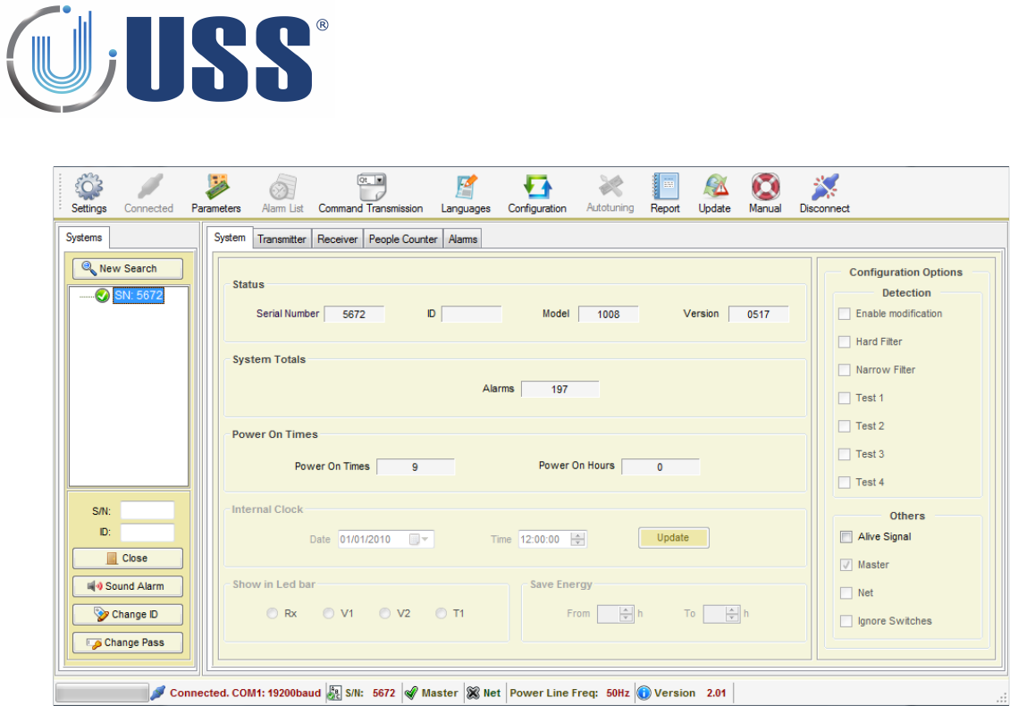
4.6. SYSTEM TAB........................................................................................................................................22
4.6.1. STATUS.......................................................................................................................................22
4.6.2. SYSTEM TOTALS..........................................................................................................................22
4.6.3. POWER TIMES.............................................................................................................................22
4.7. TRANSMITTER TAB..............................................................................................................................23
4.7.1. START / STOP TX........................................................................................................................23
4.7.2. DISCOVERY TOOL.......................................................................................................................24
4.8. RECEIVER TAB....................................................................................................................................24
4.8.1. GAIN..........................................................................................................................................28
4.8.2. THRESHOLD...............................................................................................................................28
4.8.3. RX OSCILLATOR.........................................................................................................................28
4.8.4. SIGNAL AND NOISE ...................................................................................................................29
4.9. ALARMS TAB.....................................................................................................................................30
4.9.1. SOUND OPTIONS.......................................................................................................................30
4.9.2. RS232 ALARMS..........................................................................................................................30
2

4.10. CUSTOM SETUP...............................................................................................................................31
4.10.1. CUSTOMIZING INSTALLATION PROCESS...................................................................................31
4.10.2. CUSTOMIZING SOFTWARE ICON..............................................................................................31
5.
SAVETY AND DECLARATIONS.....................................................................................................................32
5.1. SAVETY GUIDELINES..........................................................................................................................32
5.2. FCC DECLARATION.............................................................................................................................32
3

1. SYSTEM OVERVIEW
1.1 Description
USS 58kHz Deactivator can detect and deactivate any electronic resonant circuit at 58 kHz or any acousto magnetic
tag passing through the detection area. The device also provides visual and audible alarm confirming the
deactivation is successful.
The system includes Digital Processing System (DPS) in order to achieve a great detection range, filtering noise and
achieving up to 15cm detection/deactivation range.
The tuning is done easily via powerful software. The system can be accessed via laptop.
1.2 Specifications S
1.2.1. TRANSCEIVER
ELECTRICAL
MECHANICAL
Operating Frequency
58 kHz
EXTERNAL BORDER
INTERNAL BOX
Transmit Burst Duration
0.5ms or 1.5 ms
Height
52mm
42mm
Transmit Burst Repetition Rates
Width
254mm
234mm
150Hz (TX burst 0.5ms)
Depth
244mm
224mm
75Hz (TX burst 1.5ms)
Weight
3kg
50Hz (TX burst 1.5ms)
Transmit coil Resistance
1.5 Ohm
1.2.2. POWER SUPPLY
ELECTRICAL
ENVIROMENTAL
Primary Input
230Vac / 110Vac
R. Humidity
0 to 85% non condensing
Output #1
12 VAC
Operating Temperature
0º to 50º C
Output #2
20 VAC
Noise level
30dBm
Fuse
500mA Slow / 250V
4
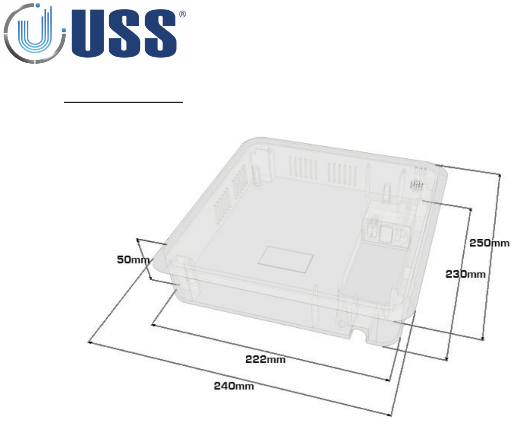
11.3 Device MeasurementsS
5
2. HARDWARE
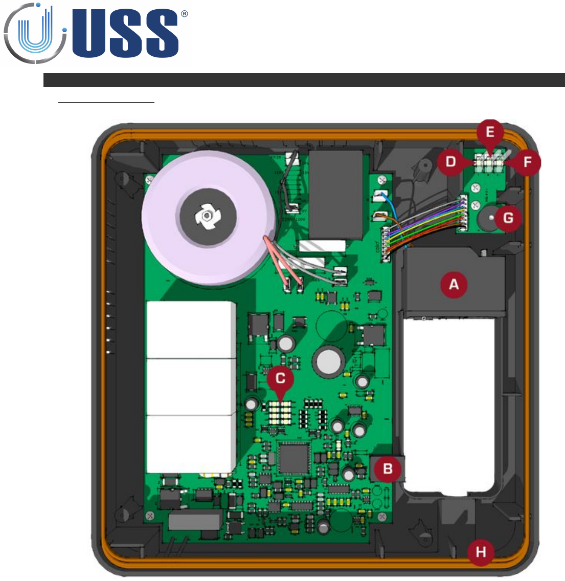
2.1 Transiever BoardRD
A: POWER INPUT
B: COMMUNICATION RS232 RJ45
C: LED SIGNAL BAR
D: DEACTIVATION CONFIRMATION (RED)
E: DEACTIVATING (RED FLASHING)
F: POWER ON (GREEN)
G: ALARM (BUZZER)
H: ANTENNA
6

3. QUICK TUNING
3.1 Quick Installation
3.1.1. PREVIOUS
Install the deactivator the same way as a system installation
Always connect the device to clean power lines (No other electrical devices connected)
Always turn on systems/deactivators ONE by ONE. Once you have tuned the first one, THEN connect the
second one, THEN the third, etc…Do not fix the system to the floor before testing its performance FIRST!
Do not fix the device before testing its performance FIRST!
Read this manual BEFORE installing deactivators!
3.1.2. DEACTIVATOR INSTALLATION
Check cabling / connection needs according to the kind of installation. Check all the material is ready.
Place the deactivator in the installation area.
Turn the deactivator ON, and connect it
Check Electrical Noise, Synchro, TX Status, etc… check everything is normal
Stabilize external electrical noise to the minimum.
IN ORDER TO AVOID FALSE DEACTIVATIONS, TUNE THE DETECTION DISTANCE (THRESHOLD, GAIN) TO BE
LESS THAN THE DEACTIVATION DISTANCE (DEACTIVATION VOLTAGE).
If any modifications, save parameters.
Disconnect your laptop and observe the deactivator during some time making several
detection/deactivation tests.
If OK, fix the deactivator, if not OK, see Section 3.2 TROUBLESHOTING
You are done!
3.2 Troubleshooting
3.2.1. NO DETECTION
Try with other tag
Rise Gain (Up to 2-3 LEDS)
Lower Threshold
See Section 3.4. NOISE PROBLEM
See Section 3.3. SYNCHRONIZATION PROBLEM
3.2.2. TOO MUCH DETECTION
Lower Gain
Rise Threshold
3.2.3. FALSE ALARM
Look for TAGS near the antennas
See Section 3.5. FALSE ALARM (OR UNKNOWN ALARM)
3.2.4. MAKES OTHER SYSTEMS FALSE ALARM
See Section 3.3. SYNCHRONIZATION PROBLEM
7
3.3 Synchronization Problem
How can I recognize a synchro problem?
Externally: When you turn on your system:
•It makes other 58 kHz systems near alarm
•Your system is showing a high amount of noise in the LED bar (See Section 2. HARDWARE ).
•There is no detection or it is very poor.
Laptop:
•Check Section 4.7.4. DISCOVERY TOOL
How can I know the synchro problem has been solved?
Externally all systems around will be working fine as well as yours.
Laptop: The situation in the discovery mode will be similar to this:
You are done!
8
3.4 Noise Problem
How can I recognize a noise problem?
Externally: When you turn on your system:
•The system shows a high amount of noise in the LED bar.
•The detection might be poor.
Laptop:
•In the scope you will see high amount of noise, in the 2 buffers.
How can I solve a noise problem?
Try to locate the source of noise:
•Turn off all electrical equipment in the area. If the noise disappears, start turning all the electrical
equipment ONE BY ONE till you get noise again.
•Other way to locate the source of noise is moving the deactivator while at the same time you are
looking to the LED bar or the software. See how the orientation of the antenna affects the amount of
noise and you will finally find the source.
Then you have to neutralize the source of noise. (It might be related with bad synchro, please check
procedure in Section 4.7.4. DISCOVERY TOOL
How can I know the noise problem has been solved?
Detection will improve. The signs of noise in the LED bar and in the scope will disappear.
You are done!
9
33.5 False Alarm or Unknown Alarm
How can I recognize a false alarms (or unknown alarm) problem?
Your deactivator is alarming when not expected to alarm. Deactivator devices are very false alarm
restrictive. It is almost impossible that a deactivator device is alarming except when:
There is a tag in the detection area
There is another 58 kHz system or deactivator not in synchro.
How can I solve a false alarms (or unknown alarm) problem?
Look for tags near the system. Look in the scope in the software. If you see something similar to this:
There might be another 58 kHz system or deactivator out of synchro affecting our device. Follow procedure
in Section 4.7.4. DISCOVERY TOOL
How can I know the false alarms (or unknown alarm) problem has been solved?
The system is working normally, no unexpected alarms.
You are done!
10

4. SOFTWARE
The interface of Remote Tuning Software for 58 kHz systems has been designed to allow an easy understanding of all
features. Icons are highly intuitive permitting a quick assimilation of concepts.
4.1 Installation ProcedureRE
Before installation verify that you have Windows98se or higher.
Close all the executing programs.
Run the installer
Select the folder to install the software and click on Install button
Run the software:
11
4.2 Connect
4.2.1. RS232 PORT
Use an USB to Rs232 adaptor if the computer which will be used to connect to the system does not have a
RS232 port.
Connect the communication cable provided to the USB adaptor or directly to the system if the computer
has RS232 port.
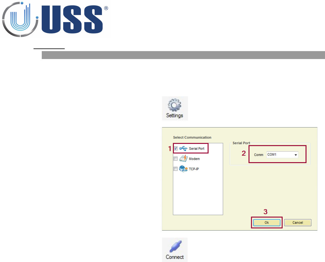
Run the software and press 'SETTINGS'
1. Select Serial Port Communication.
2. Select Serial Port Comm.
3. Press OK
Press Connect
The software will search for all the systems connected and load them into the System window
12
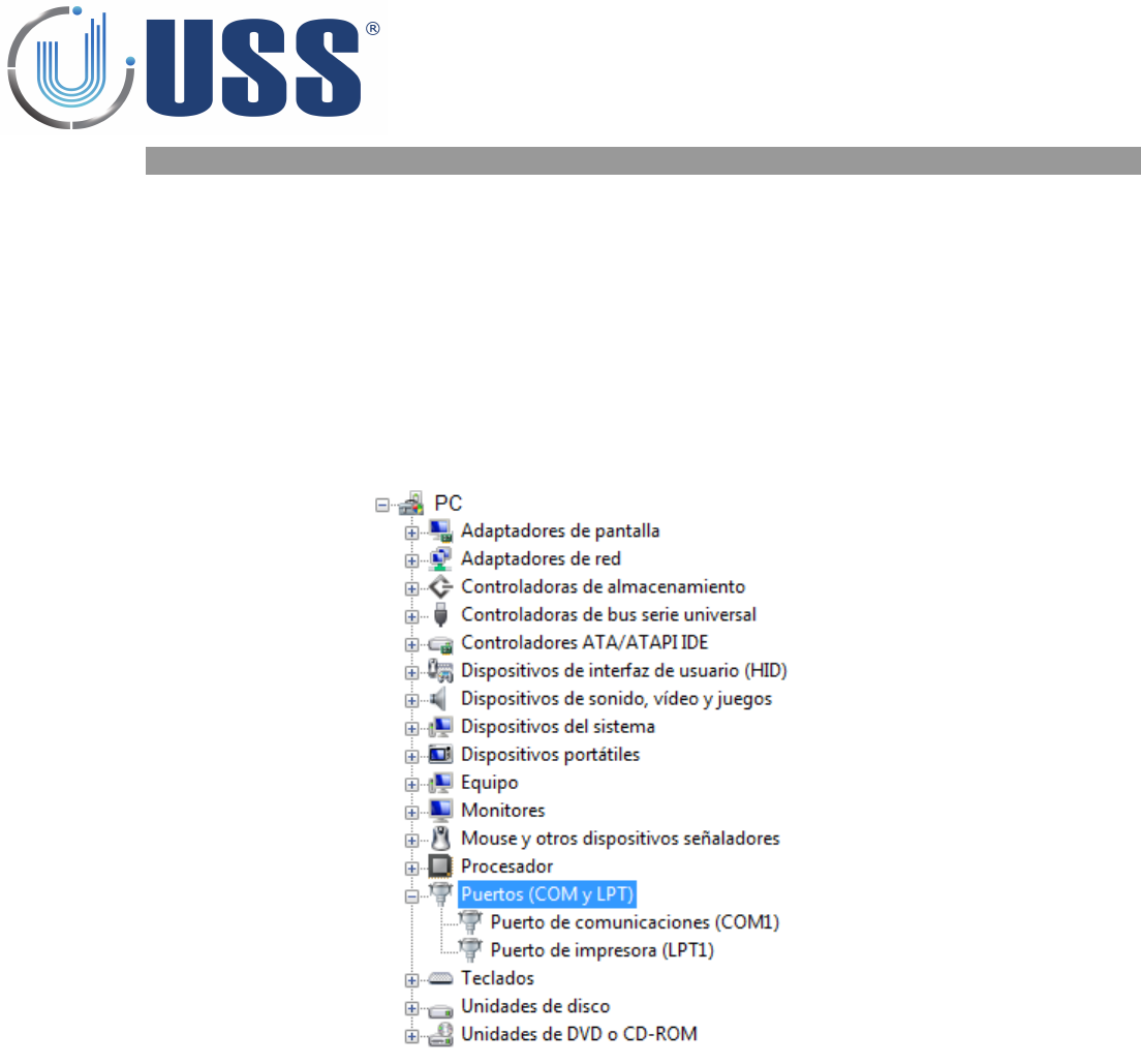
4.2.2. HOW TO KNOW THE COM PORT
If you are using a USB to RS232 adapter, check which virtual port is assigned by the adapter. To do this,
follow the steps:
•1. Click on Start and then Control Panel.
•2. Click on the Performance and Maintenance link.
•3. Note: If you're viewing the Classic View of Control Panel, you won't see this link. Simple double-click
on the System icon and proceed to Step 4.
•4. In the System Properties window, click on the Hardware tab.
•5. With the Hardware tab selected, click on the Device Manager button.
•6. Select Ports (COM & LTP) and check port name used for the adapter.
13
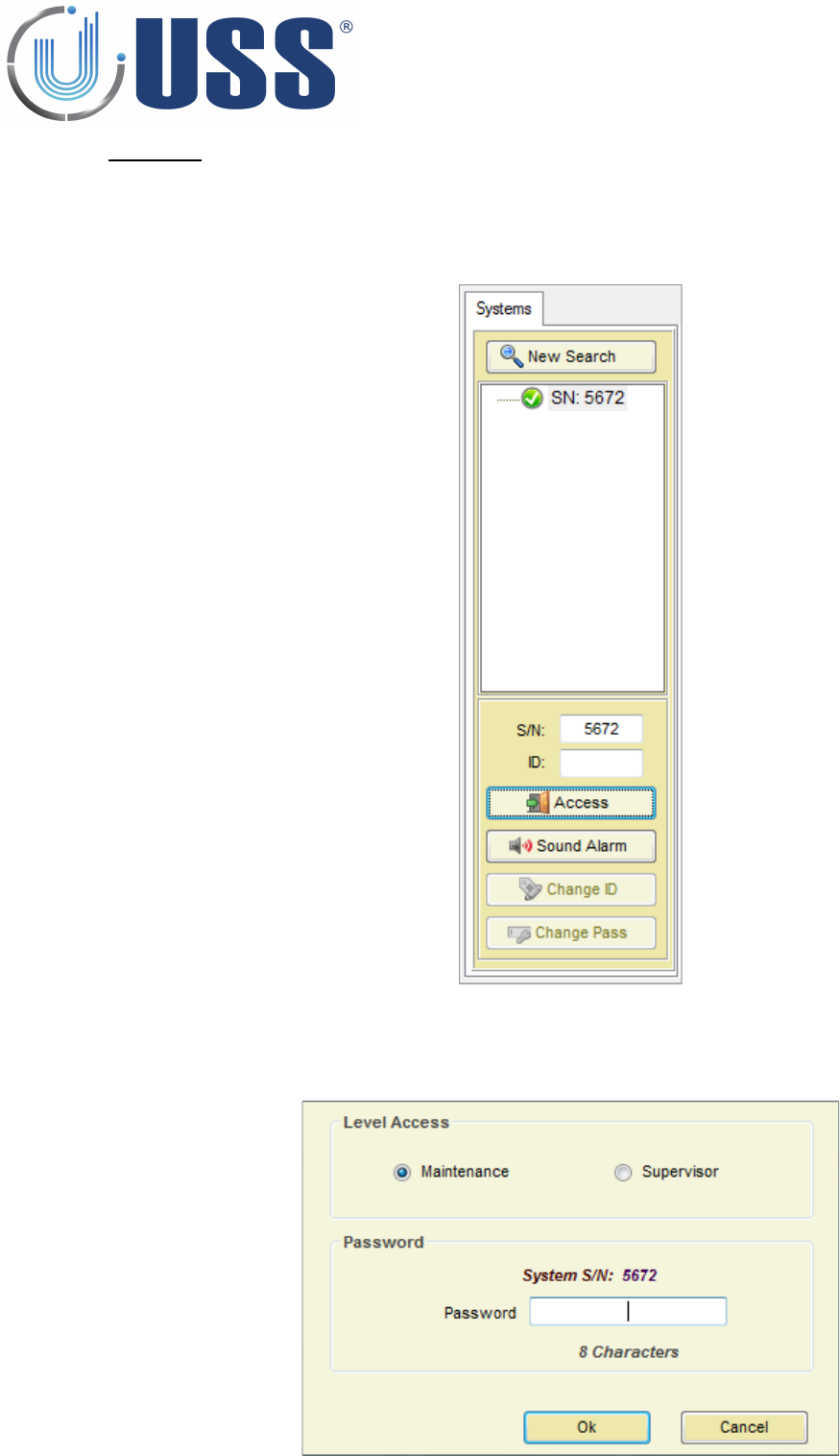
4.3 Access
To access any of the systems in the line it is ONLY necessary to connect the PC/LAPTOP/MODEM/TCP-IP
MODULE to the MASTER. You gain access to all the slaves through the master.
Double click the SN of the system you want to gain access.
Select Maintenance / Supervisor access
Input PASSWORD (Factory 12345678 for Maintenance)
Press OK
14
The selected system is accessed
15
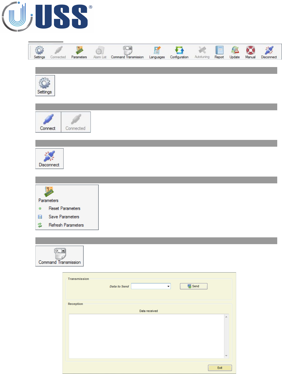
4.4 Main MenuNU
4.4.1. SETTINGS
Gain access to the connection settings menu
4.4.2. CONNECT /CONNECTED
Connect to the system(s)
If the connection is active, then it is shown as 'Connected'
4.4.3. DISCONNECT
Disconnect from the accessed system
4.4.4. PARAMETERS
Reset all parameters in the system to factory values
Save all parameters in the system
Refresh all parameters in the software from the system memory
4.4.5. COMMAND TRANSMISSION
Opens Command Transmission window to input any command directly
to the system
16
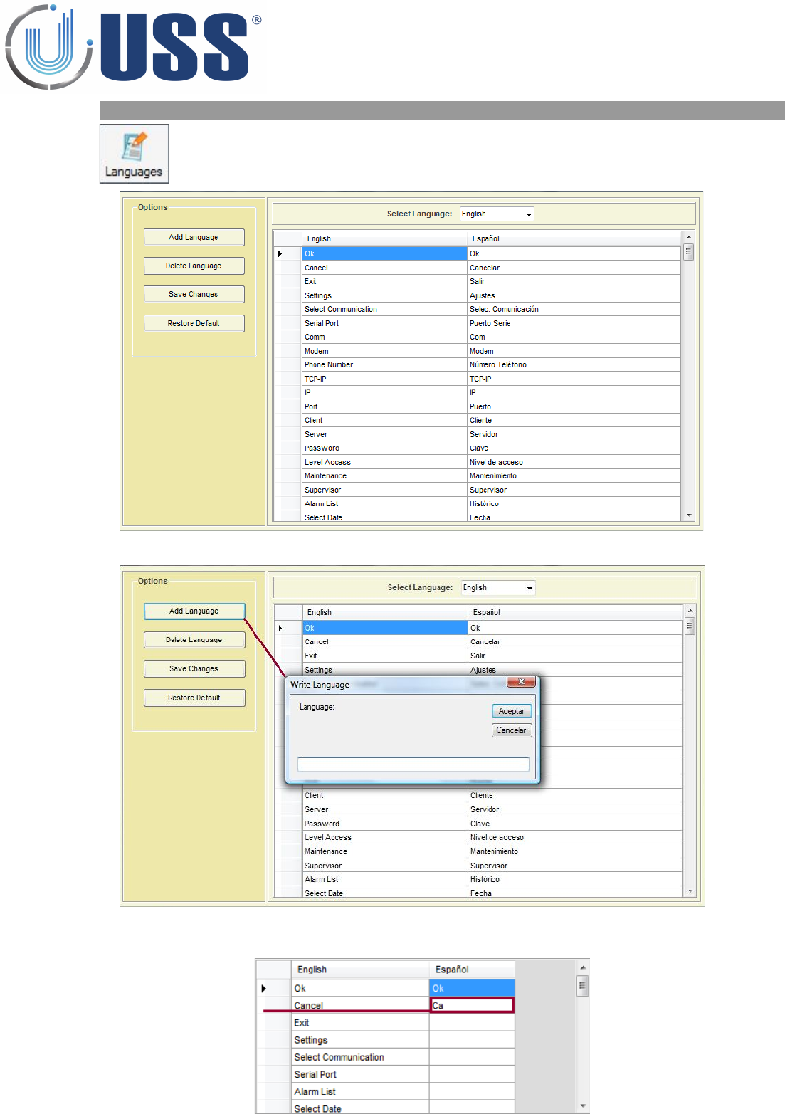
4.4.6. LANGUAGES
All labels are supported in other languages. You can add new language
or delete it.
Add language
Write all the words you need.
Save the changes and select the language.
17
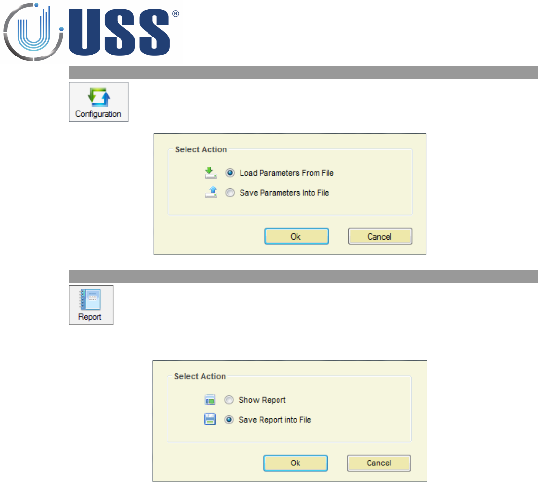
4.4.7. CONFIGURATION
The parameters can be saved into a file and then loaded when necessary
4.4.8. REPORT
Displays all the system measurements and parameters saved on a file at a
certain moment.
Select Save Report into File in order to save all the parameters and measurements from the system:
Click Ok.
18
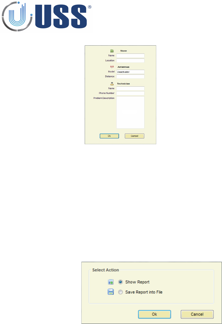
Optionally, you can set the following information from the store and the system:
Click Ok and give a name for the Report file
To display a report, select Show Report option, click Ok button and select the report file.
19
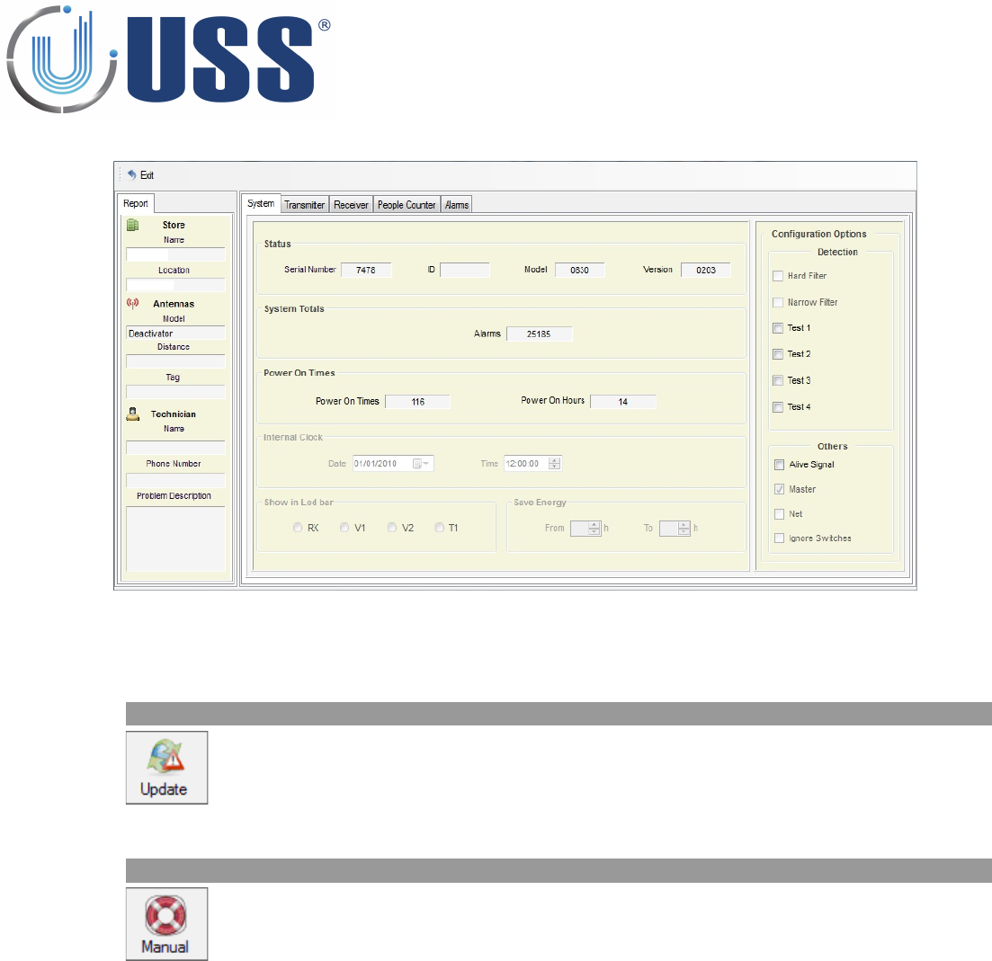
The Report will show up as follows:
Information of System, Transmitter, Receiver and Alarms will be showed up.
4.4.9. UPDATE
Click on Update Menu to check for new versions available.
4.4.10. MANUAL
Click on Manual Menu to browse Tuning G10V Manual
20
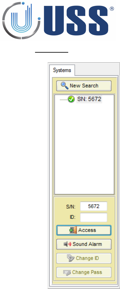
4.5 Systems
Options for this section:
•Start a new search to load the systems
•Visualization of systems found with their Serial Number and ID
•Close access or get access to selected system
•Sound the alarm of selected system
•Change ID of selected system (once you gain access)
•Change password (once you gain access)
21
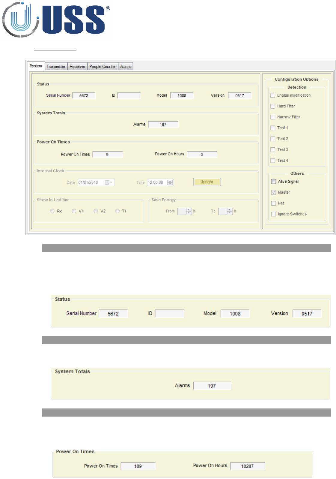
4.6 System Tab
4.6.1. STATUS
The following information can be found: (Only INFO)
•Serial Number
•Current ID
•Model
•Version
4.6.2. SYSTEM TOTALS
The following information can be found:
•Total number of Alarms
4.6.3. POWER TIMES
The following information can be found:
•Total number of Power ON
•Total Number of Power ON hours (working hours).
22
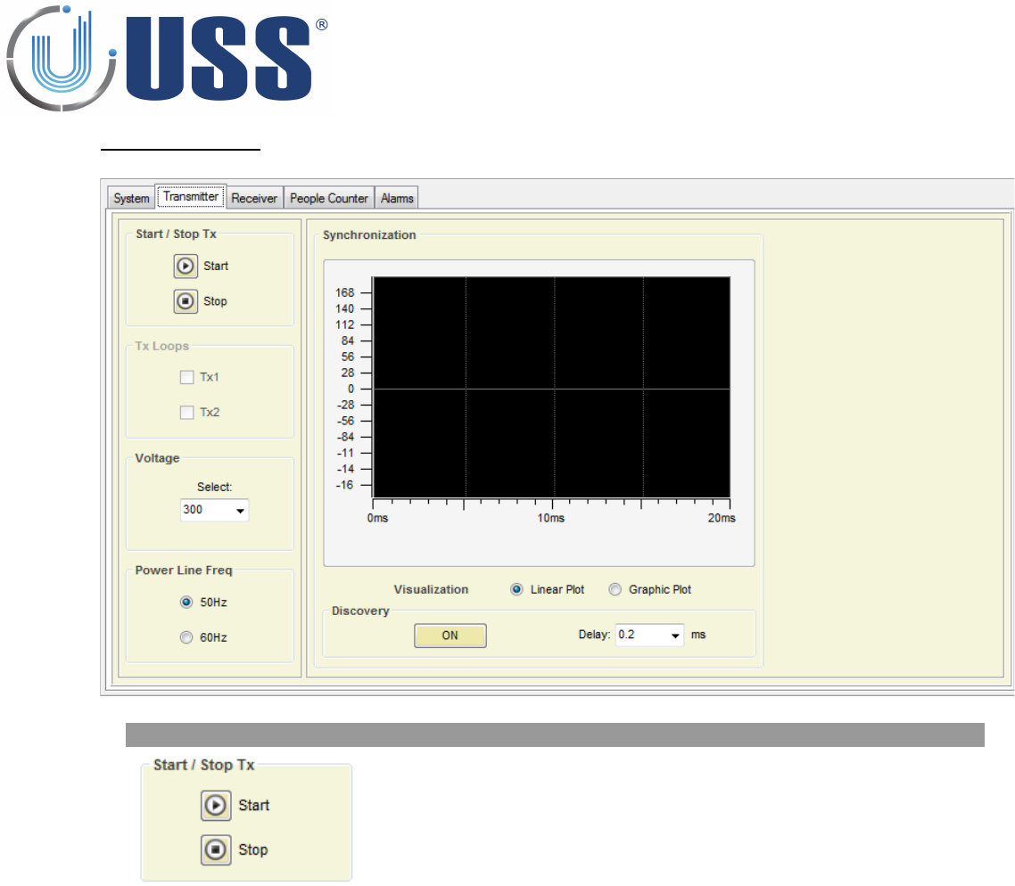
4.7 Transmitter Tab
4.7.1. START / STOP TX
Transmission can be stopped, this can be used to confirm if an alarm is
coming from tags / labels.
If the Transmission is stopped and the alarm stops, then the alarm was
caused by a tag.
23
4.7.2. DISCOVERY TOOL
Main tool to synchronize the system.
In 99% of cases this adjustment is not necessary. Anyway, it is always good to take a look at the
environmental electric noise throughout the “Discovery Mode” feature.
When Discovery Tool is ON, the transmitter is then turned off, and the system ONLY receives.
Standard Synchro delay value is 0.2ms
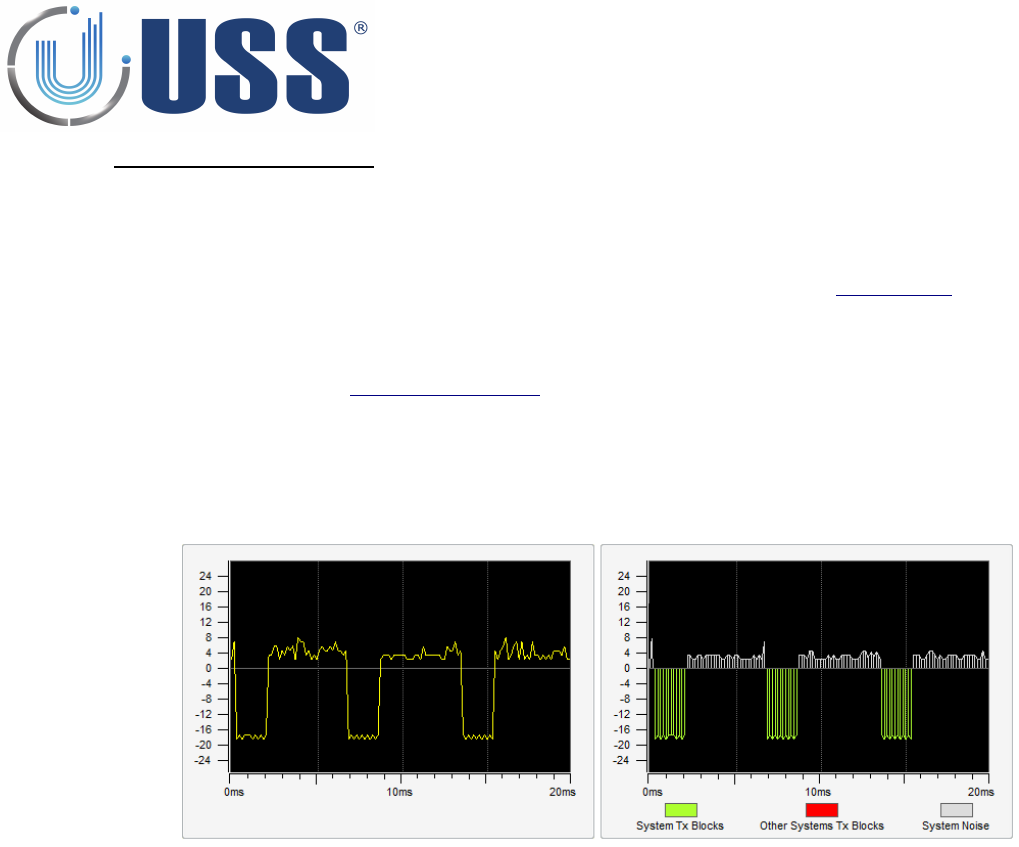
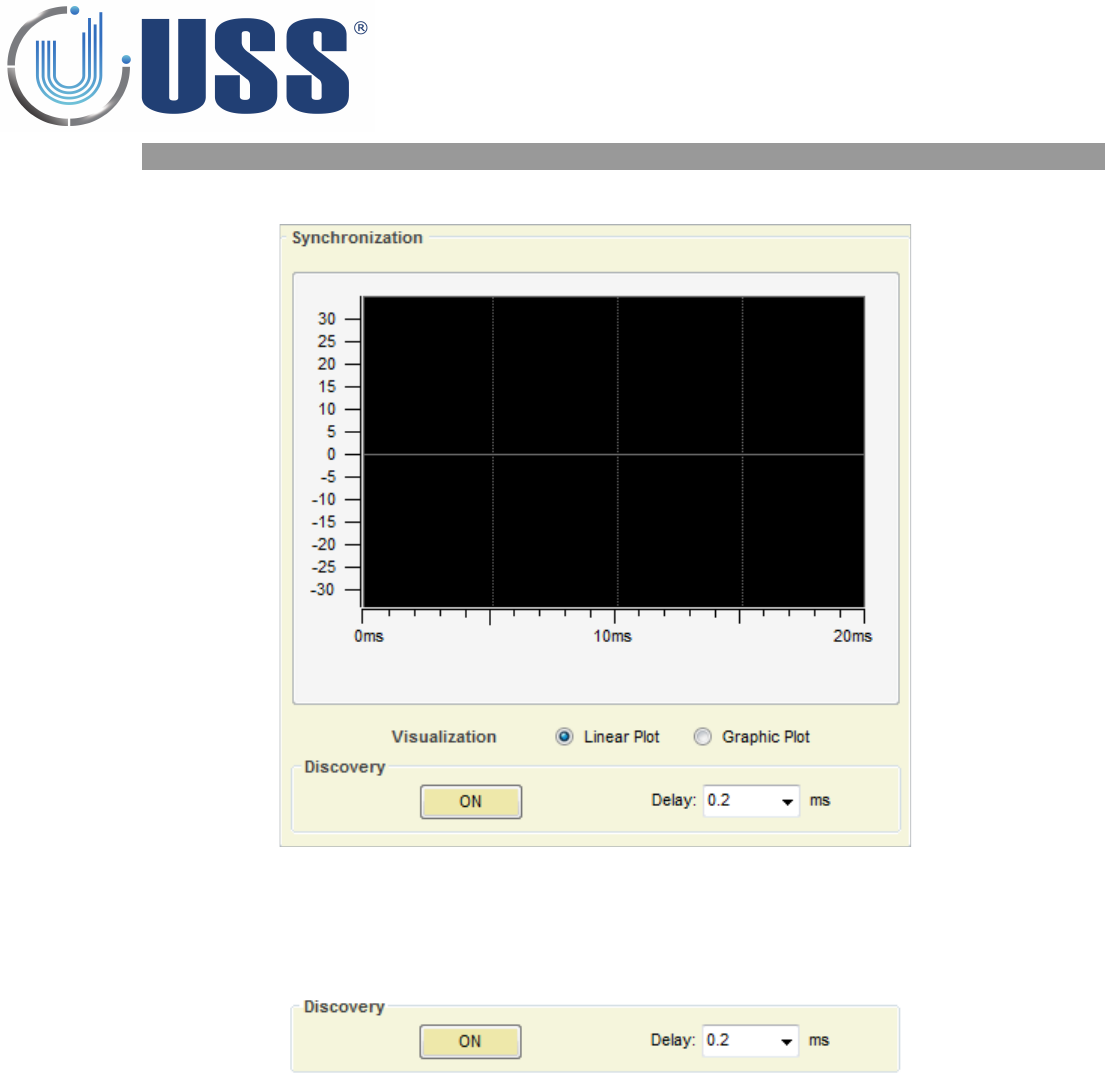
Once the Discovery Tool is ON, electrical noise and other possible systems out of phase are shown on the
screen. In the scope is represented the amount of noise in 58 kHz through the 0º phase to the 360º phase
in the mains. (From 0 ms to 20 ms in one 50 Hz period).
In the scope, the TX blocks will be represented in the lower side of the yellow line (negative), the TX blocks
of other systems out of phase, will be represented in the upper side of the yellow line (positive).
24
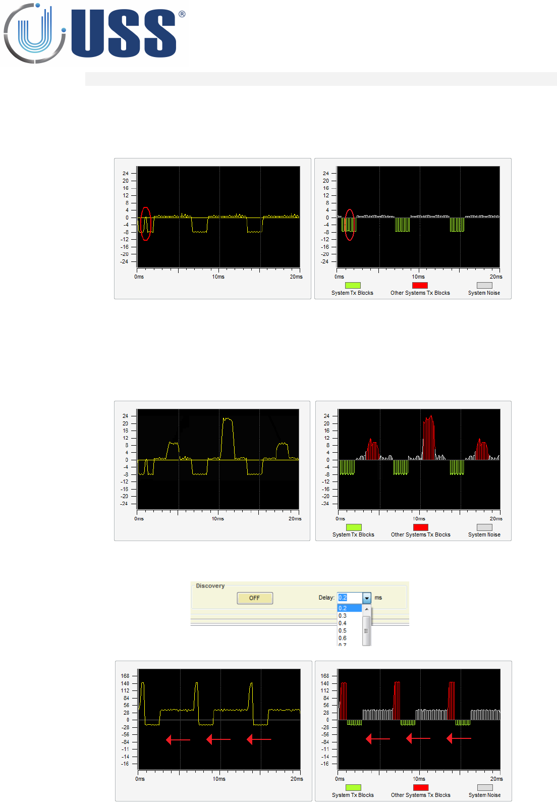
FIELD SITUATIONS
1. Systems perfectly in phase (99% of times), NO NEED TO SYNCHRONIZE
•In these cases, only the blocks in the lower part can be seen. The presence of another system which is
correctly synchronized with yours, can be seen in the break of the first block (RED CIRCLE)
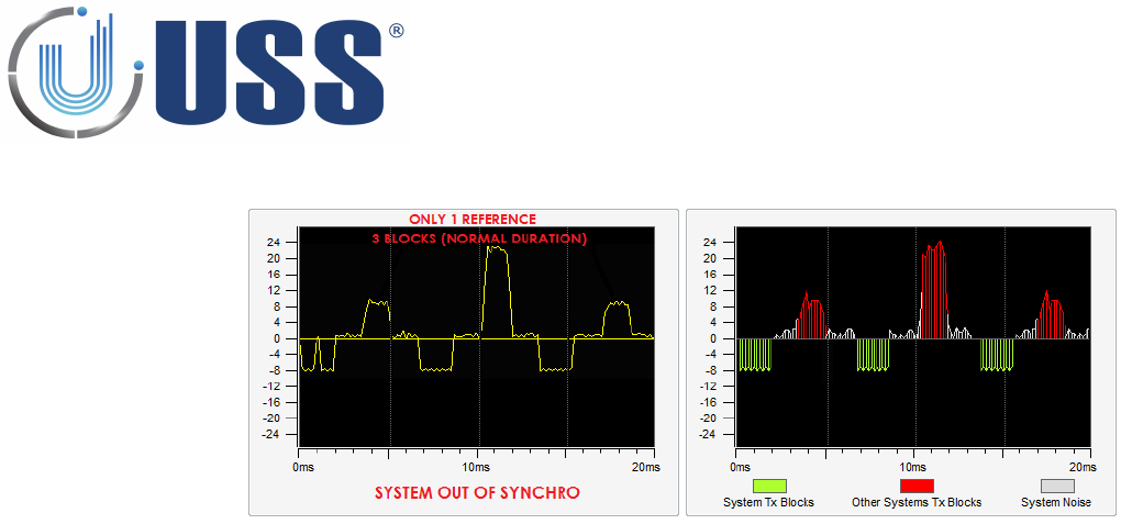
2. Systems out of synchro, NEED TO SYNCHRONIZE, Only one external reference
•When another 58 kHz transmitter is transmitting out of synchro, it can be easily seen from the scope
screen. The area above the yellow line is reserved for these situations. In the next figure, the presence
of another 58 kHz transmitter can be easily seen on that area. Only one external reference means that
only 3 TX blocks from other system can be seen in the upper side of the screen.
•Change the delay manually to synchronize with the system out of synchro.
25
•Match the systems transmissions with one each other…
•As it can be seen on the figure above, our TX blocks (below yellow line) have moved until the position of
the other system TX blocks. The synchro can be followed and verified visually. The peaks appearing in
the 2 last blocks (RED CIRCLE) are normal when the system is too near.
•After a good synchronization process, you must turn Discovery Mode off, to do so press OFF
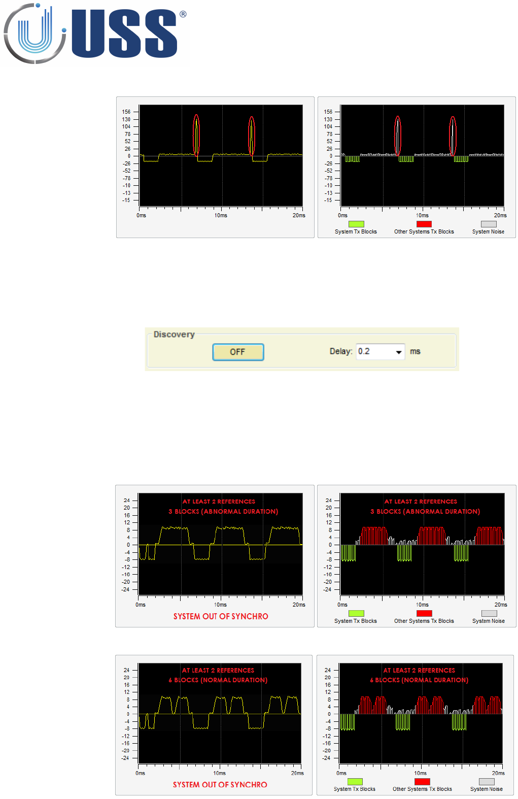
3. Systems out of synchro, NEED TO SYNCHRONIZE, More than one external reference
•When there is more than one reference to synchro, then a correct synchronization is not possible. This
means that previous to the installation, there were already at least 2 systems out of synchro, probably
these systems are already not working. In order to fix the problem it is necessary to previously
synchronize between them the existing systems.
•6 blocks of normal duration, means at least 2 previously not synchronized systems
•3 blocks of abnormal duration, means at least 2 previously not synchronized systems
26
•After synchronizing ALL external systems, the situation will be as follows:
•Then the system can be correctly synchronized using this unique and only external reference.
•Please follow step CASE 2, to synchronize de system in accordance.
27
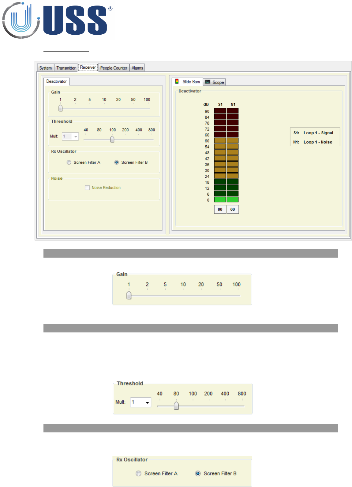
4.8 Reciever Tab
4.8.1. GAIN
Gain feature is used to adjust the receiver sensitivity to get the best reception signal.
In order to adjust Gain, simply select the value until you get the required detection.
4.8.2. THRESHOLD
Threshold feature is the signal level at which each receiver will trig an alarm.
A Higher threshold means less sensitive for the system, more quantity of signal will be needed from the tag
to trigger an alarm, the detection is reduced.
It is recommended, for maximum sensitivity to keep the Detection Threshold at minimum (40)
In order to adjust Detection Threshold, simply select the value until you get the required detection
4.8.3. RX OSCILLATOR
In some cases (Noise coming from a TFT or plasma), swapping between USB or LSB filter will help to reduce
electrical noise.
28
NOTE:
This setting is set to 1
and can't be changed
in USA
Note :
This is set to B
and can't be
changed in USA
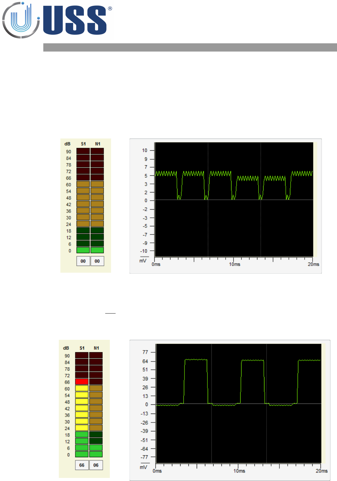
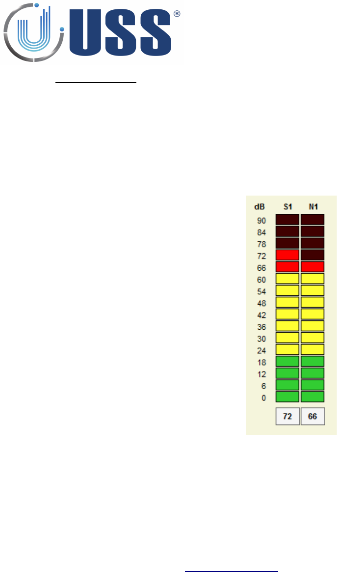
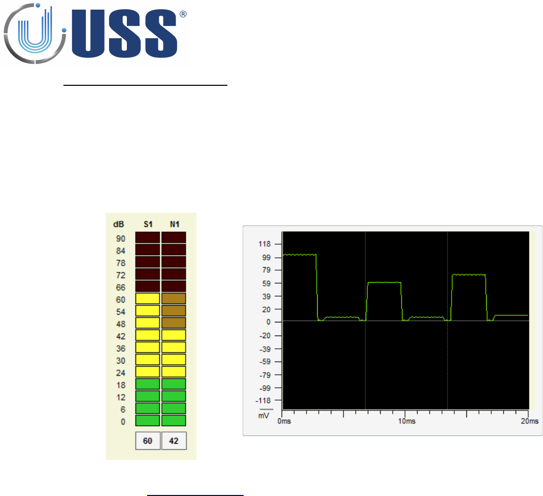
4.8.4. SIGNAL AND NOISE
In the scope area there is a digital oscilloscope display that will help to analyse the noise and signal. Real
time electrical noise signals icon will show current electrical signal (Noise and tags if there is any).
There are 2 different reception areas shown on the Signal Bars / Digital Scope: 'Loop 1 Signal' and 'Loop 1
Noise'
•SITUATION 1 (When there is no tag near)
The reception areas shown on the Signal Bars / Digital Scope should look as follows:
In the 2 different reception Bars/Areas, only electrical noise in the environment is shown, as there is no
tag near.
All 2 reception Bars/Areas MUST HAVE SIMILAR values.
•SITUATION 2 (When there is a tag near)
The reception areas shown on the Signal Bars / Digital Scope should look as follows:
In the 2 different reception Bars/Areas, the reception Bar/Area reserved for noise keep the same as in
SITUATION 1 BUT the Bar/Area reserved for tag signal, show higher values than the one reserved for
noise.
This way, an alarm caused by tags can be easily identified.
29
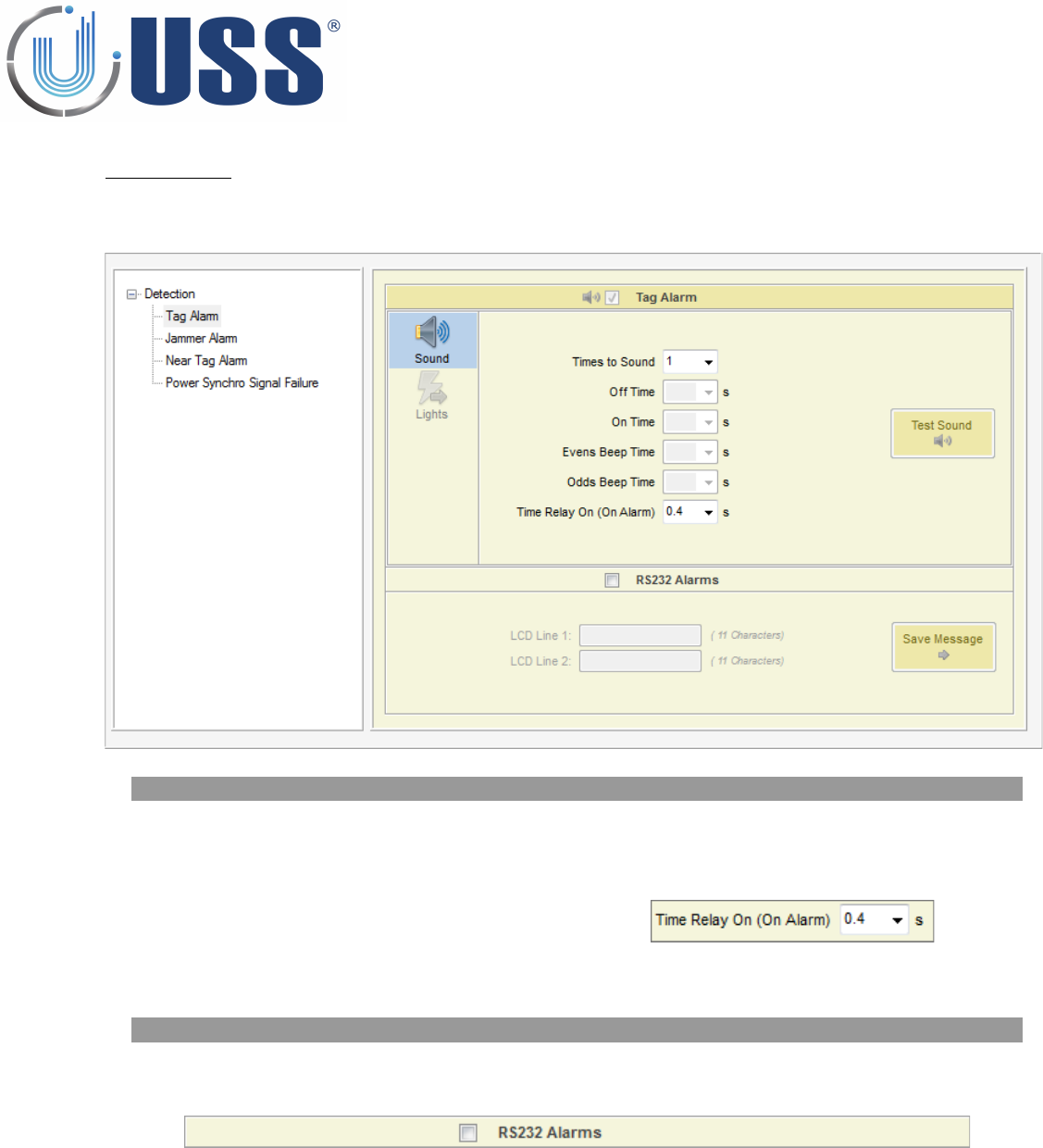
4.9 Alarm Tabs
This section allows you to configure the alarm in the system.
4.9.1. SOUND OPTIONS
Select number of times to sound and customize beep duration time.
Relay
•When an alarm occurs, the alarm closes a relay and
triggers anything connected to it.
•RELAY SPECIFICATIONS: 240V & 250mA.
•Normal Open(NO) & Normal Close(NC) contacts
4.9.2. RS232 ALARMS
Receive a message via RS232 when an alarm is triggered
Click on the icon to enable or disable
30
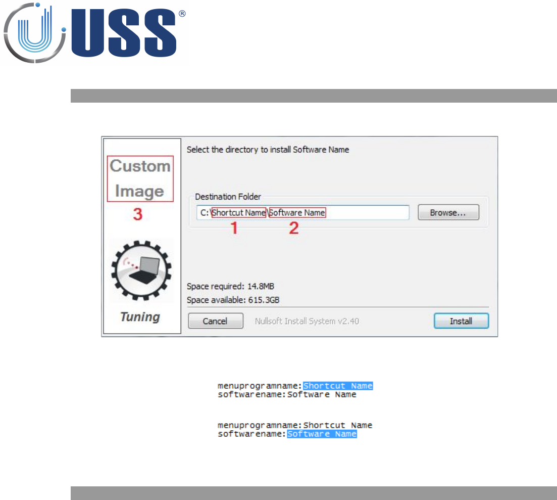
4.10.1. CUSTOMIZING INSTALLATION PROCESS
Customize the way installation setup runs including software name, shortcut on the start menu and display
settings:
Open the file InstallerConf.txt from the Installation package.
•1. Enter a name for the shortcut on the start menu after the text: “menuprogramname:”
•2. Enter a name for the software after the text “softwarename:”
3. Open the file InstallerLogo.bmp from the Installation package and customize the image for the
installation process.
4.10.2. CUSTOMIZING SOFTWARE ICON
Replace the icon from the InstallerIco.ico file located at the Installation package with the new icon you
want to use for the software.
31

5.
SAFETY AND DECLARATIONS
5.1 Safety Guidelines
Any manipulation of the system should be done BY QUALIFIED AND TRAINED personnel ONLY.
Power Supply gets 220V 50Hz (Europe) 110V 60Hz (USA & Canada) AC from Power Source. Transceiver
Antenna may hold high Voltage and current when working. To change blown fuses or manipulate antennas
ALWAYS UNPLUG from power source (mains).
Do not use the system in water condensing conditions. Do not use the system in explosive environmental
conditions.
32
5.2 FCC Declaration
“This equipment has been tested and found to comply with the limits for Class A digital device
pursuant to Part 15 of the FCC Rules. These limits are designed to provide reasonable protection
against harmful interference when the equipment is operated in a commercial environment. This
equipment generates, uses, and can radiate radio frequency energy and, if not installed and used in
accordance with the instruction's manual, may cause interference to radio communications.
Operation of this equipment in a residential area is likely to cause interference in which case the user
will be required to correct the interference at his own expense. The user is cautioned that changes and
modifications made to the equipment without approval of the manufacturer could void the user’s
authority to operate this equipment.”