Universal Surveillance Systems USS-MRG-82-400 8.2 MHz Mirage System User Manual MONO82 USR MAN REV 0A
Universal Surveillance Systems, LLC 8.2 MHz Mirage System MONO82 USR MAN REV 0A
User Manual
MONO 8.2 MHz (MONODSP8)
USER'S MANUAL
HISTORY OF REVISIONS AND REPAIRS:
07/2012 REV.A (HW:N:6163, REV.8.3; SW:V3.4)
Confidential and proprietary information, for internal use only.
MONO82_USR_MAN_REV_A
2
MONO82_USR_MAN_REV_A
This document was created to provide intended recipient documentation of requested device for technician purposes only. Any other usage of this document is an illegal and unlawful act. This document is a confidential and pro prietary
document of Universal Surveillance Systems and consist of i nformation what can be protected by copyrights or the others intellectu al property protection instr um ents of the others subjects. All other information, what are not generally
known ones, is an intellectual property of Universal Surveillance Systems. This document including any and all attachmen ts hereto is intended solely to be used by individual or entity to which it is addressed. If the reader of this
document is not the intended recipient, or an employee or agent responsible for delivering this document to its intended recipient, you are herewith notified that any dissemination, distribution, copying or retention of this document
or the informa tion contained her ein is strictly prohibited. If you have received this document in error, please notify us at service@u nivse ralea s. com immedia tely and permanen tl y delete or/and destroy the original and any copy or
printout thereof.
USER'S MANUAL
CONTENT
1. Safety guidelines 3
2. Basic information 3
3. El. board description (HW: N: 6163, REV.8.3; SW: V3.4) 4
4. Antennas 5
5. Connecting the el. board 5
6. RF application 8,2MHz MIX V3.4 6
6.1 Settings 7
6.2 System 7
6.3 Alarm 7
6.4 MONO 8,2MHz 8
6.4.1 Synchronization 8
6.4.2 TX 9
6.4.3 RX 9
6.5 Sync 10
7. Quick installation guide 11
7.1 Pre-installation 11
7.2 Basic equipment required 11
7.3 Configuration 12
7.4 Connection 12
7.5 Application settings 12
7.6 Final 14
8. Declaration 15
8.1 Equipment modification caution 15
8.2 FCC compliance 15
9. Notes 16
3
MONO82_USR_MAN_REV_A
This document was created to provide intended recipient documentation of requested device for technician purposes only. Any other usage of this document is an illegal and unlawful act. This document is a confidential and pro prietary
document of Universal Surveillance Systems and consist of i nformation what can be protected by copyrights or the others intellectu al property protection instr um ents of the others subjects. All other information, what are not generally
known ones, is an intellectual property of Universal Surveillance Systems. This document including any and all attachmen ts hereto is intended solely to be used by individual or entity to which it is addressed. If the reader of this
document is not the intended recipient, or an employee or agent responsible for delivering this document to its intended recipient, you are herewith notified that any dissemination, distribution, copying or retention of this document
or the informa tion contained her ein is strictly prohibited. If you have received this document in error, please notify us at service@u nivse ralea s. com immediately and permanen tl y delete or/and destroy the original and any copy or
printout thereof.
1. SAFETY GUIDELINES
Operate the system only as described in these operating instructions. Damage to
hardware
due
to improper use may result in loss of
warranty.
WARNING! Do not open the antenna el. board cover while it is connected to
main power. RISK OF ELECTRIC SHOCK!
CAUTION! When connecting or disconnecting antennas make sure that el. board
! is switched off.
CAUTION! Do not disconnect the connectors from el. board unless adapter has
! been disconnected from main power.
CAUTION! Only USS authorized professional technicians can install and/or service
! this system
2. BASIC INFORMATIONS
ABOUT: This reference manual settings procedure, basic tuning for put into operation of
the
MONO RF
8.2MHz electronic
board.
USE: The system MONO RF 8.2MHz electronic board is invented for protection of goods in
stores entry/exit and it works in frequency range of 8.2 MHz. MONO 8.2MHz detects all
kinds of tags from different producers, i.e. hard, soft and paper, which are intended for
radio frequency systems with
operating frequency
of 8.2 MHz. The system MONO 8,2MHz
consists of one mechanical pedestal and one electronic board. For higher number of
systems, synchronization is performed by a two-wire cable or wireless by the setting in RF
application. MONO 8.2MHz can operate even close to modern deactivators of paper tags
without any reduction of
sensitivity.
WORKING PRINCIPLE: Device transmits short high-frequency pulses and receives signals
from tags which are located in the detection field.
Radio-frequency
system is designed for
detection of RF tags and labels working on 8.2 MHz frequency. Detected tags activate
sound and light
alarm.
4
MONO82_USR_MAN_REV_A
This document was created to provide intended recipient documentation of requested device for technician purposes only. Any other usage of this document is an illegal and unlawful act. This document is a confidential and pro prietary
document of Universal Surveillance Systems and consist of i nformation what can be protected by copyrights or the others intellectu al property protection instr um ents of the others subjects. All other information, what are not generally
known ones, is an intellectual property of Universal Surveillance Systems. This document including any and all attachmen ts hereto is intended solely to be used by individual or entity to which it is addressed. If the reader of this
document is not the intended recipient, or an employee or agent responsible for delivering this document to its intended recipient, you are herewith notified that any dissemination, distribution, copying or retention of this document
or the informa tion contained her ein is strictly prohibited. If you have received this document in error, please notify us at service@u nivse ralea s. com immedia tely and permanen tl y delete or/and destroy the original and any copy or
printout thereof.
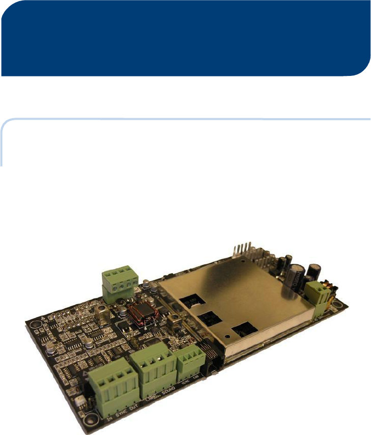
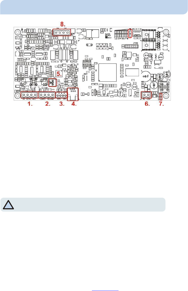
3. EL. BOARD DESCRIPTION (HW:N:6163, REV.8.3; SW:V3.4)
9.
Pic. 1 - El. board description
1.
-
Terminal of
external
synchronization from/into another el.
board. ( for install and
service only)
2. - Terminal that drive external speaker and LEDs or lights to provide audio and visual
alarms.
3. – Terminal is not used in the USA
4.
-
RS-232
interface ( for install and service only)
5.
-
Trimmer that adjust the
volume
of
external
speaker.
*NOTE
: This
is
the only manual tuning required for normal
installation!
*
6.
-
Terminal for power 15VAC supply, with consumption
of at
least
300mA.
7.
-
ON/OFF
power
LEDs
status.
8.
-
Transceiver antenna terminal drives two unicoil
antennas.
5
MONO82_USR_MAN_REV_A
This document was created to provide intended recipient documentation of requested device for technician purposes only. Any other usage of this document is an illegal and unlawful act. This document is a confidential and pro prietary
document of Universal Surveillance Systems and consist of i nformation what can be protected by copyrights or the others intellectu al property protection instr um ents of the others subjects. All other information, what are not generally
known ones, is an intellectual property of Universal Surveillance Systems. This document including any and all attachmen ts hereto is intended solely to be used by individual or entity to which it is addressed. If the reader of this
document is not the intended recipient, or an employee or agent responsible for delivering this document to its intended recipient, you are herewith notified that any dissemination, distribution, copying or retention of this document
or the informa tion contained her ein is strictly prohibited. If you have received this document in error, please notify us at service@u nivse ralea s. com immediately and permanen tl y delete or/and destroy the original and any copy or
printout thereof.
9. - Heartbeat LED - Blink slowly in normal run mode. Blink fast (for 9 sec.) when you turn
ON the electronic board or during the quick
adaptation
(for 4 sec.) (system adaptation to
environment interference)
or
during the
time when is
the Transmitter (TX)
turned
OFF.
4. ANTENNAS
The antennas that are connected with MONO RF 8,2MHz electronic board are always
configured as multicoil transceiver devices. They combine transmit and receive function
with one
pedestal.
*NOTE
: See section 6.5
MONO 8,2MHz ->
Synchro.
*
All settings about the antenna fine tuning and synchronization are performed in RF
application 8.2MHz MIX
V4.0.
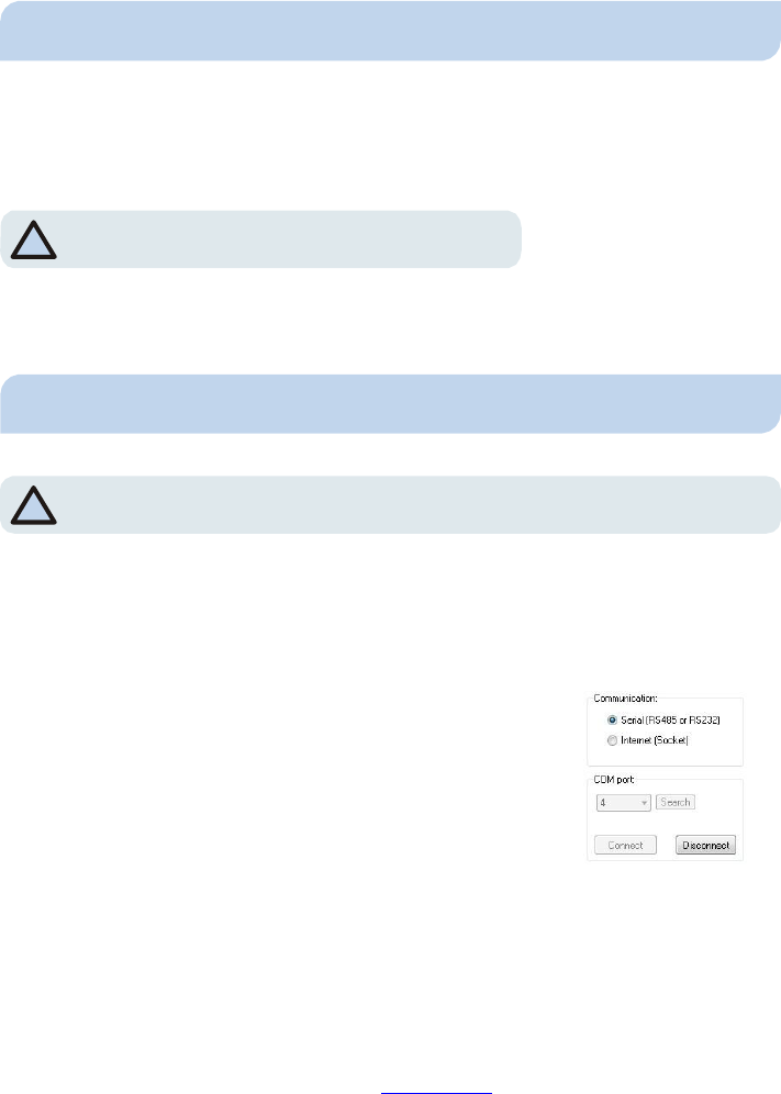
5. CONNECTING THE EL. BOARD
*NOTE: Please note that the device must be connected to the PC as long as you
*
keep configuring
it. Device is removed after configuration.
The MONO 8.2MHz system is configured and tuned mostly by software. The latest version
of RF application 8.2MHz MIX should be installed before connecting to the control box.
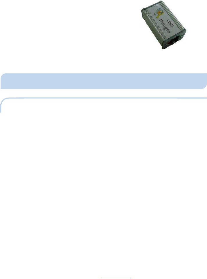
Electronic board is connected to the PC with a USB Hardware Key which is required for
security purposes
or with
eComm
via
internet connection.
When you start the application,
you will see
basic
connection settings
window.
Communication - Choose according to device which will
mediate the communication. Serial includes devices with
RS485 or RS232
interfaces,
that provides USB
connection
with
computer. Internet includes devices as eComm that provides
remote server control via internet
connection.
COM port - Choose number of USB port that is set for Serial
communication in you computer. If you are unsure of what Pic. 2 - Basic connection
settings window
6
MONO82_USR_MAN_REV_A
This document was created to provide intended recipient documentation of requested device for technician purposes only. Any other usage of this document is an illegal and unlawful act. This document is a confidential and pro prietary
document of Universal Surveillance Systems and consist of i nformation what can be protected by copyrights or the others intellectu al property protection instr um ents of the others subjects. All other information, what are not generally
known ones, is an intellectual property of Universal Surveillance Systems. This document including any and all attachmen ts hereto is intended solely to be used by individual or entity to which it is addressed. If the reader of this
document is not the intended recipient, or an employee or agent responsible for delivering this document to its intended recipient, you are herewith notified that any dissemination, distribution, copying or retention of this document
or the informa tion contained her ein is strictly prohibited. If you have received this document in error, please notify us at service@u nivse ralea s. com immedia tely and permanen tl y delete or/and destroy the original and any copy or
printout thereof.
COM port needs to be selected, click "Search" button and the application will scan and
display the
correct
one.
Socket communication - Here you can connect device remotely via internet connection
with information and login authorized from
provider of
eComm.
The
hardware
key is
connected
to the 6-pin
RS232 Serial connector
on the
control
unit and
then to an available USB port on the
PC.
Pic. 3 - Hardware key
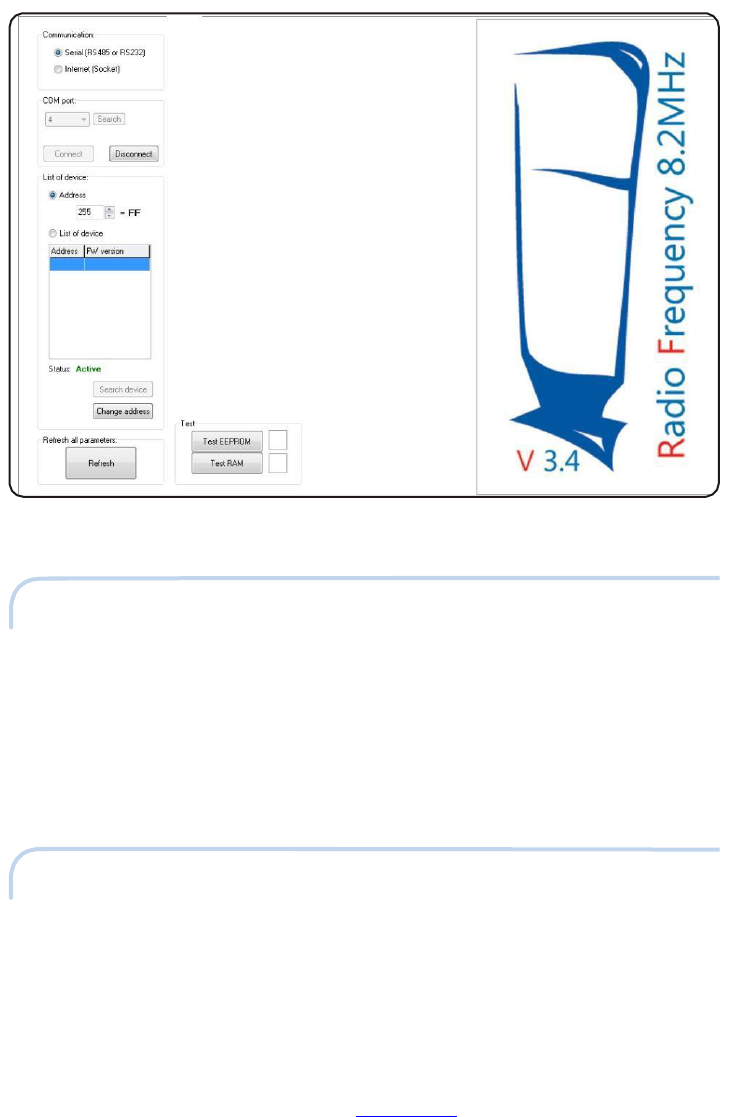
6. RF APPLICATION 8.2MHz MIX V3.4
6.1 SETTINGS
Settings page allows the user very basic control of the device as well as tests its
functionality.
Communication - Sets the type of communication, either locally or remotely through the
internet.
COM port -
Allows
the user to
select
the
correct
COM port
manually through
a
scroll
bar or
automatically by clicking on the “Search” button. The “Connect” button connects the PC
to the
device
locally or
remotely
and
“Disconnect” disconnects
it.
Make sure
to disconnect
the device before unplugging it to avoid freezing of the computer and/or loss of data.
List of device - Shows list of connected devices. Here you can also change the address of
device, simply with button "Change
address".
Refresh all parameters
-
Updates all
data from
the controller unit with the latest
values.
Test - Clicking on this buttons will test the EEPROM and RAM memory. If the memory is
broken, contact
manufacturer.
7
MONO82_USR_MAN_REV_A
This document was created to provide intended recipient documentation of requested device for technician purposes only. Any other usage of this document is an illegal and unlawful act. This document is a confidential and pro prietary
document of Universal Surveillance Systems and consist of i nformation what can be protected by copyrights or the others intellectu al property protection instr um ents of the others subjects. All other information, what are not generally
known ones, is an intellectual property of Universal Surveillance Systems. This document including any and all attachmen ts hereto is intended solely to be used by individual or entity to which it is addressed. If the reader of this
document is not the intended recipient, or an employee or agent responsible for delivering this document to its intended recipient, you are herewith notified that any dissemination, distribution, copying or retention of this document
or the informa tion contained her ein is strictly prohibited. If you have received this document in error, please notify us at service@u nivse ralea s. com immediately and permanen tl y delete or/and destroy the original and any copy or
printout thereof.
Pic. 4 - Settings window
6.2 SYSTEM
System parameters are for factory testing and modifications only. It is not recommended
to change
these values
without the
advice
of
manufacturer.
Software version - Shows the current version of the system and serves as important
information for any possible future
upgrades.
Device default setting
-
Returns
all
settings
that you make to the factory
settings.
6.3 ALARM
This page set up to three types of alarms. Each alarm is for different passing condition of
the
scanned
gateway.
8
MONO82_USR_MAN_REV_A
This document was created to provide intended recipient documentation of requested device for technician purposes only. Any other usage of this document is an illegal and unlawful act. This document is a confidential and pro prietary
document of Universal Surveillance Systems and consist of i nformation what can be protected by copyrights or the others intellectu al property protection instr um ents of the others subjects. All other information, what are not generally
known ones, is an intellectual property of Universal Surveillance Systems. This document including any and all attachmen ts hereto is intended solely to be used by individual or entity to which it is addressed. If the reader of this
document is not the intended recipient, or an employee or agent responsible for delivering this document to its intended recipient, you are herewith notified that any dissemination, distribution, copying or retention of this document
or the informa tion contained her ein is strictly prohibited. If you have received this document in error, please notify us at service@u nivse ralea s. com immedia tely and permanen tl y delete or/and destroy the original and any copy or
printout thereof.
Duration of alarm light - Number specifies the time (in seconds) of how long will be the
light alarm running after the
trigger.
Blink frequency
-
Sets
how fast will
be
the light alarm
blink.
Duration of alarm sound - Number specifies the time (in seconds) of how long will be the
sound alarm
running after the
trigger.
Beeper frequency
-
Changes the
speed interval of
beeps.
Type of beeps - You can choose between four types of beep intervals and assign them to
different types
of
alarms.
Test buttons
-
Serves for testing
of correct run of light and sound
alarms.
Watchdog - This counter may be very important as the device will automatically reboot
itself from time to time when it encounters an error. High number in short period of time
may indicate a problem with the
device. In that case contact
manufacturer.
6.4 MONO 8,2MHz
6.4.1 SYNCHRONIZATION
Synchro - Type of synchronization - Mains frequency - Follows the moment of zero
crossing from falling or rising edge based upon which transmit the signal. This option
allows you to make simple synchronization with other systems to avoid them from the
interference, that transmitting signal
is
delayed at the
desired time
(in microseconds).
Type of synchronization - Slave - System waits for synchronization pulses from "Master
unit". Set of “Slave delay measurement of
synchronization”
depending on cable length. In
case
of longer cable reduce
the
value.
Type of synchronization - Individual synchro - Manual settings of system transmitting
period. Use only in case of high interference from mains
power.

9
MONO82_USR_MAN_REV_A
This document was created to provide intended recipient documentation of requested device for technician purposes only. Any other usage of this document is an illegal and unlawful act. This document is a confidential and pro prietary
document of Universal Surveillance Systems and consist of i nformation what can be protected by copyrights or the others intellectu al property protection instr um ents of the others subjects. All other information, what are not generally
known ones, is an intellectual property of Universal Surveillance Systems. This document including any and all attachmen ts hereto is intended solely to be used by individual or entity to which it is addressed. If the reader of this
document is not the intended recipient, or an employee or agent responsible for delivering this document to its intended recipient, you are herewith notified that any dissemination, distribution, copying or retention of this document
or the informa tion contained her ein is strictly prohibited. If you have received this document in error, please notify us at service@u nivse ralea s. com immediately and permanen tl y delete or/and destroy the original and any copy or
printout thereof.
- Jitter - Generates random values (the order of microsecond)
and adds them to the phase delay. The setting helps eliminate
mains interference.
- Period - Sets the value of the manual settings of system
transmitting period. Parameter is changeable only when it is
"Individual synchro"
active.
6.4.2 TX
TX - TX power - Select the value using scrollbar and confirm it with button.
The transmit power can be minimum at level 2 and
maximum at level
7.
- Use sweep - Leave this function always enabled. System transmits in eight
frequencies in that case. This is important due to untuned labels in 8,2MHz
frequency. You can set the range of minimum and maximum frequencies, but it is
recommended
to
leave default
values.
Due to restriction on certain frequency bands by the FCC, 8.2MHz MONO system
does not transmit in the following bands:
Low frequency of forbidden band 1: 8.271 MHz
High frequency of forbidden band 1: 8.314 MHz
Low frequency of forbidden band 2: 8.342 MHz
High frequency of forbidden band 2: 8.435 MHz
- Label protective mode - Save label from high transmiting power near the antenna,
which can destroy the
label. Function temporarily reduces
the transmitting
power.
6.4.3 RX
RX - Gain - With scrollbar select the desire gain and confirms it with button. Higher gain
can increase received signal but also noise from environment. Recommended value
is 100.
Alarm counters
-
Display counted
alarms.
Quick adaptation - System make continual quick adaptations after the set time. This
button allow
you to make
adaptation
instantly.

10
MONO82_USR_MAN_REV_A
This document was created to provide intended recipient documentation of requested device for technician purposes only. Any other usage of this document is an illegal and unlawful act. This document is a confidential and pro prietary
document of Universal Surveillance Systems and consist of i nformation what can be protected by copyrights or the others intellectu al property protection instr um ents of the others subjects. All other information, what are not generally
known ones, is an intellectual property of Universal Surveillance Systems. This document including any and all attachmen ts hereto is intended solely to be used by individual or entity to which it is addressed. If the reader of this
document is not the intended recipient, or an employee or agent responsible for delivering this document to its intended recipient, you are herewith notified that any dissemination, distribution, copying or retention of this document
or the informa tion contained her ein is strictly prohibited. If you have received this document in error, please notify us at service@u nivse ralea s. com immedia tely and permanen tl y delete or/and destroy the original and any copy or
printout thereof.
RX channels - Shows received signal on eight channels. Frequency of each channel
depends on parameter setting of "Use sweep" and range of minimal and maximal
frequency.
If it is "Use sweep" turned ON,
frequencies
are
mathematically generated
from
minimal to maximal value. If it is "Use sweep" turned OFF, all of eight channels has the
same
value. Every channel
can
be
deactivated by the
checkbox.
Test and testing - For testing purposes. Capture values from the electronic board and
report on them. Bias values should be
around 2100, different values indicate
error.
6.5 SYNC
Sync - Takes down one period of mains frequency. Green rectangle represent bursts that
system
transmits.
Red signal
represents everything
else, like
environmental
or static noise,
other systems, interference etc. This signal helps, when you want to synchronize systems
to avoid them from interference with each other. If you want display actual received
signal, choose “Automatic read” checkbox
and click on “Read array”
button.
D/A
-
Shows different types
of signals
used mostly for testing
purposes.
7. QUICK INTALLATION GUIDE
This section is meant to describe the basic steps for installing the RF system in a
standard environment. It is not meant to troubleshoot, but only to show the necessary
steps in sequential order.
7.1 PRE-INSTALLATION
(A) Review User Manual and Rules of Installation.
(B) Install your PC latest version of RF Software.
(C) Test the system before going to the location site.

11
MONO82_USR_MAN_REV_A
This document was created to provide intended recipient documentation of requested device for technician purposes only. Any other usage of this document is an illegal and unlawful act. This document is a confidential and pro prietary
document of Universal Surveillance Systems and consist of i nformation what can be protected by copyrights or the others intellectu al property protection instr um ents of the others subjects. All other information, what are not generally
known ones, is an intellectual property of Universal Surveillance Systems. This document including any and all attachmen ts hereto is intended solely to be used by individual or entity to which it is addressed. If the reader of this
document is not the intended recipient, or an employee or agent responsible for delivering this document to its intended recipient, you are herewith notified that any dissemination, distribution, copying or retention of this document
or the informa tion contained her ein is strictly prohibited. If you have received this document in error, please notify us at service@u nivse ralea s. com immediately and permanen tl y delete or/and destroy the original and any copy or
printout thereof.
7.2 BASIC EQUIPMENT REQUIRED
(A)
PC with Windows
XP, V
ista or
7
operating system or
later and 1
free USB
2.0
port.
(B) Hardware key with USB Cable and twisted „phone" cable with RJ14 + RJ12
connectors or eComm with cross UTP patch cable, power supply and twisted „phone"
cable
with RJ14
+
RJ12
connectors.
(C)
Antennas.
(D)
RF Hard tag
or
RF sticker
label.
(E)
Power
supply for electronic board (HW:N:6163, REV.8.3;
SW:V3.4).
(F) 4 screws (8mm or 10mm diameter, at least 60mm long) for each antenna, not
included with
system.
(G)
Washer and plastic screw anchor (unless
using
a hardening agent) for each
screw.
(H)
4mm Allen (hexagon) wrench for antenna
screws.
7.3 CONFIGURATION
(A) Consult section 6.5 and inspect the
environment
to decide on the best configuration
of antennas. Several configurations may need to be tested before finding the most
suitable one.
7.4 CONNECTION
(A) Connect the power supply to the electronic board (HW:N:6163, REV.8.3; SW:V3.4)
marked in the
Pic.
1
-
El. board
description.
(B) Interconnect the hardware key to the electronic board (HW:N:6163, REV.8.3;
SW:V3.4)
and the
PC.
(C)
Plug
in the power supply
to
the
mains
supply. Open the
RF Application
software.
7.5 APPLICATION SETTINGS
(A) In "Alarm" page verify that correct alarms and jammers are turned on, so that the
system alarms will
go
off
correctly when they are
tested.
12
MONO82_USR_MAN_REV_A
This document was created to provide intended recipient documentation of requested device for technician purposes only. Any other usage of this document is an illegal and unlawful act. This document is a confidential and pro prietary
document of Universal Surveillance Systems and consist of i nformation what can be protected by copyrights or the others intellectu al property protection instr um ents of the others subjects. All other information, what are not generally
known ones, is an intellectual property of Universal Surveillance Systems. This document including any and all attachmen ts hereto is intended solely to be used by individual or entity to which it is addressed. If the reader of this
document is not the intended recipient, or an employee or agent responsible for delivering this document to its intended recipient, you are herewith notified that any dissemination, distribution, copying or retention of this document
or the informa tion contained her ein is strictly prohibited. If you have received this document in error, please notify us at service@u nivse ralea s. com immedia tely and permanen tl y delete or/and destroy the original and any copy or
printout thereof.
(B) At the RX page set Gain to the value 100 or that
RX
channels
are in green
or yellow.
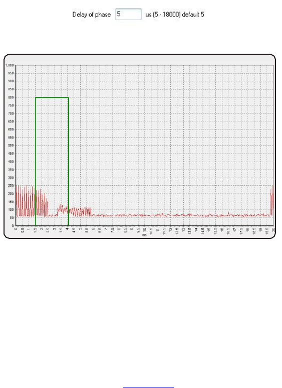
(C) In Synchro choose checkbox “manual” and the “mains frequency”. Go to the “Sync”
window. Choose “Automatic read” and click on “Read array” button. Look if there is some
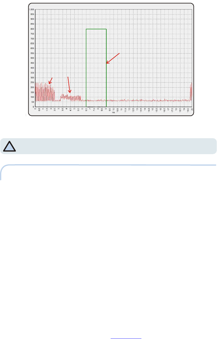
interference with another system that transmit in frequency 8.2 MHz. Set "Delay of
phase" so that signals do not overlap. On Pic. 6 and Pic. 7 you can see two other RF
systems that are synchronized with each other. The farther away the other systems are,
the smaller the pulses will be, but the systems can affect each other up to 100m away in
some cases, resulting in false-alarms and poor detection of all RF systems. The pulses
may be combined
with electrical
noise, so
it
is important to evaluate the signal
closely.
Pic. 5 - Delay of phaze setting in "Sync" window
Pic. 6 - Unsynchronized systems
13
MONO82_USR_MAN_REV_A
This document was created to provide intended recipient documentation of requested device for technician purposes only. Any other usage of this document is an illegal and unlawful act. This document is a confidential and pro prietary
document of Universal Surveillance Systems and consist of i nformation what can be protected by copyrights or the others intellectu al property protection instr um ents of the others subjects. All other information, what are not generally
known ones, is an intellectual property of Universal Surveillance Systems. This document including any and all attachmen ts hereto is intended solely to be used by individual or entity to which it is addressed. If the reader of this
document is not the intended recipient, or an employee or agent responsible for delivering this document to its intended recipient, you are herewith notified that any dissemination, distribution, copying or retention of this document
or the informa tion contained her ein is strictly prohibited. If you have received this document in error, please notify us at service@u nivse ralea s. com immediately and permanen tl y delete or/and destroy the original and any copy or
printout thereof.
your TX pulses
pulses
f
rom
other sys
t
ems
Pic. 7 - Properly synchronized systems
*NOTE: If installing more than one controller unit in the same location, turn on
*
and synchronize
the systems one
by one!!!
7.6 FINAL
(A)
Move
on to the second
electronic
board if
these
will be also installed.
Repeat steps
7.3-
7.5.
(B) Disconnect from the system on the Settings page and then turn OFF the electronic
board (HW:N:6163, REV.8.3;
SW:V3.4).
(C) Drill
holes
and attach the
antennas
to the
floor.
Lay the
cables
in the floor and
place
the
controller unit in its final
location.
(D) Turn the system back on and reconnect. Test detection again with the antennas
attached and cables in the floor. Verify that
everything
is okay and set the Alarm lights and
sounds
to the
customer's
wishes.
(E) On the Settings page, Export the settings to a text file for future reference. Also, a
screenshot of each page in the software can be extremely helpful to have for reference,
even more so than the settings
file.
14
MONO82_USR_MAN_REV_A
This document was created to provide intended recipient documentation of requested device for technician purposes only. Any other usage of this document is an illegal and unlawful act. This document is a confi dential and pr oprietary
document of Universal Surveillance Systems and consist of i nformation what can be protected by copyrights or the others intellectu al property protection instr um ents of the others subjects. All other information, what are not generally
known ones, is an intellectual property of Universal Surveillance Systems. This document including any and all attachmen ts hereto is intended solely to be used by individual or entity to which it is addressed. If the reader of this
document is not the intended recipient, or an employee or agent responsible for delivering this document to its intended recipient, you are herewith notified that any dissemination, distribution, copying or retention of this document
or the informa tion contained her ein is strictly prohibited. If you have received this document in error, please notify us at service@u nivse ralea s. com immedia tely and permanen tl y delete or/and destroy the original and any copy or
printout thereof.
8. DECLARATION
8.1 EQUIPMENT MODIFICATION CAUTION
Equipment changes or modifications not expressly approved by manufacturer, the party
responsible for FCC &/or CE compilance, could void the user's authority to operate the
equipment and could create
a
hazardous
condition.
8.2 FCC COMPLIANCE
This equipment has been tested and found to comply with the limits for Class A
digital device pursuant to Part 15 of the FCC Rules. These limits are designed to
provide reasonable protection against harmful interference when the equipment is
operated in a commercial environment. This equipment generates, uses, and can
radiate radio frequency energy and, if not installed and used in accordance with the
instruction's manual, may cause interference to radio communications. Operation of
this equipment in a residential area is likely to cause interference in which case the
user will be required to correct the interference at his own expense. The user is
cautioned that changes and modifications made to the equipment without approval
of the manufacturer could void the user’s authority to operate this equipment.
16
MON082_USR_MAN
REV_A
This document was created to provide intended recipient documentation of requested device for technician purposes only. Any other usage of this document is an illegal and unlawful act. This document is a confide ntial and pro prietary document of
Universal Surveillance Systems and consist of infor mation what can be protected by copyrights or the others intell ectual property protection instruments of the others subjects. All other informa tion, what are not generally known ones, is an
int ell ec tual property of Universal Surveillance Systems. This document including any and all attachments her eto is intended solely to be used by individual or entity to which it is addressed. If the reader of this document is not the intended
recipient, or an employee or agent responsible for delivering this document to its intended recipient, you are herewith notified that any diss emination, distribution, copying or retention of this document or the information contained herein is
strictly prohibited. If you have received this document in error, please notify us at servi ce@univs er al ea s.com immediately and permanently delete or/and destroy the original and any copy or printout thereof.
<
9. NOTES