Universal Surveillance Systems USS-RF-DEAC-82 8.2 MHz Deactivator User Manual RFDEAC CT7 A5 USR MAN REV A
Universal Surveillance Systems, LLC 8.2 MHz Deactivator RFDEAC CT7 A5 USR MAN REV A
User Manual
RF DEACTIVATOR
USER'S MANUAL
HISTORY OF REVISIONS AND REPAIRS:
01/2014 REV.A (HW:N:09-000-005, REV.4)
RFDEAC_CT7_A5_USR_MAN_REV_A
2
RFDEAC_CT7_A5_USR_MAN_REV_A
USER'S MANUAL
CONTENT
1. Basic information 3
2. Basic device description 3
3. Deactivator parameters and their mutual interactions 4
3.1 Sensing and deactivation 4
3.2 Deactivator operating modes 5
4. Configuration of deactivator's parameters 5
4.1 The usage of one or two deactivators pads 5
4.2 Settings of the deactivation power 6
4.3 Settings of the sensing deactivation power 6
4.4 Settings of the sweeping
frequency
range 6
5. Installation 7
5.1 Faults clearing 7
6. Electronic board description 8
6.1 Terminal description 8
6.2 Jumpers and DIP switch description 9
6.3 Trimmers description 10
6.4 LEDs description 10
7. Declaration 11
7.1 Equipment modification caution 11
7.2 FCC compliance 11

3
USE: The deactivator is determinate for the deactivation the RF sticker labels in
frequency range 8.2 MHz ± 3.625 %. The deactivator can also detect deactivation less
hard
tags
in the
above-mentioned frequency
range.
The deactivator works with all kinds of hard tags and sticker labels in the market for 8.2
MHz
The
synchronization
between
deactivators
and EAS system is the way for the
elimination
of
bad influence between the deactivators and EAS system. This bad influence usually comes
out as
EAS system sensitivity decreasing
or
false
alarms.
2. BASIC DEVICE DESCRIPTION
1.
Embedded 4
LEDs
indicate the
following deactivator
state:
-
The
deactivator
unit is
powered
-
Internal
synchronization
-
LF synchronization led to the deactivator
unit
-
The
detection of sticker
label
or
tag
2.
Maximum deactivation height is
up to 40
cm.
NOTE:
Maximum
output power
of
the
deactivator, 40x40 mm sticker
labels.
*
3.
Maximum detection height is
up to 40
cm.
4. Sound indicator of the detection hard tag or sticker label with possibility of volume
adjustment.
5. The deactivator unit works in only one mode. Detection with deactivation.
1. BASIC INFORMATION
4
3. DEACTIVATOR PARAMETERS AND THEIR MUTUAL INTERACTIONS
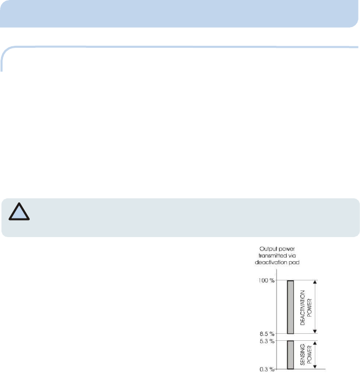
3.1 SENSING AND DEACTIVATING POWER
The
deactivator
needs two output power
levels
for its
operation.
RX Sensitivity Level - Is used for the detection of sticker labels and tags. The bigger this
power is the higher detection height is reached, but the higher the probability is, that the
sticker label is deactivated before its detection. The level of sensing output power (RX) is
found experimentally by reaching acceptable detection height and probability of
successful detection by
mod
ifi
c
a
ti
on
tr
i
mmer RX PWR
tr
i
mmer
.
Th
e
va
lu
e of this
parameter is set at 50
%.
NOTE: All Power settings MUST be left at default settings in USA. USA versions do
*
n o t a l l o w f o r p o w e r a d j u s t m e n t s
Deactivation output power - Is used for deactivation
of sticker labels. This level is set at manufacture. Bad
influence usually comes out as EAS system sensitivity
decreasing or false alarms making. It is necessary to
perform proper synchronization
between EAS system
and the
deactivator.
Pic. 1 - The comparison - possible levels of
‘sensing power’ and ‘deactivation power’
5
3.2 DEACTIVATOR OPERATING MODES
The deactivator unit can o n l y work in 1 mode.
MODE1 - deactivation with detection - The deactivator emits ‘deactivation output power’
pulses, which are defined by TX PWR trimmer. The response after deactivation pulse is
analyzed in order to look for the presence of sticker label or tag inside detection area
(above
or
under deactivation
pad).
4. CONFIGURATION OF DEACTIVATOR'S PARAMETERS
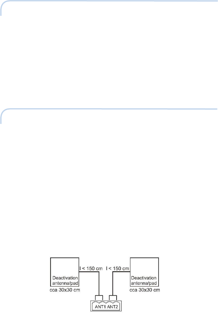
4.1 THE USAGE OF ONE OR TWO DEACTIVATOR PADS
If it is intended the usage of the only one deactivation antenna
(deactivation
pad) it makes
no difference, if it is connected to the terminal ANT1 or ANT2. We recommend keeping
recommended dimensions of
the
deactivation antenna;
it fits
90
% of
installations.
The
usage of two
deactivation antennas/pads can be
requested in some cases.
It can
happen mainly in three following
cases:
1. It is requested to have two deactivation antennas/pads, which are not distant
more than approximately 2-3 m (for example one can be normal deactivation
pad and the
second one
can
be
embedded into bar code
reader).
2. One deactivation antenna/pad is required, but bigger deactivation field is
requested than one
deactivation pad can
give.
Both of deactivation antennas should be connected to terminals ANT1 and ANT2 (for
example first deactivation antenna can be connected to the terminal ANT1 and second
one to the terminal ANT2). Both of antennas will work the same way as per settings of the
operational mode
(MODE1, MODE2, MODE3 or
MODE4).
Pic. 2 - Recommended dimension of deactivation antennas and their connection to the deactivator

6
4.2 SETTINGS OF THE DEACTIVATION POWER
The deactivator deactivation power is determined by settings of the TX PWR trimmer. The
value of this parameter determines the height of the deactivation field. This level should
be chosen the way to assure the reliable sticker labels deactivation. There is general rule
valid, that 50 % level of output power is sufficient for the most sticker labels.
Th
e
va
l
u
e
of this parameter
is set
at 50 %; setting beyond this level is not allowed by the
manufacturer. This setting cannot be changed in USA models.
4.3 SETTINGS OF DEACTIVATION RX SENSITIVITY
The
deactivator
features having the adjustable level of sensing power RX PWR (the power,
what is needed for the detection of the sticker label without its deactivation). The correct
setting of this parameter is very important for the sticker label detection. Too small
sensing output power will give small detection height, but on the
other hand, too
big
output power can deactivate the sticker label without its detection. The correct level of
this
parameter varies
on the sticker label
brand. The value is set 50%. This setting cannot be
changed in USA models
4.4 SETTINGS OF THE STEPPING FREQUENCY RANGE
The
deactivator
is factory set to detect the standard sticker labels. Stepping frequency
range will assure the
detection
of
sticker labels,
which are out of the
standard operational
frequency range of the RF EAS system. Bigger sweeping frequency range will mean less
detection height on the
other hand and vice
versa.
Th
e
va
lu
e of this
parameter
issetat50
% fixed; setting beyond this level is not allowed by the manufacturer and is fixed for
USA models.
8
RFDEAC_CT7_A5_USR_MAN_REV_A
7
5. INSTALLATION
There are several simple and essential rules mentioned, which keeping will assure very
good parameters of
the
deactivation.
• Don’t install deactivation antennas/pads to the near proximity of metal
objects. There should be no metal object under the deactivation antenna/pad
closer than from 3 to 4 cm. There should be no metal object next to the
deactivation antenna/pad closer than from 5
to 10
cm.
• Don’t install the deactivation
antennas/pads
to the close proximity of the other
electronic devices.
• Don’t install wire between the deactivator unit and the deactivation
pad/antenna along with the
others
cables.
• Pay your utmost attention to install deactivators as far as possible from the RF
EAS system. The particular minimum distance depends mainly on the quality of
used RF
EAS
system.
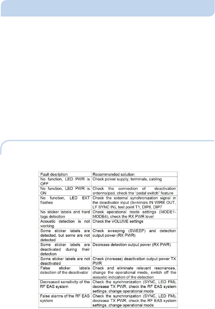
5.1 FAULTS
CLE
ARING
8
RFDEAC_CT7_A5_USR_MAN_REV_A
8
6. ELECTRONIC BOARD DESCRIPTION
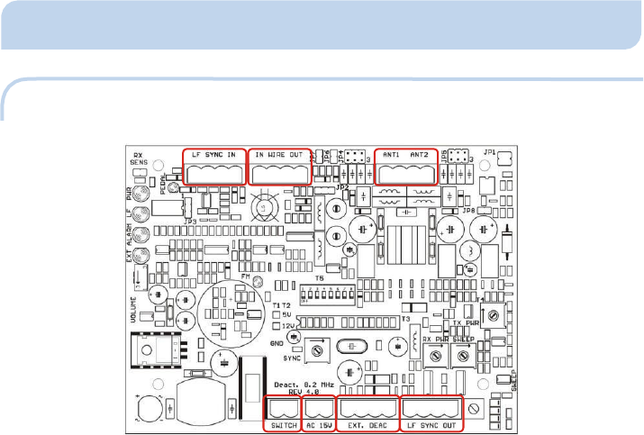
6.1 TERMINAL DESCRIPTION
Pic. 3 - Location of terminals on the board.
SWITCH -
The
deactivator
switch.
AC 15V
-
Power supply terminal
(AC
15V/11VA).
EXT.DEAC -
Reserved for the future
board
expansion.
LF SYNC OUT – Not used in USA
ANT1 ANT2 -
Deactivation antennas
terminal.
IN WIRE OUT – Not used in USA
LF SYNC IN –
Not used in USA
8
RFDEAC_CT7_A5_USR_MAN_REV_A
9
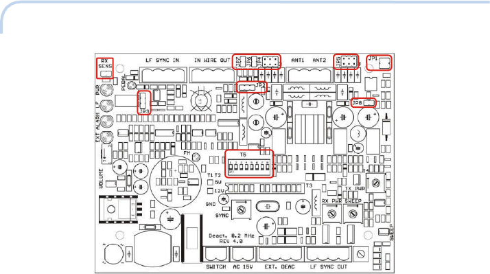
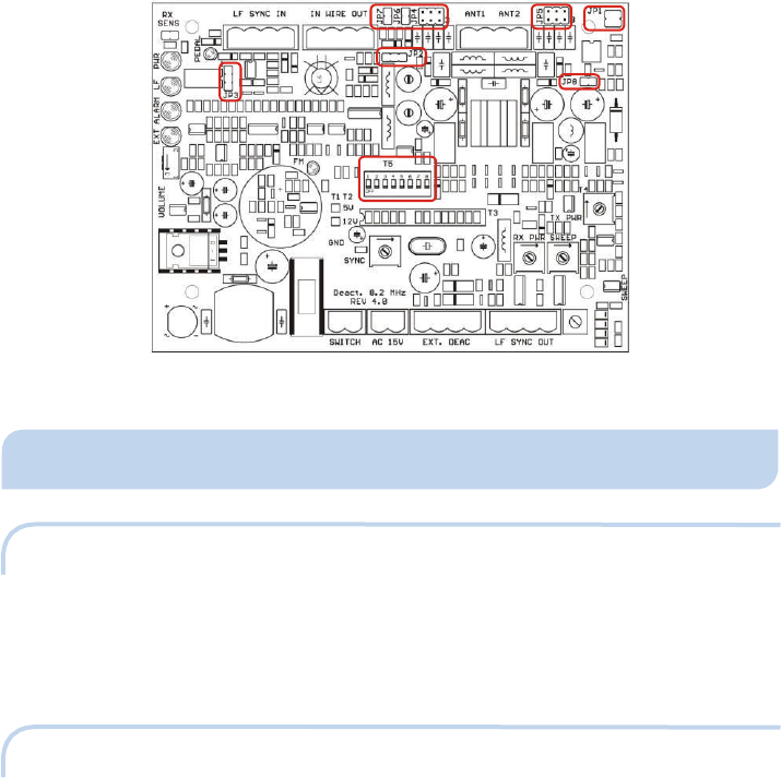
6.2 JUMPERS AND DIP SWITCH DESCRIPTION
Pic. 4 - Location of jimpers and DIPs on the board.
JP1 -
The free place for spare
jumpers.
JP2 -
Source
of
high frequency
synchronization.
JP3 - Delay between received trigger signal and the transmitted one – in mode of low
frequency
mode.(Not USED IN USA MODEL)
JP4, JP5 - In order to be able to put antenna on resonance, the effects of loop geometries
and different cable lengths can be composed to certain degree. By jumpers JP4, JP5 can
be
done
the matching
deactivation antenna to deactivator
unit.
JP6, JP7 - Terminating resistors to the high frequency input terminal IN WIRE. These
resistors should
connected
to this terminal if there is nothing connected to the (WIRE OUT
terminal).
JP8 -
Reserved for the future
usage
–
the expansion deactivator
unit.
RX SENS -
The sensitivity of the deactivator receiver. Higher
receiver sensitivity
brings
higher detection
height.
DIP
1,2
-
Deactivator
operational
modes.
DIP 3
-
Way of
deactivator
synchronization. (NOT USED IN USA MODEL LEAVE IN OFF MODE)
DIP 4, DIP 5 - Time between particular deactivation pulses in the internal synchronization
mode.
DIP 6 -
The feature „pedal“ is
enabled/disabled.
DIP 7
-
Way of the
synchronization.
DIP 8 -
Sensitivity of
the hard tags
and
sticker labels
recognition.
8
RFDEAC_CT7_A5_USR_MAN_REV_A
10
6.3 TRIMMERS DESCRIPTION
Pic. 5 - Location of trimmers on the board.
TX PWR -
Deactivation output power
(set at 50%).
RX PWR -
Sensing
output power
(set at
50%).
Stepping - The range of sweeping is set from the production fixed at 50%.
SYNC - The time between the request for deactivation and transmission of
detection/deactivation pulse and the settings of deactivation output power TX PWR and
RX PWR) The purpose of trimmer is to put the detection/deactivation pulse into time,
where the EAS system doesn’t analyze the tag and sticker label response
and therefore
it
is resistant to deactivator transmissions
(time multiplex
principle). VOLUME
-
The volume of
buzzer
–
the
indication of the
hard tag
or
sticker label
detection.
6.4 LEDS DESCRIPTION
PWR -
Power
supply
LED.
LF
-
Signal on low frequency synchronization terminal LF SYNC
IN.
EXT -
Indication of the
internal
synchronization.
ALARM -
Alarm
LED.
PEDAL -
Pedal switch
LED.
FM - The indicator, if currently received and FM demodulated signal is good enough
for
proper external
synchronization.
8
RFDEAC_CT7_A5_USR_MAN_REV_A
11
Pic. 6 - Location of LEDs on the board.
7. DE
CL
ARATION
7.1 EQUIPMENT MODIFICATION CAUTION
Equipment changes or modifications not expressly approved by manufacturer, the party
responsible for FCC &/or CE compliance, could void the user's authority to operate the
equipment and could create
a
hazardous
condition.
7.2 FCC COMPLIANCE
“This equipment has been tested and found to comply with the limits for Class A
digital device pursuant to Part 15 of the FCC Rules. These limits are designed to
provide reasonable protection against harmful interference when the equipment
is operated in a commercial environment. This equipment generates, uses, and
can radiate radio frequency energy and, if not installed and used in accordance
with the instruction's manual, may cause interference to radio communications.
Operation of this equipment in a residential area is likely to cause interference in
which case the user will be required to correct the interference at his own
expense. The user is cautioned that changes and modifications made to the
equipment without approval of the manufacturer could void the user’s authority
to operate this equipment.”