Uniwill Computer 3945ABGXPCIA Shuttle XPC (Wireless 802.11a+b+g) User Manual 1602896
Uniwill Computer Corp. Shuttle XPC (Wireless 802.11a+b+g) 1602896
UserManual.wiki
>
Uniwill Computer
>
3945ABGXPCIA User Manual
Users Manual
Navigation menu
Upload a User Manual
Namespaces
Wiki Guide
HTML
PDF
Info
Views
User Manual
Discussion / Help
Navigation

![chapter 1 getting to know the basics1-4Package ContentPlease take a moment to make sure you have the following content in the box.[ Proposal: Will take a live black and white picture of the actual items.]](https://usermanual.wiki/Uniwill-Computer/3945ABGXPCIA/User-Guide-663094-Page-4.png)
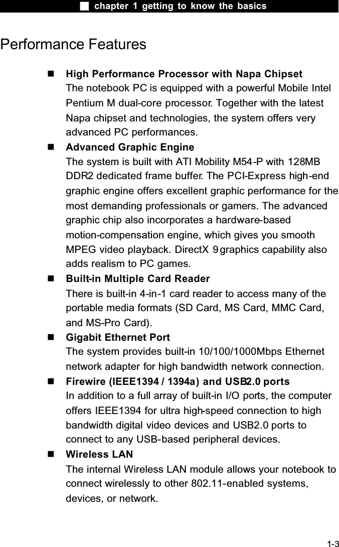
![chapter 1 getting to know the basics1-5System At A GlanceFront ViewWarning: Do not place any heavy objects on the top of computer. This may damage the unit1. Power / Suspend ButtonThe power/suspend button turns the computer on and off and it also acts as a system suspend key. Press momentarily to turn on the system. Press and hold for at least 4 seconds to turn off the system. How this key behaves can be defined in [Start > Settings > Control Panel > Power Options > Advanced] menu. Press the power / suspend button again to return from the suspend mode. (See Chapter 3 for more details on system suspend function.)2. 4-in-1 Card ReaderThe 4-in-1 Card Reader supports SD Card, MS Card, MMC Card, and MS-Pro Card.3. USB2.0 Port (x1) The Universal Serial Bus (USB2.0-compliant) port allows you to](https://usermanual.wiki/Uniwill-Computer/3945ABGXPCIA/User-Guide-663094-Page-5.png)


![chapter 1 getting to know the basics1-21EthernetYour computer is equipped with a 10/100/1000Base-TX FastEthernet network adapter. Connect the active LAN cable to the RJ-45 LAN port located on the left side of the computer. This allows you to access and transmit data in the local area network. Connecting to the NetworkUse Unshielded Twisted Pair (UTP) Ethernet cable only.1. Insert one end of the UTP cable into the network connector until the connector snaps securely into the receptacle. 2. Either connect the other end of the cable to an RJ-45 jack wall outlet or to an RJ-45 port on a UTP concentrator or hub in the network. Cabling Restriction for NetworksThe following restrictions should be observed for 10/100/1000BASE-TX networks:The maximum cable run length is 100 meters(m) (328 feet[ft]). For 100Mbps or 1000Mbps operations, use Category 5 wiring and connections.Note: Consult Windows manual and / or Novell Netware user’s guide for the software installation, configuration, operation of the network.](https://usermanual.wiki/Uniwill-Computer/3945ABGXPCIA/User-Guide-663094-Page-21.png)
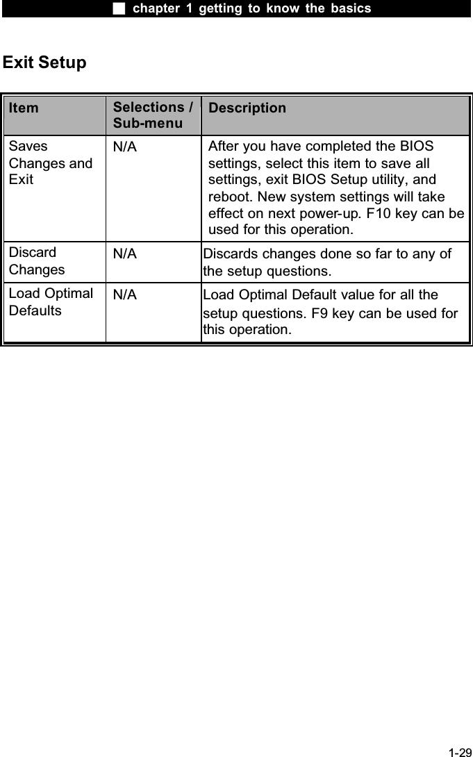
![chapter 1 getting to know the basics1-28Power SetupItem Selections /Sub-menuDescriptionLong Battery Life ModeEnableDisableWhen Enabled, maximum battery life can be achieved. The processor performance is lowered.Power Button ModeOn/OffSuspend[On/Off]: When the power button is pressed, the system is turned off.[Suspend]: When the power button is pressed, the system enters the suspend mode. !Note: The Suspend Mode selection in BIOS only applies to older Windows version (such as Windows 3.1 or Windows 95 or NT4) or non-Windows operating system. In Windows ME / 98SE / 2000 / XP, suspend mode and settings are determined by settings in the Power Options Properties (Start > Control Panel > Power Options).](https://usermanual.wiki/Uniwill-Computer/3945ABGXPCIA/User-Guide-663094-Page-28.png)
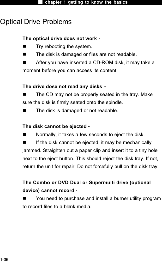
![chapter 1 getting to know the basics1-33Audio ProblemsNo speaker output - Software volume control is turned down in Microsoft Sound System or is muted. Double-click the speaker icon on the lower right corner of the taskbar to see if the speaker has been muted or turned down all the way. Most audio problems are software-related. If your computer worked before, chances are software may have been set incorrectly. Go to [Start > Settings > Control Panel] and double-clickthe Sounds and Audio Devices icon. In the Audio page, make sure that Realtek HD Audio is the default playback device.Sound cannot be recorded - You will need to plug-in an external microphone to the microphone connector to record sound. Double-click the speaker icon on the lower right corner of the taskbar to see if the microphone has been muted.1. Click Options and select Properties.2. Select Recording and click the OK button.3. After Click OK button, the recording volume control panel will appear. Go to [Start > Settings > Control Panel] and double-clickthe Multimedia icon (or Sounds and Audio Devices icon). In the Volume or Audio page, make sure that Realtek HD Audio is the default recording device.](https://usermanual.wiki/Uniwill-Computer/3945ABGXPCIA/User-Guide-663094-Page-33.png)
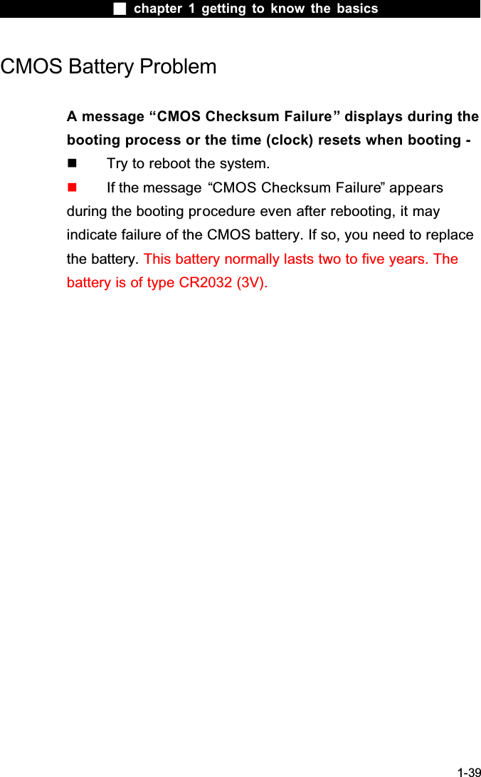
![chapter 1 getting to know the basics1-34Hard Disk ProblemsThe hard disk drive does not work or is not recognizable - If you had just performed a hard disk upgrade, make sure the hard drive connector is not loose and the hard disk drive is also correctly seated. Remove it and reinsert it firmly, and restart your PC. (Refer to Chapter 4 for details.) The new HDD may need to be partitioned and reformatted. O/S and drivers will need to be re-installed as well. Check the hard disk indicator LED. When you access a file, the LED lamp should light up momentarily. The new HDD may be defective or is not compatible. If your computer has been subjected to static electricity or physical shock, you may have damaged the disk drive.The hard drive is making abnormal whining noises - You should back up your files as soon as possible. Make sure the source of noise is indeed from the hard drive and not the fan or other devices.The hard disk drive has reached its capacity - Run Disk Cleanup utility in Windows. [Start > All Programs> Accessories > System Tools > Disk Cleanup] The system will prompt you for what to do. Archive files or programs that you had no longer used by moving them to an alternative storage medium (floppy disk, optical record-able disk, etc.) or uninstall programs that no longer use. Many browsers store files in the hard drive as a cache to speed up the performance. Check the program’s Online Help](https://usermanual.wiki/Uniwill-Computer/3945ABGXPCIA/User-Guide-663094-Page-34.png)
![chapter 1 getting to know the basics1-35for instructions on decreasing the cache size or on removing temporary Internet files. Empty the Recycle Bin to create more disk space. When you delete files, Windows saves them to the Recycle Bin.The hard disk takes longer to read a file - If you have been using the drive for a period, the files may be fragmented. Go to [Start > Programs > Accessories > System Tools > Disk Defragmenter] to perform a disk defragmentation. This operation may take a while. Interrupt requests or problems with other hardware devices may have occupied the CPU and therefore slows down the system performance.The files are corrupted - Run the Error-checking utility in Windows to check the HDD. Double-click My Computer. Right-click C: and select Properties. Click Check Now in Error-checking in Tools.](https://usermanual.wiki/Uniwill-Computer/3945ABGXPCIA/User-Guide-663094-Page-35.png)
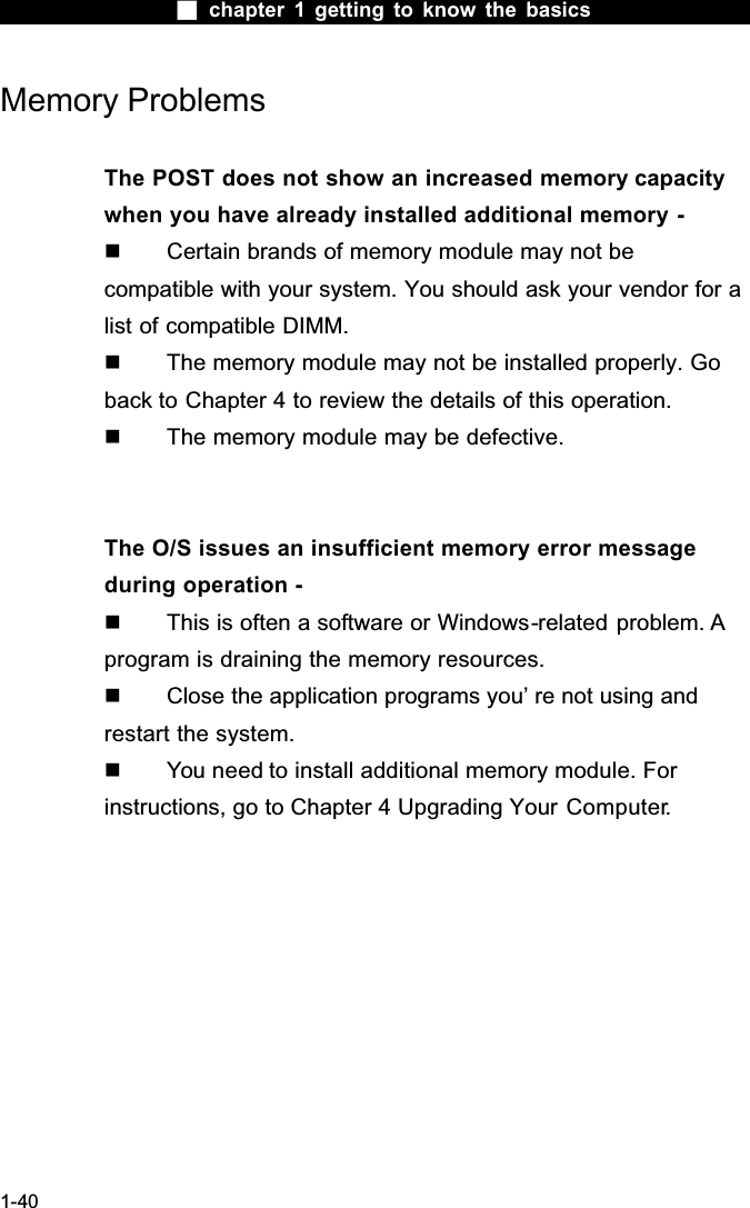
![chapter 1 getting to know the basics1-37Display ProblemsThe display panel is blank when the system is turned on - Make sure the computer is not in the Standby or Hibernate suspend modes. The display is turned off to conserve energy in these modes.The screen is difficult to read - The display resolution should at least be set to atleast1024x768 for optimal viewing.1. Go to [Start > Settings > Control Panel] and double-clickthe Display icon. 2. Under the Settings page, set screen resolution to at least 1024x768 and choose at least 256 colors.The screen flickers - It is normal if the display flickers a few times during shutting down or powering up.](https://usermanual.wiki/Uniwill-Computer/3945ABGXPCIA/User-Guide-663094-Page-37.png)
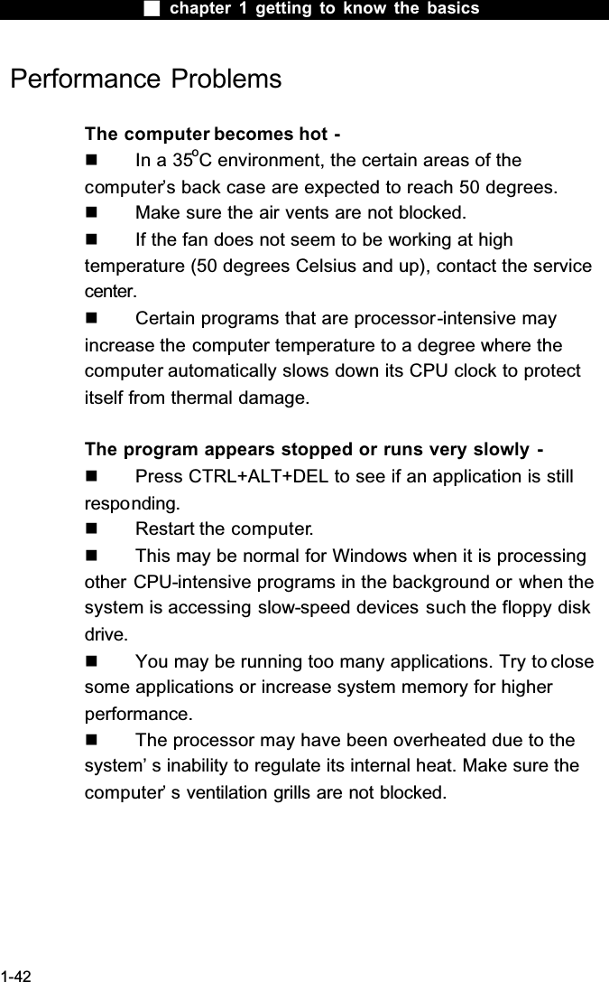
![chapter 1 getting to know the basics1-38Keyboard and Mouse Problems The built-in touch pad performs erratically - Make sure there is no excess perspiration or humidity on your hand when using the touch pad. Keep the surface of the touch pad clean and dry. Do not rest your palm or wrist on the surface of the touch pad while typing or using the touch pad.The built-in keyboard accepts no input - If you are connecting an external keyboard to the system, the built-in keyboard may not work. Try restarting the system.The characters on the screen repeat while I type. You may be holding the keys down too long while you’ re typing. Keep the keyboard clean. Dust and dirt under the keyscould cause them to stick. Configure the keyboard to wait longer before the auto repeat feature starts. To adjust this feature, Go to [Start > Settings > Control Panel], and double-click the Keyboard icon. A dialogue box shows up with the adjustable settings for the keyboard.](https://usermanual.wiki/Uniwill-Computer/3945ABGXPCIA/User-Guide-663094-Page-38.png)
![chapter 1 getting to know the basics1-41Network Adapter / Ethernet ProblemsThe Ethernet adapter does not work - Go to [Start > Settings > Control Panel > System > Hardware > Device Manager]. Double-click on Network Adapters and check if Realtek RTL8169/8110 Family Gigabit Ethernet NIC appears as one of the adapters. If it does not exist, Windows has not detected the Realtek RTL8169/8110 Family Gigabit Ethernet NIC or the device driver has not been installed properly. If there is a yellow mark or red-cross on the network adapter, it may be a device or resource conflict. Replace or update the device driver from the factory CD-ROMdisk or consult Windows manual on how to solve the resource conflict problem. Make sure the physical connections on both ends of the cable are good. The hub or concentrator may not be working properly. Check to see if other workstations connected to the same hub or concentrator is working.The Ethernet adapter does not appear to operate in the 1000Mbps transmission mode - Make sure the hub you are using supports 1000Mbpsoperation. Make sure that your RJ-45 cable meets the 1000Base-TX requirements. Make sure the Ethernet cable is connected to the hub ̆socket that supports 1000Base-TX mode. The hub may have both 100Base-TX and 1000Base-T sockets.](https://usermanual.wiki/Uniwill-Computer/3945ABGXPCIA/User-Guide-663094-Page-41.png)
![chapter 1 getting to know the basics1-43Firewire (IEEE1394) and USB2.0 ProblemsThe USB device does not work - Windows NT 4.0 does not support USB protocols Check the settings in the Windows Control Panel. Make sure you have installed the necessary device drivers. Contact the device vendor for additional support.The IEEE1394 port does not work - Go to [Start > Settings > Control Panel > System > Hardware > Device Manager]. You should see an entry which reads “Texas Instrument OHCI Compliant IEEE 1394 Host Controllers” . If it does not exist, Windows has not detected the host controller or the device driver has not been installed properly. If there is a yellow mark or red-cross on the 1394 host controller, it may be a device or resource conflict. Replace or update the device driver from the factory CD-ROM disk orconsult Windows manual on how to solve the resource conflictproblem. Make sure the cable is fully connected. Make sure you have installed the necessary device drivers. Contact the device vendor for additional support.](https://usermanual.wiki/Uniwill-Computer/3945ABGXPCIA/User-Guide-663094-Page-43.png)


![chapter 1 getting to know the basics1-59PrefaceUsing This ManualThis User’ s Manual contains general information about thehardware and software setup, troubleshooting, and technical specifications of the XPC computer.Symbols and ConventionsThe following conventions and symbols are used in this manual: When keys are to be pressed at the same time, a plus (+) symbol is used. For instance, Fn+F7 means holding Fn and F7 keys at the same time. When a series of clicking actions is needed in Windows O/S, [ ] and > symbols are used. For instance, [Start > Settings > Control Panel > Display] means clicking the Start icon first, then the Settings, then the Control Panel, then the Displayicon. When you need to make a selection with the touch pad (or mouse), you will be asked to ’ select’ or ‘ click’ or ‘ double-click’,‘right-click’ the item.Note: Text in this format and symbol means specific instructions, commentary, sidelights, or any additional information or notes that you should be aware of.Warning: Text in this format and symbol means that failures to comply with the given instructions or information could result in damage to your computer or could cause bodily harm or loss of life.](https://usermanual.wiki/Uniwill-Computer/3945ABGXPCIA/User-Guide-663094-Page-59.png)