Utel UT-2006 Audio and Video Transmitter User Manual Manual
Utel Co. Ltd. Audio and Video Transmitter Manual
Utel >
Manual
TIU - 200A
Before operating the system,
please read this manual thoroughly
and keep it for future reference.
2.4GHz
2.4GHz WIRELESS TRANSMITTER
& WIRELESS RECEIVER
N6YUT-2006

UTEL CO.,LTD
TIU-200A
THIS DEVICE COMPLIES WITH PART 15 OF THE FCC RULES.
OPERATION IS SUBJECT TO THE FOLLOWING TWO CONDITIONS:
(1) THIS DEVICE MAY NOT CAUSE
HARMFUL INTERFERENCE, AND
(2) THIS DEVICE MUST ACCEPT ANY
INTERFERENCE RECEIVED,
INCLUDING INTERFERENCE THAT MAY
CAUSE UNDESIRED OPERATION.
Caution: Any changes or modifications in
construction of this device which are not
expressly approved by the party responsible
for compliance could void the users
authority to operate the equipment.
CONTENTS
1. SUB - ASSY'S IN THIS UNIT - - - - - - - - - - - - - - - - - - - - - 1
2. CONTROLS AND FUNCTIONS - - - - - - - - - - - - - - - - - - - - - - - 2

3. INSTALLATION - - - - - - - - - - - - - - - - - - - - - - - - - - - 4
3-1. INSTALLATION OF WIRELESS TRANSMITTER - - - - - - - - - - - - 6
3-2. INSTALLATION OF WIRELESS RECEIVER - - - - - - - - - - - - - - 14
4. MULTIPLE CHANNEL OPERATION - - - - - - - - - - - - - - - - - - - - 19
5. TROUBLESHOOTING - - - - - - - - - - - - - - - - - - - - - - - - - 23
6. SPECIFICATIONS - - - - - - - - - - - - - - - - - - - - - - - - - 24
SUB - ASSY'S IN THIS UNIT
Standard package TIU-200A
1- Transmitter
1- UL Approved AC adaptor
1- RCA A/V cable
1- User's manual
RIU-100AN / 100AP
1- Receiver
1- UL approved AC adaptor
1- RCA A/V cable
1- RF cable
Optional Items Extra wireless transmitter
(Not included) Extra wireless receiver
CCD Video Camera
Extra RCA A/V cable
Extra RF cable
Warranty registration card
CHECK LIST PRIOR TO USE
CHECK THESE INSTRUCTIONS BELOW BEFORE OPERATING THIS UNIT.
1. Keep distance at least 10 feet between the transmitter and receiver when you
install it because high frequency radio waves of 2.4GHz may cause an interfering
problem between channels, which is the reason of the distorted picture on the monitor.
2. Turn and adjust the antenna of the transmitter and receiver in order to optimize
the picture condition. Be aware that maximum scope of turning the antenna is 90°
towards right and left. Therefore, Do not turn it over 90°to prevent breakage.
3. Be sure to adjust the adaptor correctly to the exact power (120V or 220V you are
using) before installation.
FOR EFFICIENT USE
1. External radio waves may cause an interfering problem and geographical features
may affect the communication distance.
2. Keep in mind the usage of instructions for effective maintenance of your camera.
CONTROLS AND FUNCTIONS
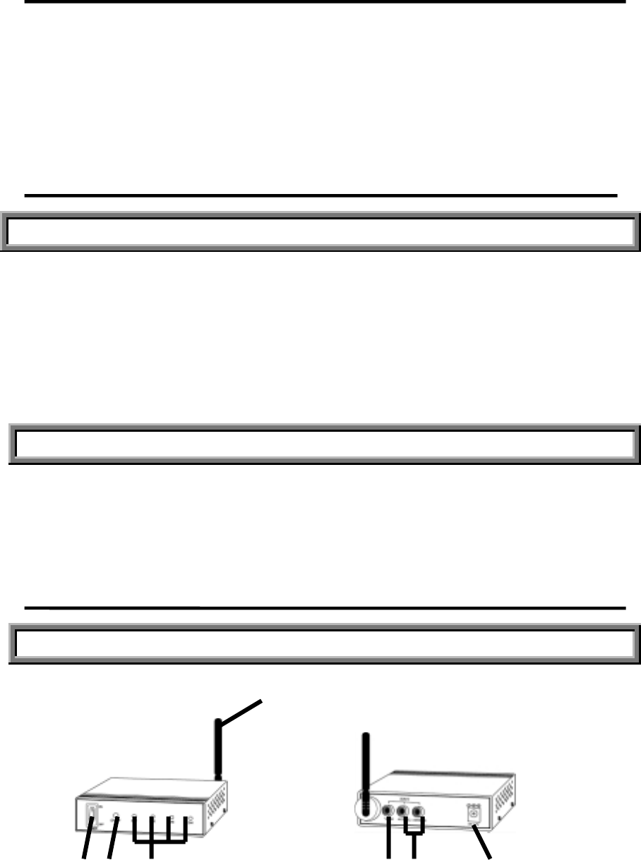
WIRELESS TRANSMITTER
FRONT VIEW REAR VIEW
1
2 3 4 5 6 7
1. 2.4GHz A/V ANTENNA
The high gain directional dipole antenna sends the A/V modulated RF signal to the
receiver.
2. POWER SWITCH
Controls power on/off. Be sure to set the switch to "OFF" before plugging the
AC adaptor into the unit and AC outlet.
3. CHANNEL SELECTOR
Push button switch for channel selection
4. LED CHANNEL INDICATORS
Indicators of selected channel
5. VIDEO INPUT JACK (Yellow)
RCA jack for video input source connection
6. AUDIO INPUT JACKS (Left : White, Right : Red)
RCA L/R jacks for Audio input source connection
7. DC IN JACK
Connect the supplied 12V 500mA AC adaptor
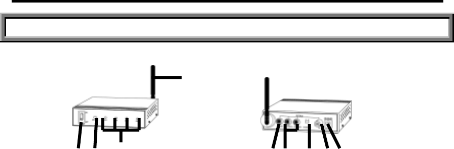
CONTROLS AND FUNCTIONS
WIRELESS RECEIVER
FRONT VIEW REAR VIEW
2 3 4 5 6 7 8 9
1. 2.4GHz A/V ANTENNA
The high gain directional dipole antenna receives the RF signal.
2. POWER SWITCH
Controls power on/off. Be sure to set the switch to "OFF" before plugging the
AC adaptor into the unit and AC outlet.
3. CHANNEL SELECTOR
Push button switch for channel selection
4. LED CHANNEL INDICATORS
Indicators of selected channel
1
5. VIDEO OUTPUT JACK (Yellow)
RCA jack for video output
6. AUDIO OUTPUT JACK (Left : White, Right: Red)
RCA L/R jacks for Audio output
7. RF CHANNEL SELECTOR
Channel 3,4 selector to operate with TV(NTSC Standard)
8. RF OUTPUT CONNECTOR
Connector for TV connection
9. DC IN JACK
Power supply for 12V 500mA AC adaptor
INSTALLATION
WIRELESS TRANSMITTER
DC 12V 500mA
AC ADAPTOR
Transmitting From
1. Place the wireless transmitter on or near the A/V source unit.
2. Connect the 500mA AC adaptor to the DC IN jack on the receiver and plug it
into the 120V AC outlet.
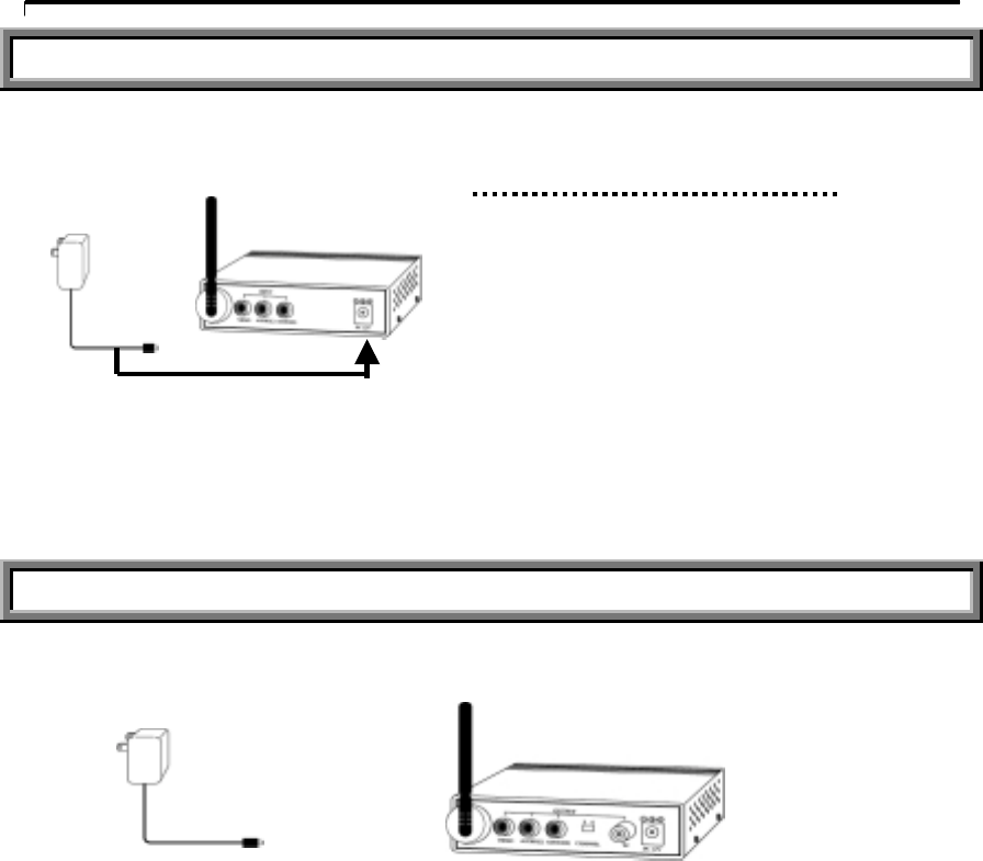
WIRELESS RECEIVER
DC 12V 500mA
AC ADAPTOR
.Satellite Receiver .Camcorde
r
.Cable TV .Surveillance Camera
.VCR .Computer
.Laser Disc Player (convertible card required)
.Wireless Cable .A/V Receiver
.Digital Video Disc .CD Player
Connects to
·TV
·Monitor
·Computer (convertible card required )
·Speakers
1. Place the wireless receiver on or near the TV, monitor or other A/V unit.
2. Connect the 500mA AC adaptor to the DC IN jack on the receiver and plug it
into the 120V AC outlet.
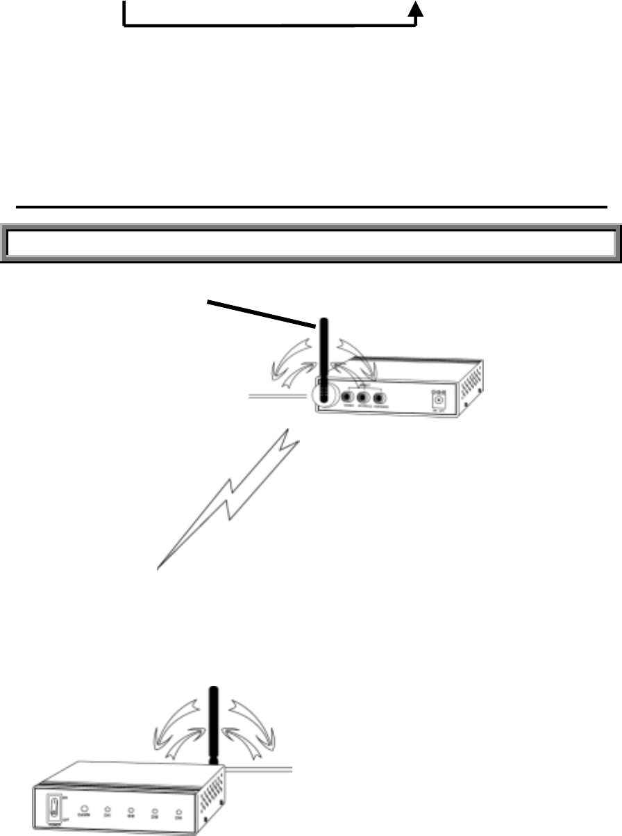
INSTALLATION
ADJUSTING ANTENNA OF UNIT
RF ANTENNA
WARNING!
Please do not turn the antenna towards
the same way more than 90 degrees.
TRANSMITTER
IMPORTANT NOTE FOR CHANNEL SELECTION
Search the CH 1-CH 4 and select the best one for optimum reception in
your area. Both transmitter and receiver must be set to the same channel.
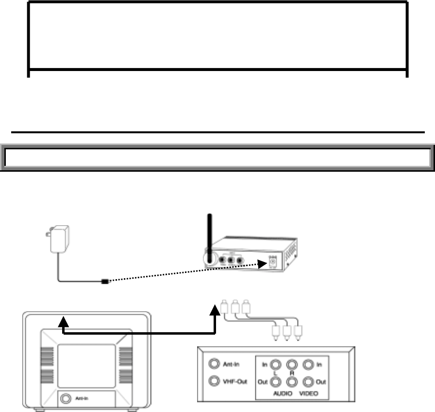
INSTALLATION OF WIRELESS TRANSMITTER
THE MAXIMUM RANGE IS 300 FT WITHOUT LOSS OF ANY PICTURE / SOUND QUALITY
12V 500mA
AC Adaptor TRANSMITTER
RCA cable(Optional)
Rear OF VCR
Rear of TV RF Cable
Note: Be sure to set the power on the transmitter to "OFF" before following steps
below.
1. Connect one end (triple plugs) of the RCA cable to the A/V jacks on the transmitter,
and the other end to the Audio/Video Out jacks on your VCR.
Be sure to match the color of the plugs in both connection.
If your VCR has only one audio out jack (mono sound), connect the white
plug(Audio-L) to your VCR.
2. If you want to use the system with a nearby TV, connect one end of the supplied
RF cable to the VHF Out jack on your VCR, and the other end to the antenna In
jack on your TV.
3. To receive cable transmission on your TV without the cable converting box, connect
the cable TV input source to the VHF In jack on your VCR.
4. Turn on the transmitter and search the channel 1-4 by pressing the Channel selector,
and then select the best one for optimum reception in your area.
5. Adjust the antenna direction as necessary.
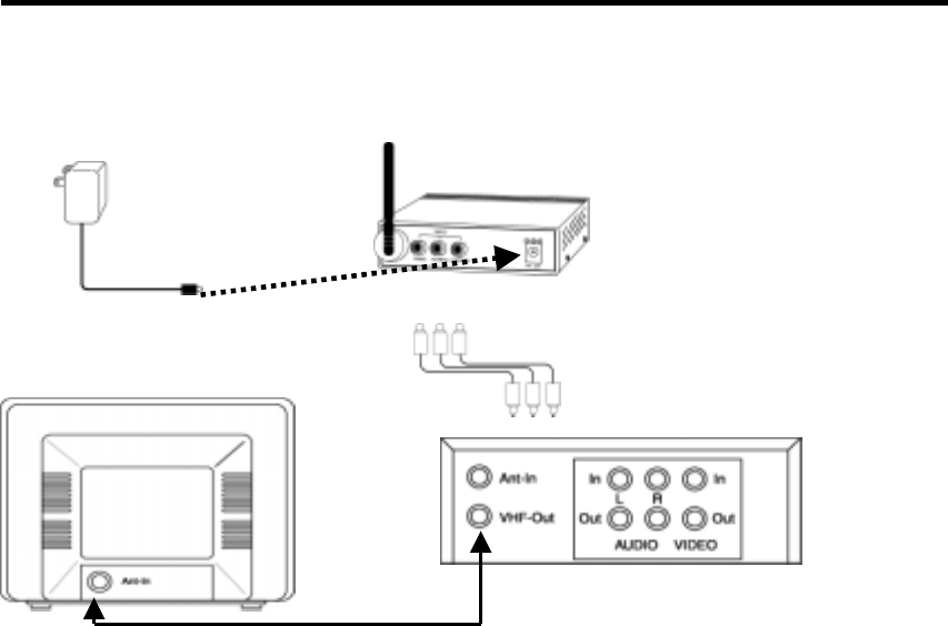
INSTALLATION OF WIRELESS TRANSMITTER
12V 500mA
AC Adaptor TRANSMITTER
RCA cable
Rear OF the Cable Converting Box
Rear of TV RF Cable
Note: Be sure to set the power on the transmitter to "OFF" before proceeding as
follows.
1. Connect one end of the RCA cable to the A/V jacks on the transmitter, and the
other end to the A/V Out jacks on your cable converting box.
Be sure to match the color of the plugs in both connection.
If your cable converting box has only one audio OUT jack, connect the white plug
to your cable converting box.
2. For viewing cable signals through the nearby TV, connect the RF cable to the
Antenna Out jack on your converting box and the Antenna In jack on your TV.
3. Turn on the transmitter and search the channel 1-4 by pressing the Channel Selector,
and select the best one for optimum reception in your area.
Note: Both transmitter and Receiver units must be set to the same channel.
4. Adjust the antenna direction as necessary.
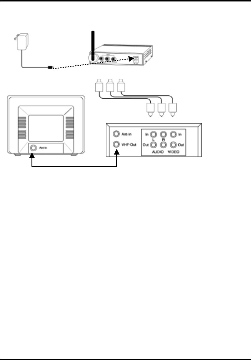
INSTALLATION OF WIRELESS TRANSMITTER
12V 500mA
AC Adaptor TRANSMITTER
RCA cable
Rear of the Satellite Receiver
Rear of the TV RF Cable (or Laser Disc Player)
Note: Be sure to set the Power Switch on the transmitter to "OFF" before following
steps below.
1. Connect one end of the RCA cable to the A/V jacks on the transmitter, and the other
end to the Audio/Video Out jacks on your satellite receiver or laser disc player.
Be sure to match the color of the plugs in both connection.
2. Connect the RF cable to the Antenna Out jack on the satellite receiver (or laser disc
player) and the Antenna In jack on your TV.
3. Turn on the transmitter and search the channel 1-4 by pressing the Channel Selector,
and select the best one for optimum reception in your area.
Note: Both transmitter and receiver units must be set to the same channel.
4. Adjust the antenna direction as necessary.
INSTALLATION OF WIRELESS TRANSMITTER
TRANSMITTING AUDIO/VIDEO FROM CAMCORDER
The system can be used with any camcorder as a wireless monitoring system.
DC 12V 500mA
AC Adaptor
DC IN jack
Camcorder
Video
Audio-L Audio-R
Note: Be sure to set the Power Switch on the transmitter to "OFF" before following
steps below.
1. Place your camcorder near the object you want to monitor such as a sleeping baby,
the playing children, the elderly, or the disabled.
2. Connect one end(triple plugs) of the RCA cable to the A/V jacks on the transmitter,
and the other end to the A/V Out jacks on your camcorder.
Be sure to match the color of the plugs in both connection.
If your camcorder has only one Audio Out jack (mono sound), connect the white
plug(Audio-L) to the single audio out jack on your camcorder.
Note: Some camcorders require the adaptor patch cable.
3. Turn on the transmitter and search the channel 1-4 by pressing the Channel selector,
and select the best one for optimum reception in your area.
Note: Both transmitter and receiver units must be set to the same channel.
4. Adjust the antenna direction as necessary.
INSTALLATION OF WIRELESS TRANSMITTER
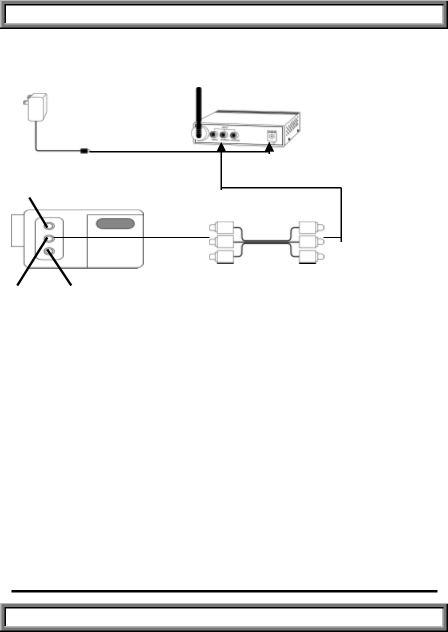
TRANSMITTING AUDIO/VIDEO FROM CCD VIDEO CAMERA
The system can be used with the CCD Video Camera (optional-see order from) as a
RCA Cable
wireless monitoring system for your home or business security.
Rear of the Camera TRANSMITTER
DC IN jack
12V 500mA
AC Adaptor
Note: Be sure to set the Power Switch on the transmitter to"OFF" before following steps below.
1. Place optional CCD camera near the object you want to monitor such as a sleeping baby, the playing
children, the olderly, or the disabled.
2. Connect one end of the RCA cable to the Audio(L)/Video jacks on the transmitter,
and the other end to the A/V Out jacks on the camera cable assembly on the optional
camera. Be sure to match the color of the plugs in both connection.
3. Turn the transmitter on and Search the channel 1-4 by pressing the Channel Selector
on the transmitter, and select the best one for optimum reception in your area.
Note: Both transmitter and receiver units must be set to the same channel.
4. Adjust the antenna direction as necessary.
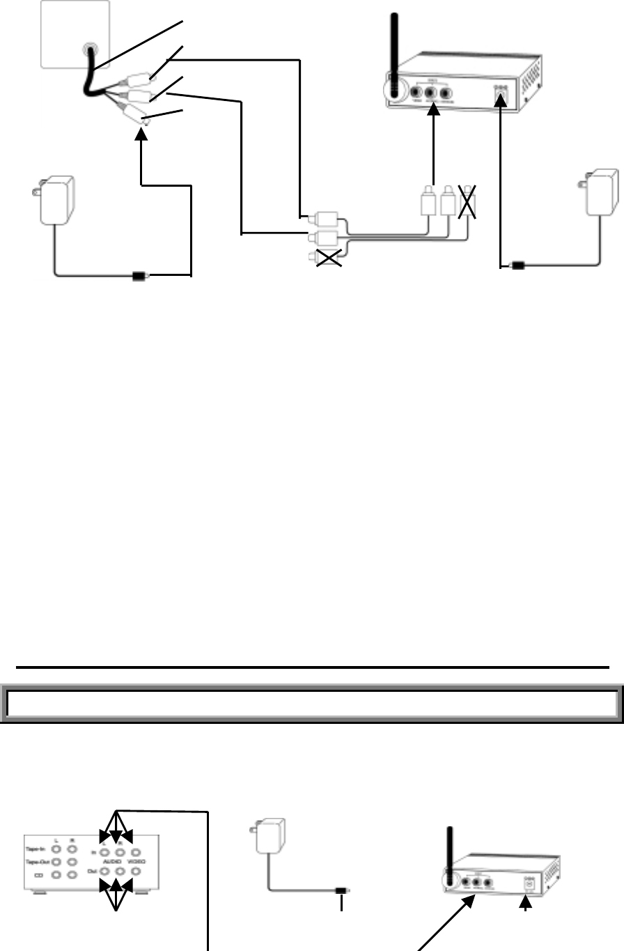
INSTALLATION OF WIRELESS TRANSMITTER
TRANSMITTING AUDIO/VIDEO FROM CCD VIDEO CAMERA
You can transmit signals from several A/V sources to a remote location by using the wireless transmitter
with A/V receivers that have multiple input and output jacks.
Rear of the A/V Receiver 12V 500mA AC Adaptor TRANSMITTER
Camera Cable Assembly
Video Out (Yellow)
Audio Out(White)
DC In
12V 500mA
AC Adaptor
(Optional) Audio
(
R
)
DC IN Jack
RCA Cable(3) (optional)
Rear of the CD Player RCA Cable(1)(optional) Rear of the VCR
Note: Be sure to set the Power Switch on the transmitter to "OFF" before proceeding
as follows.
1. Connect one end of the RCA cable (1) to the A/V Out jacks on any source units you
want to use, and the other end to the A/V In jacks on your A/V receiver.
Be sure to match the color of the plugs in both connection.
2. Connect one end of the RCA cable(2) to the A/V jacks on the transmitter, and the
other end to the Audio/Video Out jacks on your A/V receiver.
3. If you also want to connect your CD player to the system, connect one end of the
RCA cable (3-optional) to the Line-Out (L/R) jacks on your CD player and the other
end to the CD (L/R) jacks on your A/V receiver.
4. Turn on the transmitter and search the channel 1-4 by pressing the Channel Selector,
and select the best one for optimum reception in your area.
Note: Both transmitter and receiver units must be set to the same channel.
5. Adjust the antenna direction as necessary.
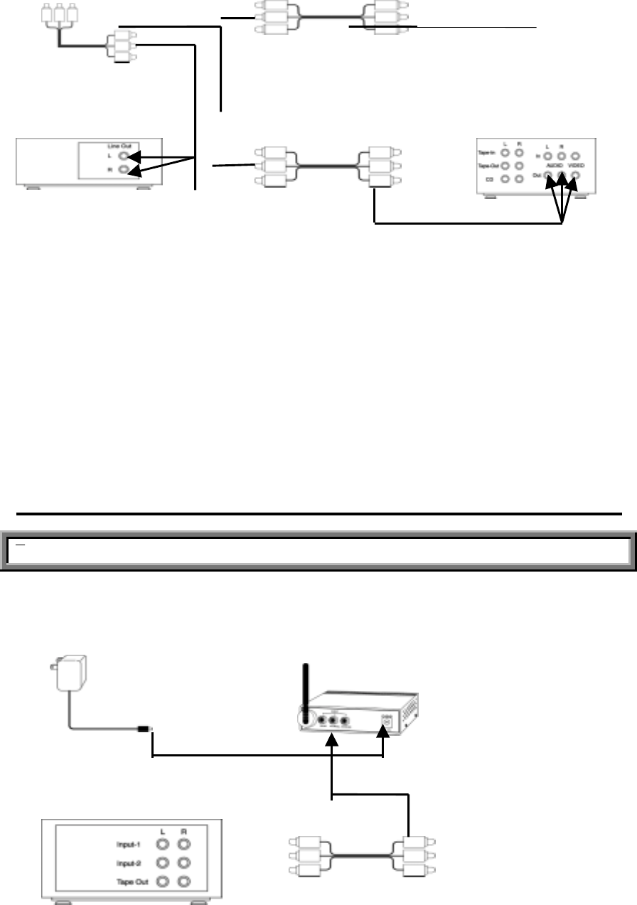
INSTALLATION OF WIRELESS TRANSMITTER
TRANSMITTING SOUND FROM STEREO RECEIVER
You can transmit the sound from your CD player, cassette deck, or radio to your speakers by using the
wireless transmitter.
12V 500mA AC Adaptor TRANSMITTER
DC IN jack
Rear of the Stereo Receiver
RCA Cable
(
2
)
RCA Cable
Note: Be sure to set the Power Switch on the transmitter to "OFF" before processing
following steps.
1. Connect the RCA cable to the Audio (L/R) jacks on your transmitter and the Tape
Out(L/R) jack on your stereo receiver. (Connect to Line-Out jacks, In case of
the cassette deck or CD player)
2. Turn on the transmitter and select the channel 1-4 by pressing the Channel Selector,
and select the best one for optimum reception in your area.
Note: Both transmitter and receiver units must be set to the same channel.
3. Adjust the antenna direction as necessary.
INSTALLATION OF WIRELESS TRANSMITTER
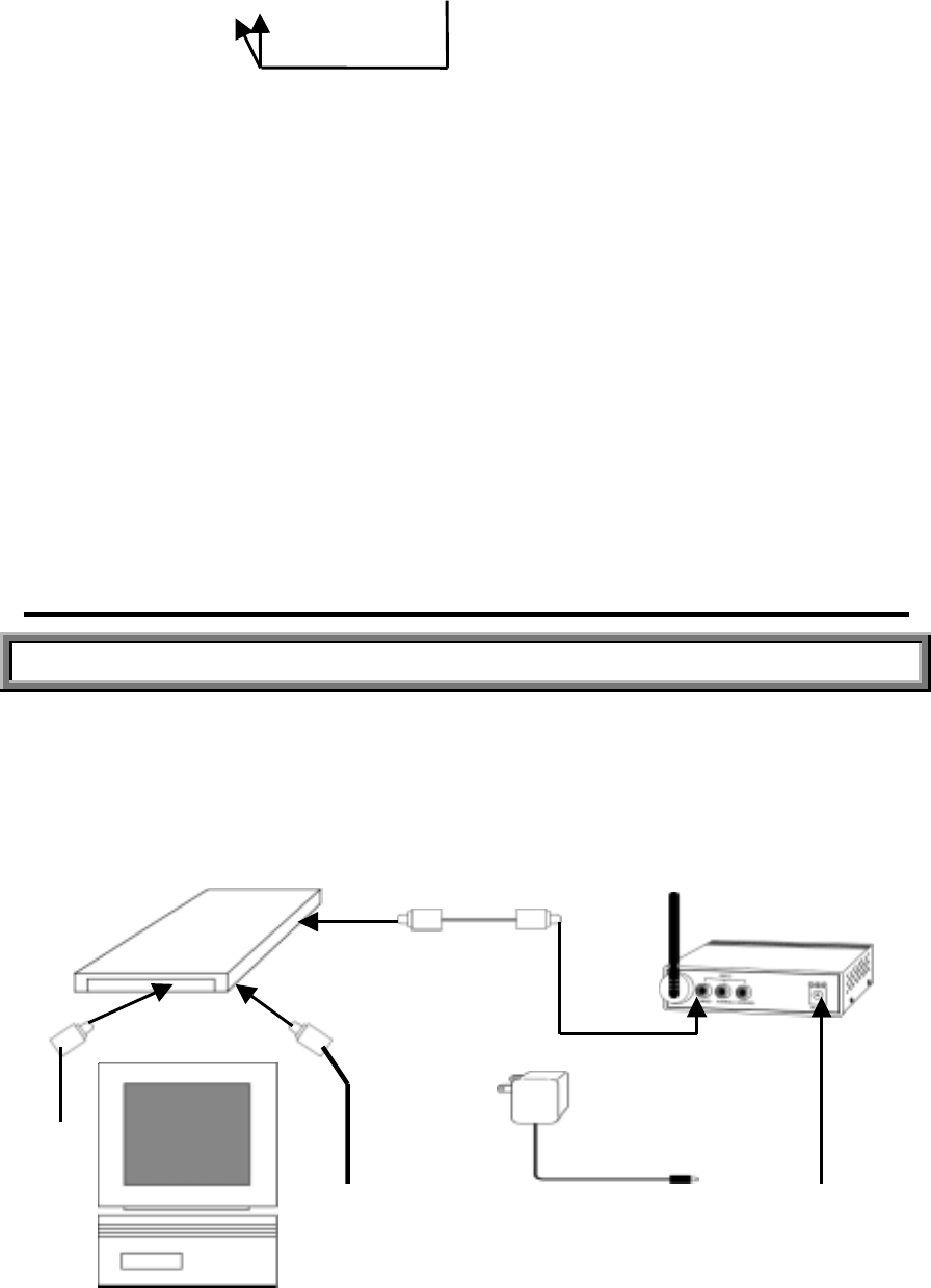
TRANSMITTING AUDIO/VIDEO FROM YOUR COMPUTER
This system also sends images and sounds from the computer to any TV in your home or office by using
a sound card and a VGA-to-TV converter (both can be purchased at the local computer store). This
feature allows you to send A/V signals from your desktop or laptop computer to a large TV screen for
presentation without running cables.
VGA-to-TV Converter
RCA Cable(optional)
12V 500mA
AC Adapto
r
VGA Extension
Cable
Note: Be sure to set the Power Switch on the transmitter to "OFF" before following
steps below.
1. Connect the monitor cable of your computer to the VGA Out port on
the VGA-to-TV converter.
2. Connect a VGA extension cable (supplied with converter) to the VGA port on your
CPU unit and the VGA In port on the VGA-to-TV converter.
3. Connect one end of the RCA cable (Yellow Plug) to the Video jack on the
VGA-to-TV converter, and the other end (Yellow plug) to the Video jack on
the transmitter.
4. Connect the 3.5mm stereo plug (of the Stereo-to Dual RCA cable) to the sound card,
and the dual RCA plug (of the Stereo-to Dual RCA cable) to the Audio-L/R
jacks on the transmitter.
5. Turn on the transmitter and search the channel 1-4 by pressing the Channel Selector,
and select the best one for optimum reception in your area.
Note: Both transmitter and receiver units must be set to the same channel.
6. Adjust the antenna direction as necessary.
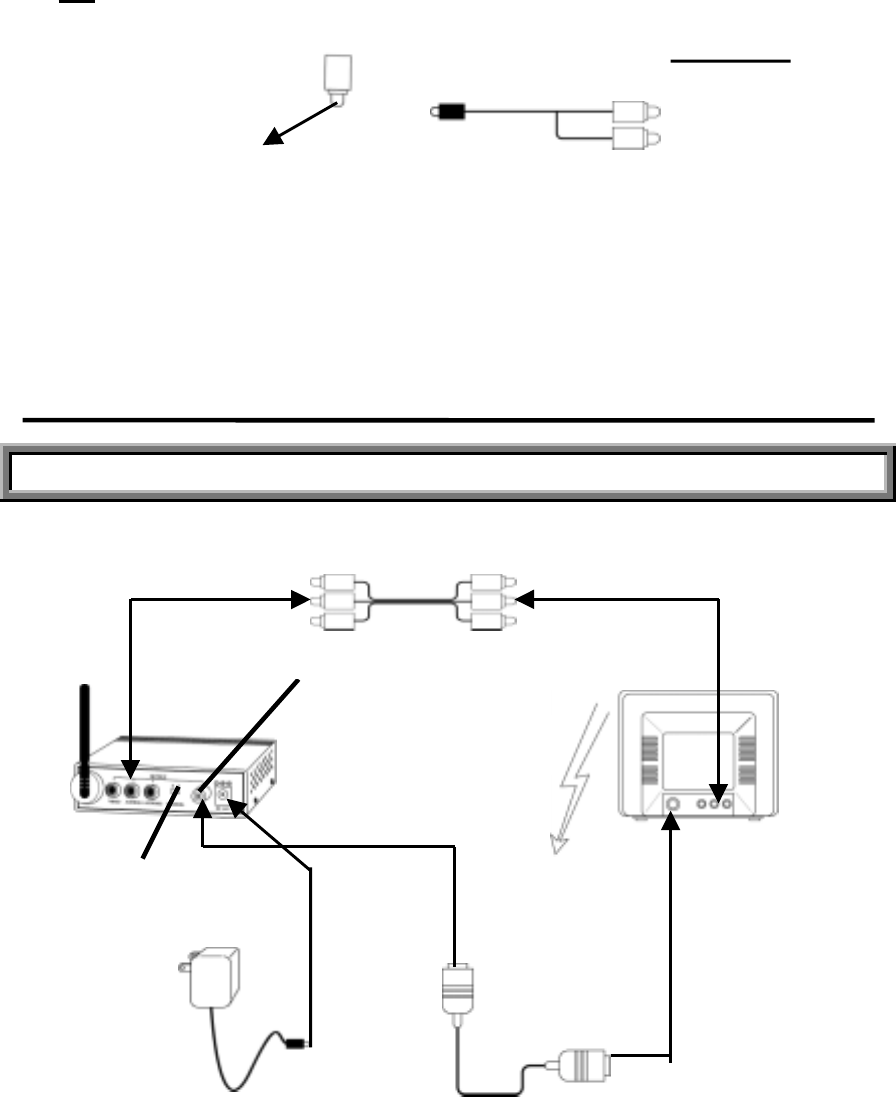
INSTALLATION OF WIRELESS RECEIVER
RECEIVING AUDIO/VIDEO ON REMOTE TV
Both units can be connected by either the RCA cable or RF cable.
RECEIVER RCA Cable(1.2M)
RF Channel
Selector (Switch)
Monito
r
Cable
Stereo-to Dual
RCA Cable(optional)
RF Out
p
ut Jac
k
Cable TV
Input Source
Rear side of the TV
12V 500mA
AC Adapto
r
Antenna Cable
RF Cable(1.2M)

Note: Be sure to set the power switch on the receiver to "OFF" before following steps
below.
1. Connect one end (triple plugs) of the RCA cable to the A/V jacks on the Receiver,
and the other end to the A/V In jacks on your TV.
Be sure to match the color of the plugs in both connection.
If your TV has a single Audio Input jack, connect white RCA plugs (Audio-L) in
both connection.
2. Turn on the receiver and set your TV to Video mode to view the receiving A/V
signal from the receiver.
3. If your TV has a single input port (Antenna Input jack) you can connect both
units with the RF cable. Connect one end of the RF cable to the Antenna In jack on
your TV and the other end to the RF Out jack on the receiver unit.
4. Set the RF channel selector on the receiver to Ch3 or Ch4 whichever is not used in
your area. Set your TV channel corresponding to the selected channel on the receiver.
INSTALLATION OF WIRELESS RECEIVER
RECEIVING AUDIO/VIDEO ON REMOTE TV (Cont'd)
5. Search the channel 1-4 by pressing the Channel Selector on the receiver and select
the best one for optimum reception in your area.
Note: Both transmitter and receiver units must be set to the same channel.
6. Adjust the antenna direction as necessary.
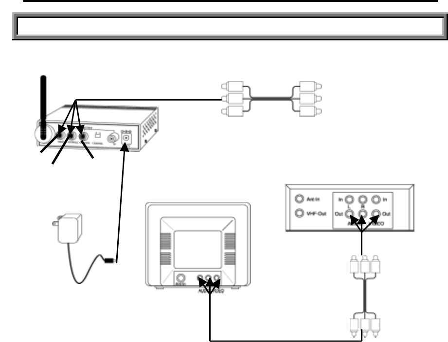
INSTALLATION OF WIRELESS RECEIVER
RECEIVING AUDIO/VIDEO ON REMOTE TV THROUGH VCR
Both units can be connected by either the RCA cable or RF cable.
RECEIVER RCA Cable(1.2M)
Cable TV
Input Source
Note: Be Sure to set the Power Switch on the receiver to "OFF" before processing as
follows.
1. Connect one end (triple plugs) of the RCA cable to the A/V jacks on the receiver,
and the other end to the A/V jacks on your VCR. Be sure to match the color of
the plugs in both connection.
If your VCR has a single audio input jack, connect white RCA plugs (Audio-L) in
both connection.
2. Connect one end of another RCA cable to the A/V jacks on your TV, and the other
end to the A/V jacks on your VCR.
VIDEO
AUDIO(L) AUDIO(R) DC IN JAC
K
Reaar side of the TV
12V 500mA
AC Adapto
r
RCA Cable
(optional)
3. Turn on the receiver and Set your TV to the Video mode to view the receiving
signal from the receiver.
4. Search the channel 1-4 by pressing the Channel Selector on the receiver and select
the best one for optimum reception in your area.
Note: Both transmitter and receiver units must be set to the same channel.
5. Adjust the antenna direction as necessary.
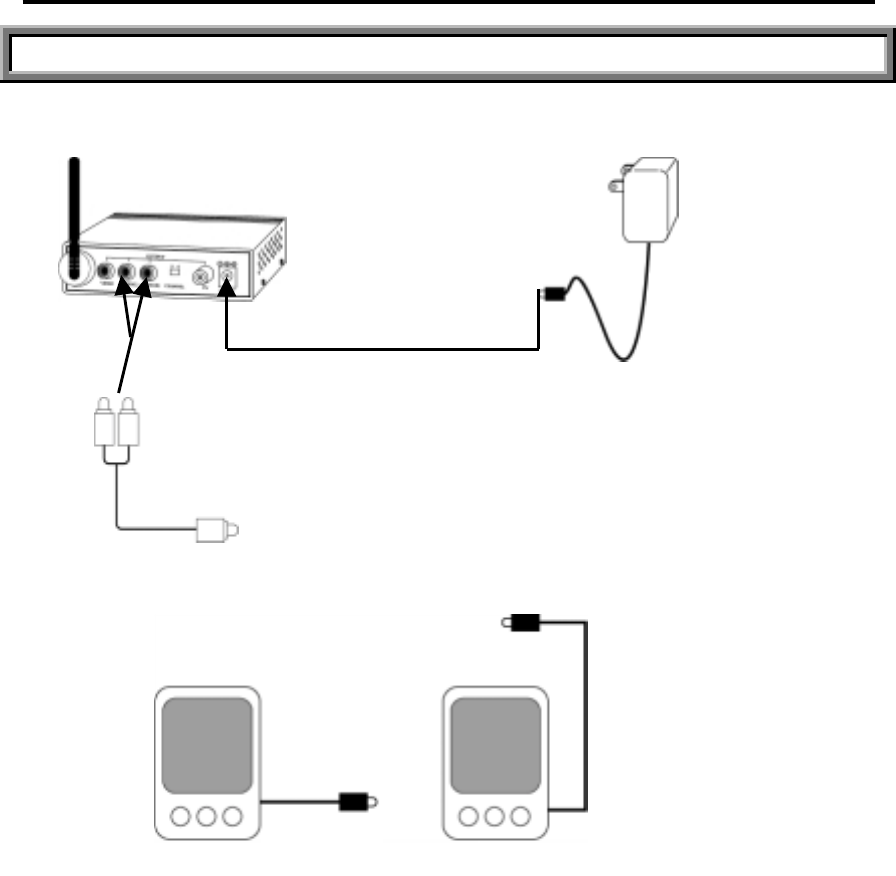
INSTALLATION OF WIRELESS RECEIVER
RECEIVING AUDIO ON REMOTE AMPLIFIED SPEAKERS
RECEIVER 12V 500mA
AC Adaptor
DC IN JACK
L-Speaker R-Speaker
Note: Be Sure to set the Power Switch on the receiver to "OFF" before following steps
below.
1. Connect a 3.5mm stereo jacks-to dual RCA plug cable(optional) to the receiver and
right speaker.
Stereo Jack-to
Dual RCA Plug Cable(optional)
L-Speaker
Cable
R-Speaker
Cable
2. Connect the speaker cable to the R-Speaker.
3. Turn on the receiver. Search the channel 1-4 by pressing Channel Selector on the
receiver and select the best one for optimum reception in your area.
Note: Both transmitter and receiver units must be set to the same channel.
4. Adjust the antenna direction as necessary.
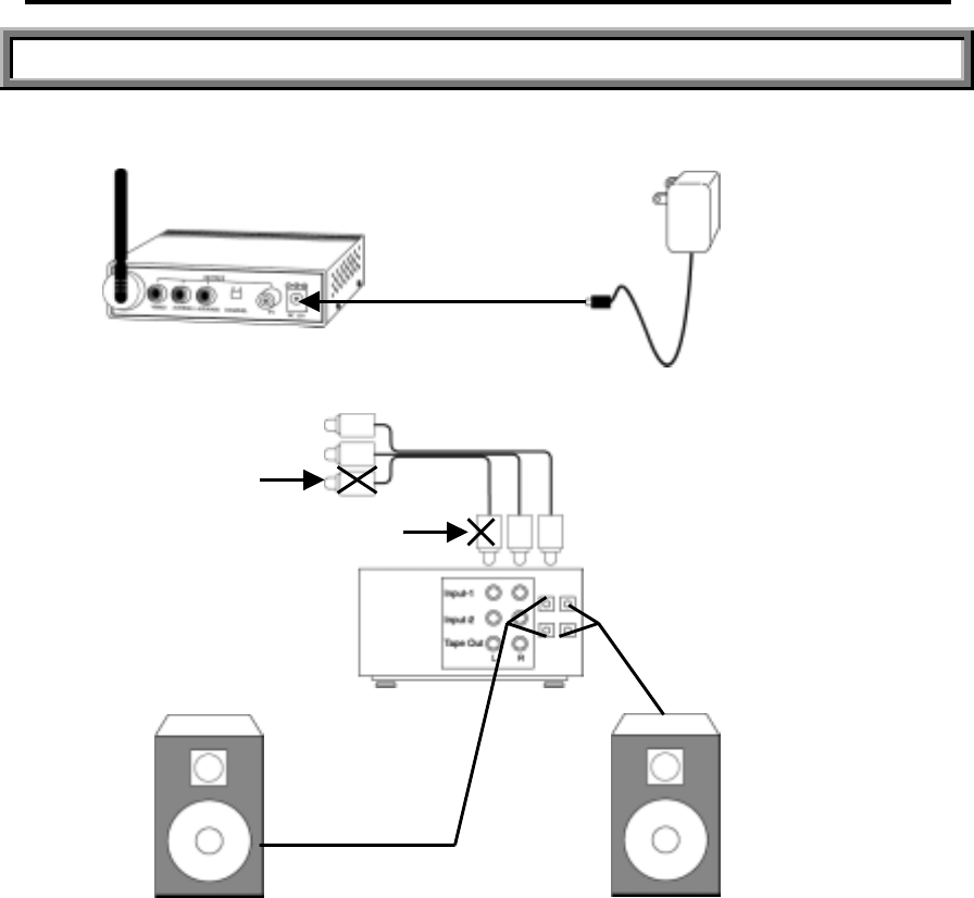
INSTALLATION OF WIRELESS RECEIVER
RECEIVING AUDIO ON ANY REMOTE SPEAKERS
RECEIVER 12V 500mA
AC Adaptor
L-Speaker R-Speaker
Note: Be Sure to set the Power Switch on the receiver to "OFF" before following steps
below.
1. Connect one end of the RCA cable to the Audio L/R jacks on the receiver and the
other end to the Audio L/R jacks on your stereo receiver or amplifier unit.
2. Connect the cable of your speakers to your stereo receiver or amplifier as usual.
3. Turn on the receiver. Search the channel 1-4 by pressing Channel Selector on the
receiver and select the best one for optimum reception in your area.
Note: Both transmitter and receiver units must be set to the same channel.
4. Adjust the antenna direction as necessary.
VIDEO
VIDEO
RCA Cable
(
o
p
tional
)
Rear of the Stereo
Receiver or Amplifie
r
L-S
p
eaker Cable
R-S
p
eaker Cable
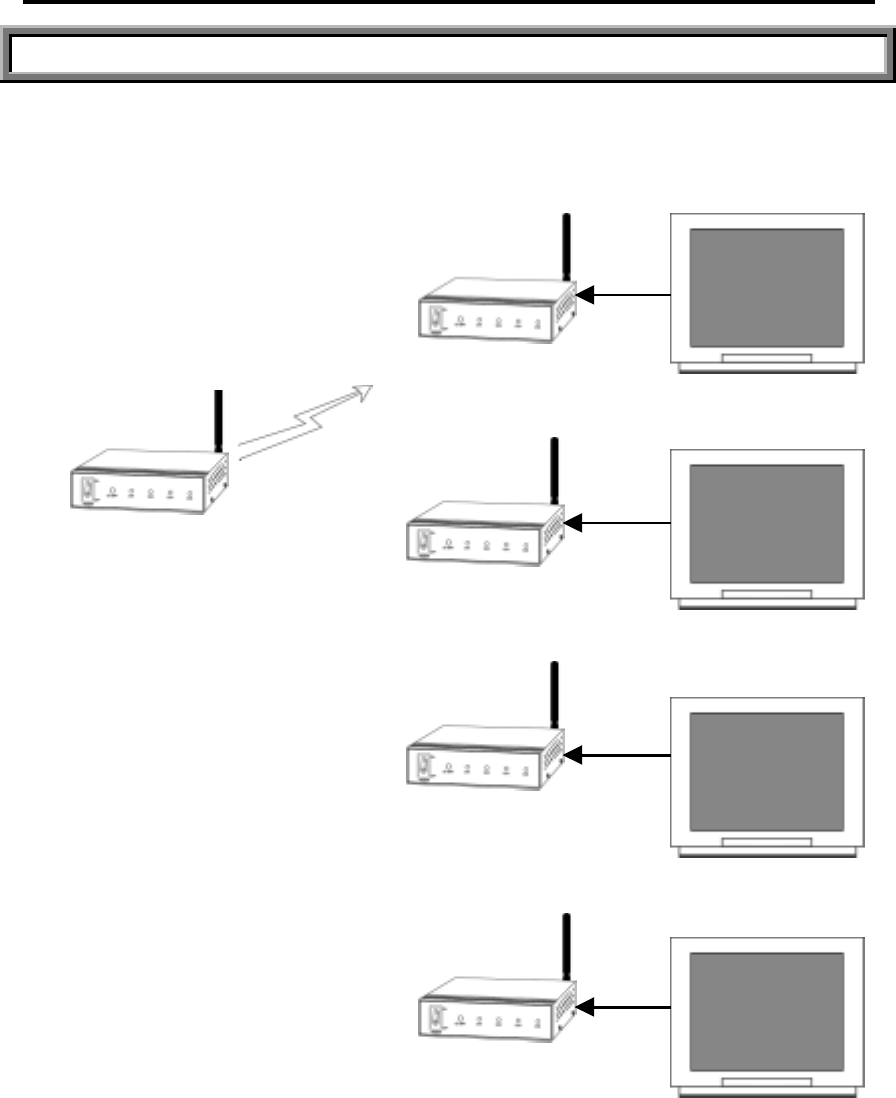
MULTIPLE CHANNEL OPERATION
ONE TRANSMITTER AND MULIPLE RECEIVER OPERATION
You can transmit the A/V signal to several A/V equipments in a remote location at the same time by
using one wireless transmitter with multiple wireless receivers as many as you want.
RECEIVER-1
TV
RECEIVER-2
RECEIVER-3
RECEIVER-4
TV
TV
TV
TRANSMITTER

MULTIPLE CHANNEL OPERATION
ONE TRANSMITTER AND MULIPLE RECEIVER OPERATION (Con'd)
Note: Be sure to set the Power Switch on the transmitter and receiver to "OFF" before
following steps below.
1. Connect all receiver units to your TV with or without VCR using the RCA cable
(see instructions on page 8).
Note: This system includes only one receiver unit and additional units are optional.
See the enclosed order form for additional order.
2. Turn on your transmitter and select one of the transmission channel 1-4
(corresponding to the receiver) by pressing the Channel Selector on the transmitter
unit.
3. Turn on all TVs which are connected to the receiver unit and set your TV to video mode.
4. Turn on all receiver units and search the channel 1-4 by pressing the Channel
Selector on the receiver, and select the best one for optimum reception in your area.
Note: All receiver and transmitter units must be set to the same channel.
5. Adjust the antenna direction as necessary.
MULTIPLE CHANNEL OPERATION
ONE RECEIVER AND MULTIPLE TRANSMITTER OPERATION (Con'd)
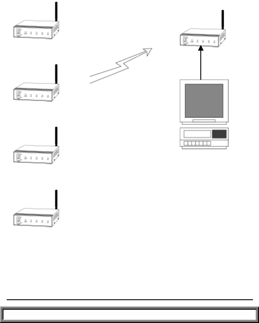
You can receive signals from several transmitters in a remote location with one wireless receiver. You
can watch 4 different A/Vs by pressing the Channel Selector on the receiver.
TRANSMITTER
MULTIPLE CHANNEL OPERATION
ONE RECEIVER AND MULTIPLE TRANSMITTER OPERATION (Con'd)
Note: Be sure to set the Power Switch on the transmitter and receiver to "OFF" before
CH1
CH2
CH3
CH4
RECEIVER
TV
VCR

following steps below.
1. Connect the receiver unit to your TV with or without the VCR by using the RCA
cable. (see instructions on 8)
2. Turn on all of transmitters. The transmitters must be set to different channels. Select
the channel 1-4 for each unit by pressing the Channel Selector on each transmitter.
3. Turn on your remote TV that is connected to the receiver. Set your TV to video
mode.
4. Turn on the receiver.
5. You can select the channel 1-4 one by one manually by pressing the Channel
Selector on the receiver. Your TV will display the signals from different transmitters
as selected.
6. Adjust the antenna direction as necessary.
TROUBLESHOOTING
IF THE SYSTEM DOES NOT FUNCTION PROPERLY, CHECK THE
FOLLOWING POINTS BEFORE CONTACT WITH THE SERVICE CENTER
Problem Causes and remedies
- AC adapter not plugged in or improper adapter
connection
- Power switches on the transmitter and receiver not
N
o powe
r
(no picture/sound)

turned on.
- Power switches on the TV not turned on.
- Improper A/V cable connection.
- Adjust the transmitter & receiver antenna direction.
- Improper channel 1-4 selection.
SPECIFICATIONS
TRANSMITTER WITH CAMERA
FREQUENCY RANGE 2400 ~ 2483.5 MHz
POWER SUPPLY DC 12V
RF OUTPUT POWER 10mW(optional)
SPURIOUS EMISSION -40 dBc
OUTPUT IMPEDANCE 50Ω NOMINAL
OPERATING TEMPERATUR -10~ +60
POWER CONSUMPTION 200 mA
WEIGHT 390g
SIZE (except antenna) 116(L) X 111(W) X32(H)
Poor rece
p
tio
n

RECEIVER
RECEIVING METHOD HETERODYNE
DEMODULATION METHOD FM
OSCILLATION METHOD PLL
AUDIO RESPONSE 300-3000 Hz
SENSITIVITY ≤-80 dBm
TV MODULATOR NTSC OR PAL
VIDEO OUTPUT 1V P-P (COMPOSITE SIGNAL)
AUDIO OUTPUT 1V P-P
POWER SUPPLY DC 12V
POWER CONSUMPTION 400 mA
WEIGHT 440g
SIZE (except antenna) 116(L) X 111(W) X 32(H)