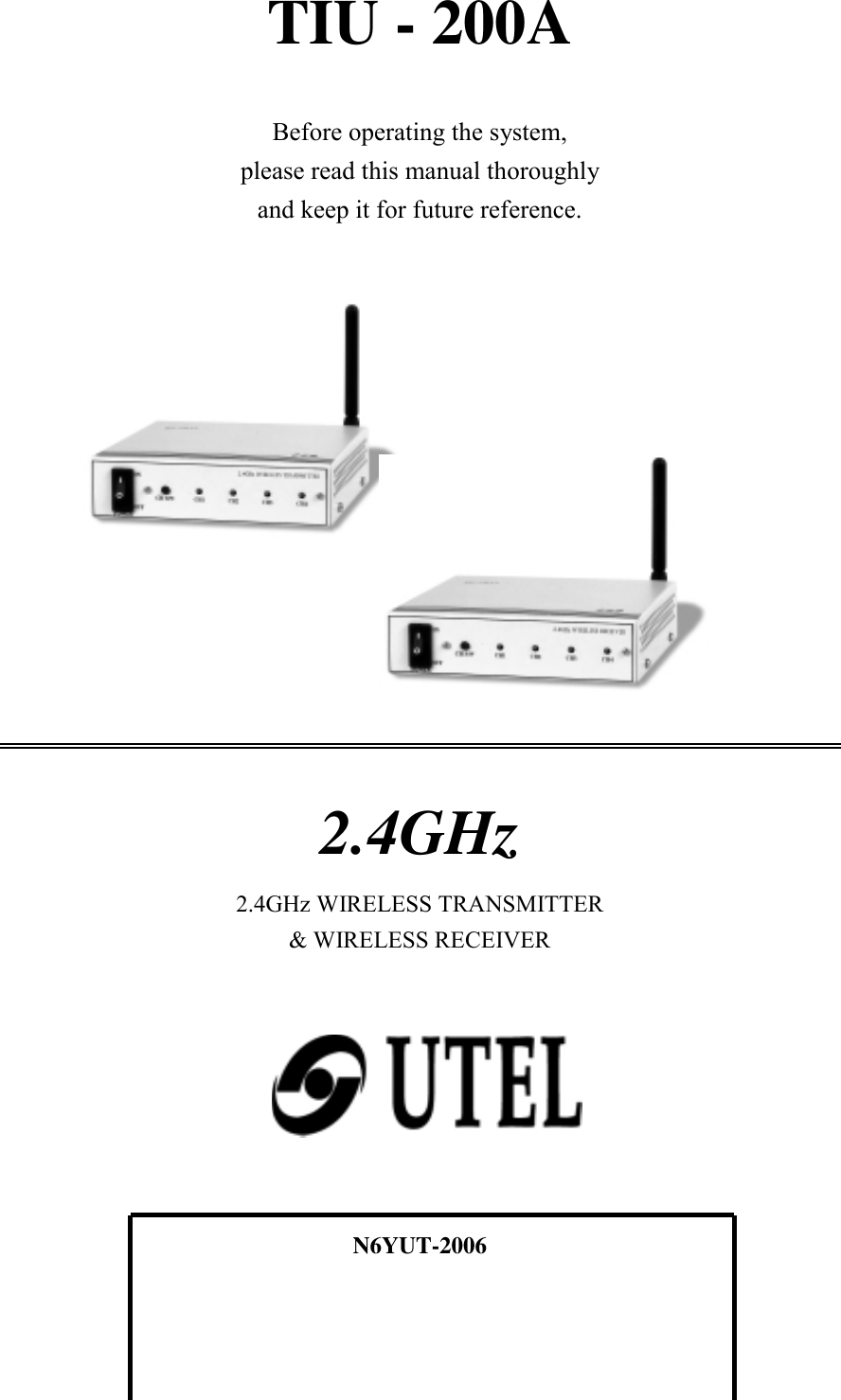
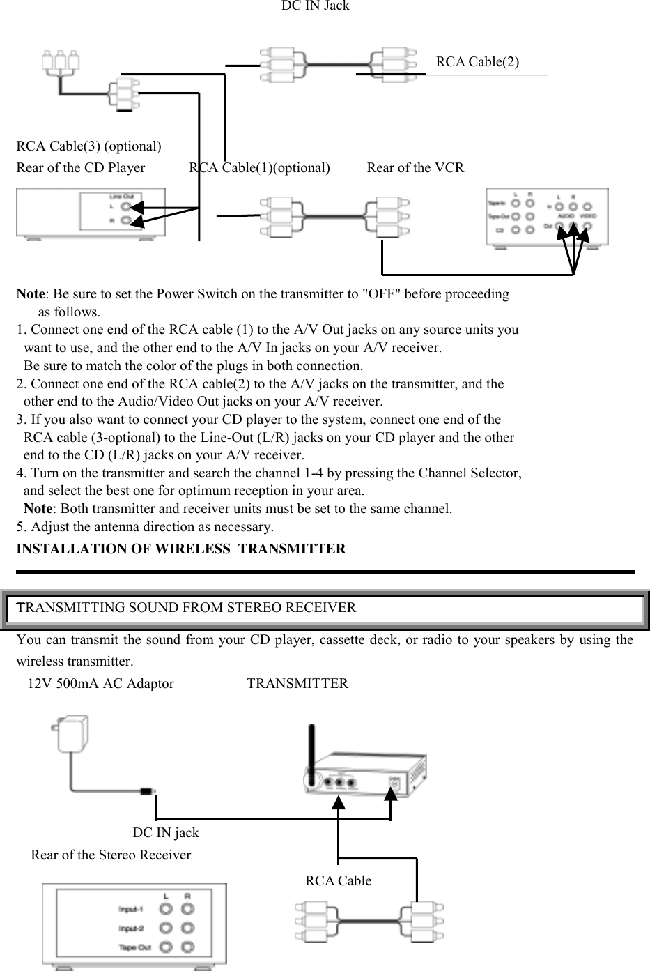
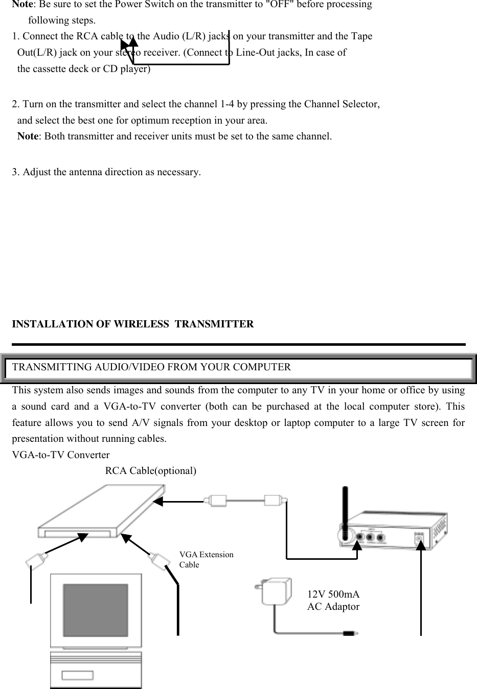
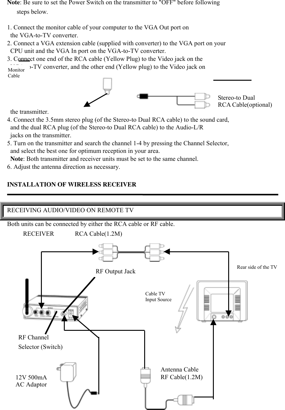
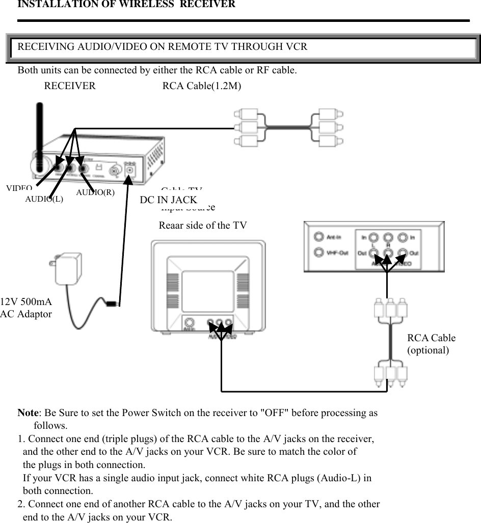
Utel UT-2006 Audio and Video Transmitter User Manual Manual

Utel Co. Ltd. Audio and Video Transmitter Manual

Manual

TIU - 200ABefore operating the system,please read this manual thoroughlyand keep it for future reference.2.4GHz2.4GHz WIRELESS TRANSMITTER& WIRELESS RECEIVERN6YUT-2006
UTEL CO.,LTDTIU-200ATHIS DEVICE COMPLIES WITH PART 15 OF THE FCC RULES.OPERATION IS SUBJECT TO THE FOLLOWING TWO CONDITIONS:(1) THIS DEVICE MAY NOT CAUSEHARMFUL INTERFERENCE, AND(2) THIS DEVICE MUST ACCEPT ANYINTERFERENCE RECEIVED,INCLUDING INTERFERENCE THAT MAYCAUSE UNDESIRED OPERATION.Caution: Any changes or modifications inconstruction of this device which are notexpressly approved by the party responsiblefor compliance could void the usersauthority to operate the equipment.CONTENTS1. SUB - ASSY'S IN THIS UNIT - - - - - - - - - - - - - - - - - - - - -   12. CONTROLS AND FUNCTIONS - - - - - - - - - - - - - - - - - - - - - - -  2
3. INSTALLATION  - - - - - - - - - - - - - - - - - - - - - - - - - - -   4    3-1. INSTALLATION OF WIRELESS TRANSMITTER  - - - - - - - - - - - -   6    3-2. INSTALLATION OF WIRELESS RECEIVER - - - - - - - - - - - - - -  144. MULTIPLE CHANNEL OPERATION - - - - - - - - - - - - - - - - - - - -   195. TROUBLESHOOTING  - - - - - - - - - - - - - - - - - - - - - - - - -   236. SPECIFICATIONS  - - - - - - - - - - - - - - - - - - - - - - - - -    24SUB - ASSY'S IN THIS UNITStandard package         TIU-200A                           1- Transmitter                           1- UL Approved AC adaptor                           1- RCA A/V cable                           1- User's manual                          RIU-100AN / 100AP                           1- Receiver                           1- UL approved AC adaptor                           1- RCA A/V cable                           1- RF cable
Optional Items            Extra wireless transmitter(Not included)            Extra wireless receiver                          CCD Video Camera                          Extra RCA A/V cable                          Extra RF cable                          Warranty registration cardCHECK LIST PRIOR TO USE CHECK THESE INSTRUCTIONS BELOW BEFORE OPERATING THIS UNIT.1. Keep distance at least 10 feet between the transmitter and receiver when you  install it because high frequency radio waves of 2.4GHz may cause an interfering  problem between channels, which is the reason of the distorted picture on the monitor.2. Turn and adjust the antenna of the transmitter and receiver in order to optimize  the picture condition. Be aware that maximum scope of turning the antenna is 90°  towards right and left. Therefore, Do not turn it over 90°to prevent breakage.3. Be sure to adjust the adaptor correctly to the exact power (120V or 220V you are  using) before installation.FOR EFFICIENT USE1. External radio waves may cause an interfering problem and geographical features  may affect the communication distance.2. Keep in mind the usage of instructions for effective maintenance of your camera.CONTROLS AND FUNCTIONSWIRELESS TRANSMITTER            FRONT VIEW                                REAR VIEW                                  1       2   3     4                                 5  6          71. 2.4GHz A/V ANTENNA
  The high gain directional dipole antenna sends the A/V modulated RF signal to the  receiver.2. POWER SWITCH  Controls power on/off. Be sure to set the switch to "OFF" before plugging the  AC adaptor into the unit and AC outlet.3. CHANNEL SELECTOR  Push button switch for channel selection4. LED CHANNEL INDICATORS  Indicators of selected channel5. VIDEO INPUT JACK (Yellow)  RCA jack for video input source connection6. AUDIO INPUT JACKS (Left : White, Right : Red)  RCA L/R jacks for Audio input source connection7. DC IN JACK  Connect the supplied 12V 500mA AC adaptorCONTROLS AND FUNCTIONSWIRELESS RECEIVER             FRONT VIEW                              REAR VIEW             2  3    4                             5  6   7  8  91. 2.4GHz A/V ANTENNA  The high gain directional dipole antenna receives the RF signal.2. POWER SWITCH  Controls power on/off. Be sure to set the switch to "OFF" before plugging the  AC adaptor into the unit and AC outlet.3. CHANNEL SELECTOR  Push button switch for channel selection4. LED CHANNEL INDICATORS  Indicators of selected channel1
5. VIDEO OUTPUT JACK (Yellow)  RCA jack for video output6. AUDIO OUTPUT JACK (Left : White, Right: Red)  RCA L/R jacks for Audio output7. RF CHANNEL SELECTOR  Channel 3,4 selector to operate with TV(NTSC Standard)8. RF OUTPUT CONNECTOR  Connector for TV connection9. DC IN JACK  Power supply for 12V 500mA AC adaptorINSTALLATIONWIRELESS TRANSMITTER    DC 12V 500mA    AC ADAPTOR                                                Transmitting From1. Place the wireless transmitter on or near the A/V source unit.2. Connect the 500mA AC adaptor to the DC IN jack on the receiver and plug it  into the 120V AC outlet.WIRELESS RECEIVER      DC 12V 500mA      AC ADAPTOR.Satellite Receiver   .Camcorder.Cable TV         .Surveillance Camera.VCR             .Computer.Laser Disc Player   (convertible card required).Wireless Cable     .A/V Receiver.Digital Video Disc  .CD Player
Connects to·TV·Monitor·Computer (convertible card required )·Speakers1. Place the wireless receiver on or near the TV, monitor or other A/V unit.2. Connect the 500mA AC adaptor to the DC IN jack on the receiver and plug it  into the 120V AC outlet.INSTALLATIONADJUSTING ANTENNA OF UNIT                             RF ANTENNAWARNING!Please do not turn the antenna towards  the same way more than 90 degrees.TRANSMITTER
      IMPORTANT NOTE FOR CHANNEL SELECTION      Search the CH 1-CH 4 and select the best one for optimum reception in      your area. Both transmitter and receiver must be set to the same channel.INSTALLATION OF WIRELESS TRANSMITTERTHE MAXIMUM RANGE IS 300 FT WITHOUT LOSS OF ANY PICTURE / SOUND QUALITY      12V 500mA      AC Adaptor                             TRANSMITTER                                                         RCA cable(Optional)                                                    Rear OF VCR   Rear of TV         RF CableNote: Be sure to set the power on the transmitter to "OFF" before following steps      below.1. Connect one end (triple plugs) of the RCA cable to the A/V jacks on the transmitter,  and the other end to the Audio/Video Out jacks on your VCR.  Be sure to match the color of the plugs in both connection.  If your VCR has only one audio out jack (mono sound), connect the white  plug(Audio-L) to your VCR.2. If you want to use the system with a nearby TV, connect one end of the supplied  RF cable to the VHF Out jack on your VCR, and the other end to the antenna In  jack on your TV.3. To receive cable transmission on your TV without the cable converting box, connect  the cable TV input source to the VHF In jack on your VCR.4. Turn on the transmitter and search the channel 1-4 by pressing the Channel selector,
  and then select the best one for optimum reception in your area.5. Adjust the antenna direction as necessary.INSTALLATION OF WIRELESS TRANSMITTER      12V 500mA    AC Adaptor                          TRANSMITTER                                                     RCA cable                                                   Rear OF the Cable Converting Box    Rear of TV           RF CableNote: Be sure to set the power on the transmitter to "OFF" before proceeding as      follows.1. Connect one end of the RCA cable to the A/V jacks on the transmitter, and the  other end to the A/V Out jacks on your cable converting box.  Be sure to match the color of the plugs in both connection.  If your cable converting box has only one audio OUT jack, connect the white plug  to your cable converting box.2. For viewing cable signals through the nearby TV, connect the RF cable to the  Antenna Out jack on your converting box and the Antenna In jack on your TV.3. Turn on the transmitter and search the channel 1-4 by pressing the Channel Selector,  and select the best one for optimum reception in your area.  Note: Both transmitter and Receiver units must be set to the same channel.4. Adjust the antenna direction as necessary.
INSTALLATION OF WIRELESS TRANSMITTER    12V 500mA    AC Adaptor                       TRANSMITTER                                           RCA cable                                                    Rear of the Satellite ReceiverRear of the TV          RF Cable                    (or Laser Disc Player)Note: Be sure to set the Power Switch on the transmitter to "OFF" before following      steps below.1. Connect one end of the RCA cable to the A/V jacks on the transmitter, and the other  end to the Audio/Video Out jacks on your satellite receiver or laser disc player.  Be sure to match the color of the plugs in both connection.2. Connect the RF cable to the Antenna Out jack on the satellite receiver (or laser disc  player) and the Antenna In jack on your TV.3. Turn on the transmitter and search the channel 1-4 by pressing the Channel Selector,  and select the best one for optimum reception in your area.  Note: Both transmitter and receiver units must be set to the same channel.4. Adjust the antenna direction as necessary.INSTALLATION OF WIRELESS  TRANSMITTER
TRANSMITTING AUDIO/VIDEO FROM CAMCORDERThe system can be used with any camcorder as a wireless monitoring system. DC 12V 500mA AC Adaptor                                                      DC IN jack          CamcorderVideoAudio-L  Audio-RNote: Be sure to set the Power Switch on the transmitter to "OFF" before following      steps below.1. Place your camcorder near the object you want to monitor such as a sleeping baby,  the playing children, the elderly, or the disabled.2. Connect one end(triple plugs) of the RCA cable to the A/V jacks on the transmitter,  and the other end to the A/V Out jacks on your camcorder.  Be sure to match the color of the plugs in both connection.  If your camcorder has only one Audio Out jack (mono sound), connect the white  plug(Audio-L) to the single audio out jack on your camcorder.  Note: Some camcorders require the adaptor patch cable.3. Turn on the transmitter and search the channel 1-4 by pressing the Channel selector,  and select the best one for optimum reception in your area.  Note: Both transmitter and receiver units must be set to the same channel.4. Adjust the antenna direction as necessary.INSTALLATION OF WIRELESS  TRANSMITTERTRANSMITTING AUDIO/VIDEO FROM CCD VIDEO CAMERAThe system can be used with the CCD Video Camera (optional-see order from) as aRCA Cable
wireless monitoring system for your home or business security.  Rear of the Camera                                       TRANSMITTER                                                                       DC IN jack                                                                       12V 500mA                                                                       AC AdaptorNote: Be sure to set the Power Switch on the transmitter to"OFF" before following steps below.1. Place optional CCD camera near the object you want to monitor such as a sleeping baby, the playingchildren, the olderly, or the disabled.2. Connect one end of the RCA cable to the Audio(L)/Video jacks on the transmitter,  and the other end to the A/V Out jacks on the camera cable assembly on the optional  camera. Be sure to match the color of the plugs in both connection.3. Turn the transmitter on and Search the channel 1-4 by pressing the Channel Selector  on the transmitter, and select the best one for optimum reception in your area.  Note: Both transmitter and receiver units must be set to the same channel.4. Adjust the antenna direction as necessary.INSTALLATION OF WIRELESS  TRANSMITTERTRANSMITTING AUDIO/VIDEO FROM CCD VIDEO CAMERAYou can transmit signals from several A/V sources to a remote location by using the wireless transmitterwith A/V receivers that have multiple input and output jacks.Rear of the A/V Receiver        12V 500mA AC Adaptor           TRANSMITTERCamera Cable AssemblyVideo Out (Yellow)Audio Out(White)DC In12V 500mAAC Adaptor(Optional) Audio(R)
                                                                         DC IN Jack                         RCA Cable(3) (optional)Rear of the CD Player            RCA Cable(1)(optional)          Rear of the VCRNote: Be sure to set the Power Switch on the transmitter to "OFF" before proceeding      as follows.1. Connect one end of the RCA cable (1) to the A/V Out jacks on any source units you  want to use, and the other end to the A/V In jacks on your A/V receiver.  Be sure to match the color of the plugs in both connection.2. Connect one end of the RCA cable(2) to the A/V jacks on the transmitter, and the  other end to the Audio/Video Out jacks on your A/V receiver.3. If you also want to connect your CD player to the system, connect one end of the  RCA cable (3-optional) to the Line-Out (L/R) jacks on your CD player and the other  end to the CD (L/R) jacks on your A/V receiver.4. Turn on the transmitter and search the channel 1-4 by pressing the Channel Selector,  and select the best one for optimum reception in your area.  Note: Both transmitter and receiver units must be set to the same channel.5. Adjust the antenna direction as necessary.INSTALLATION OF WIRELESS  TRANSMITTERTRANSMITTING SOUND FROM STEREO RECEIVERYou can transmit the sound from your CD player, cassette deck, or radio to your speakers by using thewireless transmitter.   12V 500mA AC Adaptor                    TRANSMITTER                                DC IN jack    Rear of the Stereo ReceiverRCA Cable(2)RCA Cable
Note: Be sure to set the Power Switch on the transmitter to "OFF" before processing      following steps.1. Connect the RCA cable to the Audio (L/R) jacks on your transmitter and the Tape  Out(L/R) jack on your stereo receiver. (Connect to Line-Out jacks, In case of  the cassette deck or CD player)2. Turn on the transmitter and select the channel 1-4 by pressing the Channel Selector,  and select the best one for optimum reception in your area.  Note: Both transmitter and receiver units must be set to the same channel.3. Adjust the antenna direction as necessary.INSTALLATION OF WIRELESS  TRANSMITTERTRANSMITTING AUDIO/VIDEO FROM YOUR COMPUTERThis system also sends images and sounds from the computer to any TV in your home or office by usinga sound card and a VGA-to-TV converter (both can be purchased at the local computer store). Thisfeature allows you to send A/V signals from your desktop or laptop computer to a large TV screen forpresentation without running cables.VGA-to-TV Converter                                   RCA Cable(optional)12V 500mAAC AdaptorVGA ExtensionCable
Note: Be sure to set the Power Switch on the transmitter to "OFF" before following      steps below.1. Connect the monitor cable of your computer to the VGA Out port on  the VGA-to-TV converter.2. Connect a VGA extension cable (supplied with converter) to the VGA port on your  CPU unit and the VGA In port on the VGA-to-TV converter.3. Connect one end of the RCA cable (Yellow Plug) to the Video jack on the  VGA-to-TV converter, and the other end (Yellow plug) to the Video jack on  the transmitter.4. Connect the 3.5mm stereo plug (of the Stereo-to Dual RCA cable) to the sound card,  and the dual RCA plug (of the Stereo-to Dual RCA cable) to the Audio-L/R  jacks on the transmitter.5. Turn on the transmitter and search the channel 1-4 by pressing the Channel Selector,  and select the best one for optimum reception in your area.  Note: Both transmitter and receiver units must be set to the same channel.6. Adjust the antenna direction as necessary.INSTALLATION OF WIRELESS RECEIVERRECEIVING AUDIO/VIDEO ON REMOTE TVBoth units can be connected by either the RCA cable or RF cable.          RECEIVER             RCA Cable(1.2M)                                                    RF Channel       Selector (Switch)MonitorCableStereo-to DualRCA Cable(optional)RF Output JackCable TVInput SourceRear side of the TV12V 500mAAC AdaptorAntenna CableRF Cable(1.2M)
Note: Be sure to set the power switch on the receiver to "OFF" before following steps      below.1. Connect one end (triple plugs) of the RCA cable to the A/V jacks on the Receiver,  and the other end to the A/V In jacks on your TV.  Be sure to match the color of the plugs in both connection.  If your TV has a single Audio Input jack, connect white RCA plugs (Audio-L) in  both connection.2. Turn on the receiver and set your TV to Video mode to view the receiving A/V  signal from the receiver.3. If your TV has a single input port (Antenna Input jack) you can connect both  units with the RF cable. Connect one end of the RF cable to the Antenna In jack on  your TV and the other end to the RF Out jack on the receiver unit.4. Set the RF channel selector on the receiver to Ch3 or Ch4 whichever is not used in  your area. Set your TV channel corresponding to the selected channel on the receiver.INSTALLATION OF WIRELESS  RECEIVERRECEIVING AUDIO/VIDEO ON REMOTE TV (Cont'd)5. Search the channel 1-4 by pressing the Channel Selector on the receiver and select  the best one for optimum reception in your area.  Note: Both transmitter and receiver units must be set to the same channel.6. Adjust the antenna direction as necessary.
INSTALLATION OF WIRELESS  RECEIVERRECEIVING AUDIO/VIDEO ON REMOTE TV THROUGH VCRBoth units can be connected by either the RCA cable or RF cable.          RECEIVER                         RCA Cable(1.2M)                                                      Cable TV                                                      Input SourceNote: Be Sure to set the Power Switch on the receiver to "OFF" before processing as      follows.1. Connect one end (triple plugs) of the RCA cable to the A/V jacks on the receiver,  and the other end to the A/V jacks on your VCR. Be sure to match the color of  the plugs in both connection.  If your VCR has a single audio input jack, connect white RCA plugs (Audio-L) in  both connection.2. Connect one end of another RCA cable to the A/V jacks on your TV, and the other  end to the A/V jacks on your VCR.VIDEOAUDIO(L) AUDIO(R) DC IN JACKReaar side of the TV12V 500mAAC AdaptorRCA Cable(optional)
3. Turn on the receiver and Set your TV to the Video mode to view the receiving  signal from the receiver.4. Search the channel 1-4 by pressing the Channel Selector on the receiver and select  the best one for optimum reception in your area.  Note: Both transmitter and receiver units must be set to the same channel.5. Adjust the antenna direction as necessary.INSTALLATION OF WIRELESS  RECEIVERRECEIVING AUDIO ON REMOTE AMPLIFIED SPEAKERS           RECEIVER                                  12V 500mA                                                     AC Adaptor                       DC IN JACK             L-Speaker                      R-Speaker                                                   Note: Be Sure to set the Power Switch on the receiver to "OFF" before following steps      below.1. Connect a 3.5mm stereo jacks-to dual RCA plug cable(optional) to the receiver and  right speaker.Stereo Jack-toDual RCA Plug Cable(optional)L-SpeakerCableR-SpeakerCable
2. Connect the speaker cable to the R-Speaker.3. Turn on the receiver. Search the channel 1-4 by pressing Channel Selector on the  receiver and select the best one for optimum reception in your area.  Note: Both transmitter and receiver units must be set to the same channel.4. Adjust the antenna direction as necessary.INSTALLATION OF WIRELESS  RECEIVERRECEIVING AUDIO ON ANY REMOTE SPEAKERS                RECEIVER                              12V 500mA                                                      AC Adaptor             L-Speaker                                R-SpeakerNote: Be Sure to set the Power Switch on the receiver to "OFF" before following steps      below.1. Connect one end of the RCA cable to the Audio L/R jacks on the receiver and the  other end to the Audio L/R jacks on your stereo receiver or amplifier unit.2. Connect the cable of your speakers to your stereo receiver or amplifier as usual.3. Turn on the receiver. Search the channel 1-4 by pressing Channel Selector on the  receiver and select the best one for optimum reception in your area.  Note: Both transmitter and receiver units must be set to the same channel.4. Adjust the antenna direction as necessary.VIDEOVIDEORCA Cable(optional)Rear of the StereoReceiver or AmplifierL-Speaker CableR-Speaker Cable
MULTIPLE CHANNEL OPERATIONONE TRANSMITTER AND MULIPLE RECEIVER OPERATIONYou can transmit the A/V signal to several A/V equipments in a remote location at the same time byusing one wireless transmitter with multiple wireless receivers as many as you want.                                         RECEIVER-1                                                                         TVRECEIVER-2RECEIVER-3RECEIVER-4TVTVTVTRANSMITTER
MULTIPLE CHANNEL OPERATIONONE TRANSMITTER AND MULIPLE RECEIVER OPERATION (Con'd)Note: Be sure to set the Power Switch on the transmitter and receiver to "OFF" before      following steps below.1. Connect all receiver units to your TV with or without VCR using the RCA cable  (see instructions on page 8).  Note: This system includes only one receiver unit and additional units are optional.  See the enclosed order form for additional order.2. Turn on your transmitter and select one of the transmission channel 1-4 (corresponding to the receiver) by pressing the Channel Selector on the transmitter unit.3. Turn on all TVs which are connected to the receiver unit and set your TV to video mode.4. Turn on all receiver units and search the channel 1-4 by pressing the Channel  Selector on the receiver, and select the best one for optimum reception in your area.  Note: All receiver and transmitter units must be set to the same channel.5. Adjust the antenna direction as necessary.MULTIPLE CHANNEL OPERATIONONE RECEIVER AND MULTIPLE TRANSMITTER OPERATION (Con'd)
You can receive signals from several transmitters in a remote location with one wireless receiver. Youcan watch 4 different A/Vs by pressing the Channel Selector on the receiver.    TRANSMITTERMULTIPLE CHANNEL OPERATIONONE RECEIVER AND MULTIPLE TRANSMITTER OPERATION (Con'd)Note: Be sure to set the Power Switch on the transmitter and receiver to "OFF" beforeCH1CH2CH3CH4RECEIVERTVVCR
      following steps below.1. Connect the receiver unit to your TV with or without the VCR by using the RCA  cable. (see instructions on 8)2. Turn on all of transmitters. The transmitters must be set to different channels. Select  the channel 1-4 for each unit by pressing the Channel Selector on each transmitter.3. Turn on your remote TV that is connected to the receiver. Set your TV to video  mode.4. Turn on the receiver.5. You can select the channel 1-4 one by one manually by pressing the Channel  Selector on the receiver. Your TV will display the signals from different transmitters  as selected.6. Adjust the antenna direction as necessary.TROUBLESHOOTINGIF THE SYSTEM DOES NOT FUNCTION PROPERLY, CHECK THEFOLLOWING POINTS BEFORE CONTACT WITH THE SERVICE CENTER       Problem                            Causes and remedies                               - AC adapter not plugged in or improper adapter                                 connection                               - Power switches on the transmitter and receiver not                    No power(no picture/sound)
                                 turned on.                               - Power switches on the TV not turned on.                               - Improper A/V cable connection.                               - Adjust the transmitter & receiver antenna direction.                               - Improper channel 1-4 selection.SPECIFICATIONSTRANSMITTER WITH CAMERAFREQUENCY RANGE 2400 ~ 2483.5 MHzPOWER SUPPLY DC 12VRF OUTPUT POWER 10mW(optional)SPURIOUS EMISSION -40 dBcOUTPUT IMPEDANCE 50Ω NOMINALOPERATING TEMPERATUR -10~ +60POWER CONSUMPTION 200 mAWEIGHT 390gSIZE (except antenna) 116(L) X 111(W) X32(H)Poor reception
RECEIVERRECEIVING METHOD HETERODYNEDEMODULATION METHOD FMOSCILLATION METHOD PLLAUDIO RESPONSE 300-3000 HzSENSITIVITY ≤-80 dBmTV MODULATOR NTSC OR PALVIDEO OUTPUT 1V P-P (COMPOSITE SIGNAL)AUDIO OUTPUT 1V P-PPOWER SUPPLY DC 12VPOWER CONSUMPTION 400 mAWEIGHT 440gSIZE (except antenna) 116(L) X 111(W) X 32(H)

Navigation menu