VALEO Telematik und Akustik WMI2W167 Wireless Mobile Interface User Manual
Peiker acustic GmbH & Co. KG Wireless Mobile Interface Users Manual
UserManual.wiki
>
VALEO Telematik und Akustik
>
WMI2W167 User Manual
>
Users Manual
Contents
1.
Users Manual
2.
Users Manual - nerve test case distance
3.
User Manual
Users Manual
Navigation menu
Upload a User Manual
Namespaces
Wiki Guide
HTML
PDF
Info
Views
User Manual
Discussion / Help
Navigation
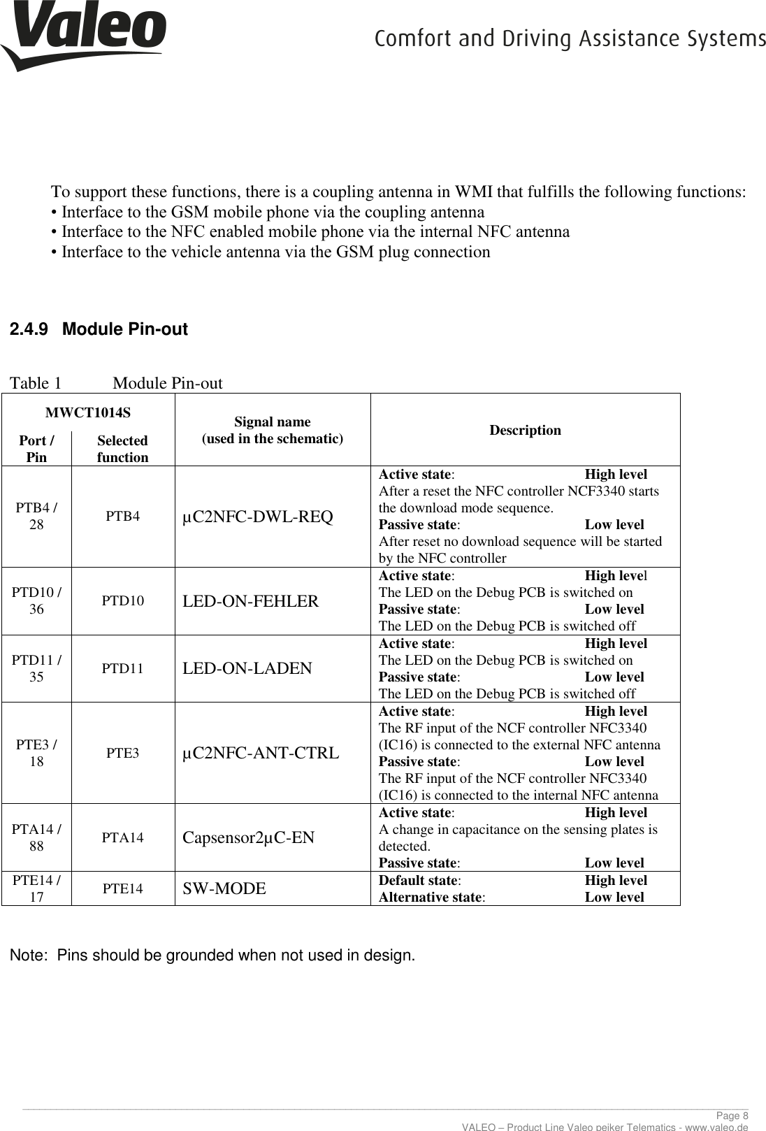
![________________________________________________________________________________________________________________________________ Page 17 VALEO – Product Line Valeo peiker Telematics - www.valeo.de 2.8 OPERATING MODES The system controller of the SBC manages register configuration and controls the internal functions. The system controller is a state machine. The SBC operating modes and the state transitions are shown in Figure 2.8-1. A detailed hardware characterization of the SBC operating modes by functional block is listed in the following Table 2.8-1 [1.] Determined by the setting of bits V2C in the regulator control register [2.] HVIO availability depends on the device variant [3.] Determined by the settings in the relevant HVIO control register [4.] See data sheet of the UJA1131HW/3V3, Fehler! Verweisquelle konnte nicht gefunden werden., section 7.10.4 [5.] Determined by the settings in the SMPS control register [6.] Determined by the setting of bits CMC in the CAN control register [7.] Availability of LIN2 depends on the device variant [8.] Determined by the setting of bits LMCn in the LIN control register [9.] Determined by the settings of bits ENC and ENDC in the fail-safe control register [10.] Since V1 is off, EN can only operate as open-drain output in Sleep mode [11.] Determined by the setting of bit LHC in the Fail-safe control register](https://usermanual.wiki/VALEO-Telematik-und-Akustik/WMI2W167.Users-Manual/User-Guide-3720126-Page-17.png)
![________________________________________________________________________________________________________________________________ Page 18 VALEO – Product Line Valeo peiker Telematics - www.valeo.de [12.] Determined by the setting of bits WMC in the Watchdog control register Table 2.8-1: Hardware characterization by functional block Figure 2.8-1: Operating modes of the System Basis Chip UJA1131HW/3V3 Via SPI2 interface the MWCT1014S is able to sent commands to the SBC so that the SBC can change the operating mode. The operating mode is selected via bits MC in the Mode Control register, see Table 2.8-2. SPI address of the Mode Control register: 0x01 Table 2.8-2: Mode Control register](https://usermanual.wiki/VALEO-Telematik-und-Akustik/WMI2W167.Users-Manual/User-Guide-3720126-Page-18.png)