VENTAHOOD Range Hood Manual L0709186
User Manual: VENTAHOOD VENTAHOOD Range Hood Manual VENTAHOOD Range Hood Owner's Manual, VENTAHOOD Range Hood installation guides
Open the PDF directly: View PDF ![]() .
.
Page Count: 7
Read and Save These Instructions
All Hoods Must Be Installed By A Qualified Installer
INSTALLATION INSTRUCTIONS
CWLH9 WALL MOUNT HOOD
Read All Instructions Thoroughly Before Beginning Installation
WARNING - TO REDUCE THE RISK OF FIRE, ELECTRIC SHOCK,
OR INJURY TO PERSONS, OBSERVE THE FOLLOWING:
A. Installation work and electrical wiring must be done by
qualified person(s) in accordance with all applicable codes and
standards, including fire-rated construction. Switch power off at
service panel and lock the service disconnecting means to
prevent power from being switched on accidentally during
installation.
B. When cutting or drilling into wall or ceiling, do not damage
electrical wiring and other hidden utilities.
C. Ducted fans must always be vented to the outdoors.
D. Sufficient air is needed for proper combustion and exhausting
of gases through the flue (chimney) of fuel burning equipment to
prevent back drafting. Follow the heating equipment
manufacturer's guideline and safety standards such as those
published by the National Fire Protection Association (NFPA), and
the American Society for Heating, Refrigeration and Air
Conditioning Engineers (ASHRAE), and local code authorities.
WARNING - TO REDUCE THE RISK OF FIRE, USE ONLY METAL
DUCTWORK
Page 1
(Rev. 04/07)
Ducting Do's and Don'ts
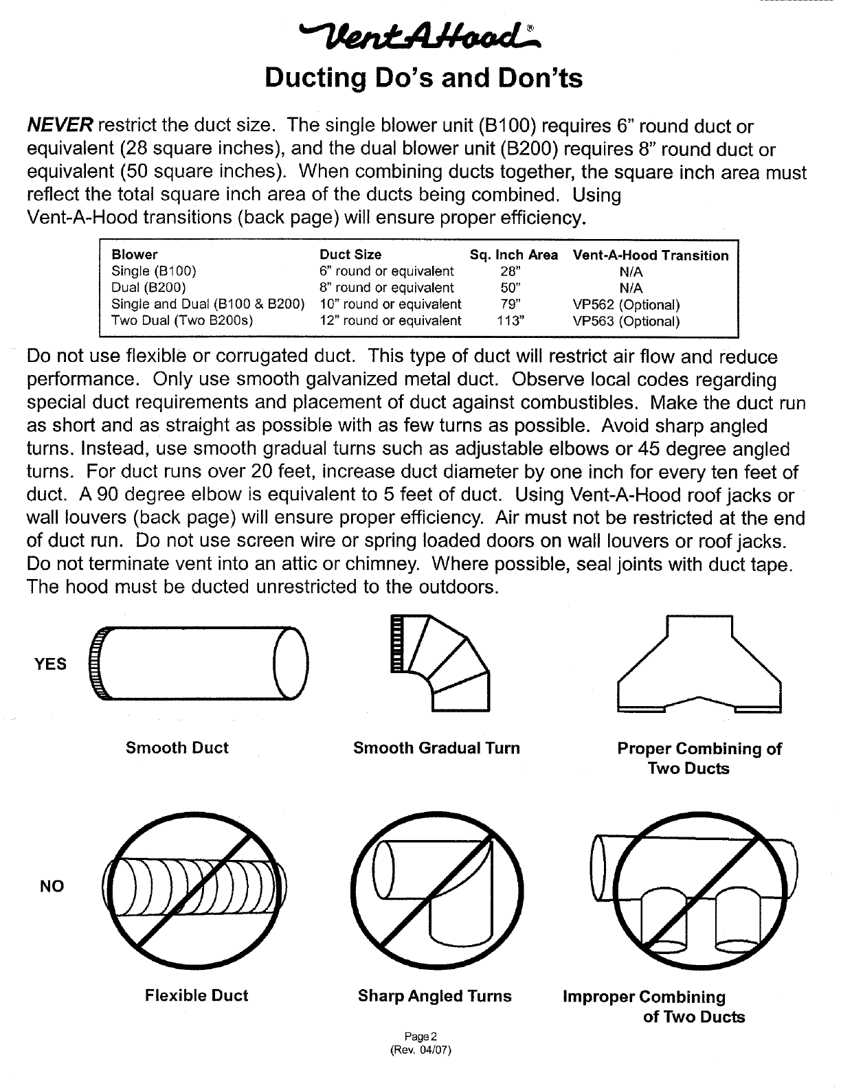
NEVER restrict the duct size. The single blower unit (B100) requires 6" round duct or
equivalent (28 square inches), and the dual blower unit (B200) requires 8" round duct or
equivalent (50 square inches). When combining ducts together, the square inch area must
reflect the total square inch area of the ducts being combined. Using
Vent-A-Hood transitions (back page) will ensure proper efficiency.
Blower
Single (B100)
Dual (B200)
Single and Dual (B100 & B200)
Two Dual (Two B200s)
Duct Size Sq. Inch Area
6" round or equivalent 28"
8" round or equivalent 50"
10" round or equivalent 79"
12" round or equivalent 113"
Vent-A-Hood Transition
N/A
N/A
VP562 (Optional)
VP563 (Optional)
Do not use flexible or corrugated duct. This type of duct will restrict air flow and reduce
performance. Only use smooth galvanized metal duct. Observe local codes regarding
special duct requirements and placement of duct against combustibles. Make the duct run
as short and as straight as possible with as few turns as possible. Avoid sharp angled
turns. Instead, use smooth gradual turns such as adjustable elbows or 45 degree angled
turns. For duct runs over 20 feet, increase duct diameter by one inch for every ten feet of
duct. A 90 degree elbow is equivalent to 5 feet of duct. Using Vent-A-Hood roof jacks or
wall louvers (back page) will ensure proper efficiency. Air must not be restricted at the end
of duct run. Do not use screen wire or spring loaded doors on wall louvers or roof jacks.
Do not terminate vent into an attic or chimney. Where possible, seal joints with duct tape.
The hood must be ducted unrestricted to the outdoors.
II
Smooth Duct Smooth Gradual Turn Proper Combining of
Two Ducts
NO
Flexible Duct Sharp Angled Turns
Page2
(Rev. 04/07)
Improper Combining
of Two Ducts
1)
2)
3)
4)
Installation Details
Read all instructions thoroughly before beginning installation.
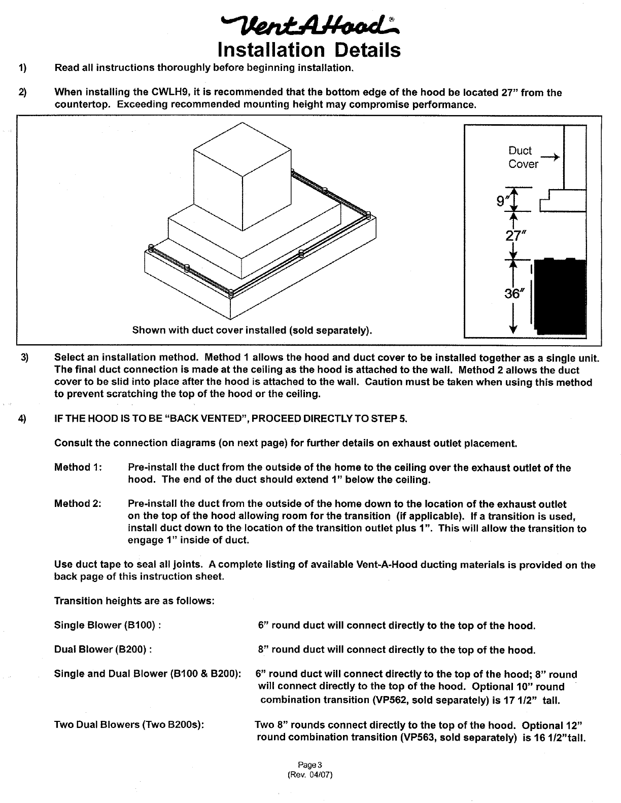
When installing the CWLH9, it is recommended that the bottom edge of the hood be located 27" from the
countertop. Exceeding recommended mounting height may compromise performance.
Shown with duct cover installed (sold separately).
Duct _ I
Cover "1
27"
Select an installation method. Method 1 allows the hood and duct cover to be installed together as a single unit.
The final duct connection is made at the ceiling as the hood is attached to the wall. Method 2 allows the duct
cover to be slid into place after the hood is attached to the wall. Caution must be taken when using this method
to prevent scratching the top of the hood or the ceiling.
IF THE HOOD IS TO BE "BACK VENTED", PROCEED DIRECTLY TO STEP 5.
Consult the connection diagrams (on next page) for further details on exhaust outlet placement.
Method 1: Pre.install the duct from the outside of the home to the ceiling over the exhaust outlet of the
hood. The end of the duct should extend 1" below the ceiling.
Method 2: Pre-install the duct from the outside of the home down to the location of the exhaust outlet
on the top of the hood allowing room for the transition (if applicable). If a transition is used,
install duct down to the location of the transition outlet plus 1". This will allow the transition to
engage 1" inside of duct.
Use duct tape to seal all joints. A complete listing of available Vent-A-Hood ducting materials is provided on the
back page of this instruction sheet.
Transition heights are as follows:
Single Blower (B100) :
Dual Blower (B200) :
Single and Dual Blower (B100 & B200):
Two Dual Blowers (Two B200s):
6" round duct will connect directly to the top of the hood.
8" round duct will connect directly to the top of the hood.
6" round duct will connect directly to the top of the hood; 8" round
will connect directly to the top of the hood. Optional 10" round
combination transition (VP562, sold separately) is 17 1/2" tall.
Two 8" rounds connect directly to the top of the hood. Optional 12"
round combination transition (VP563, sold separately) is 16 1/2"tall.
Page 3
(Rev. 04/07)
5)
6)
Installation Details Continued
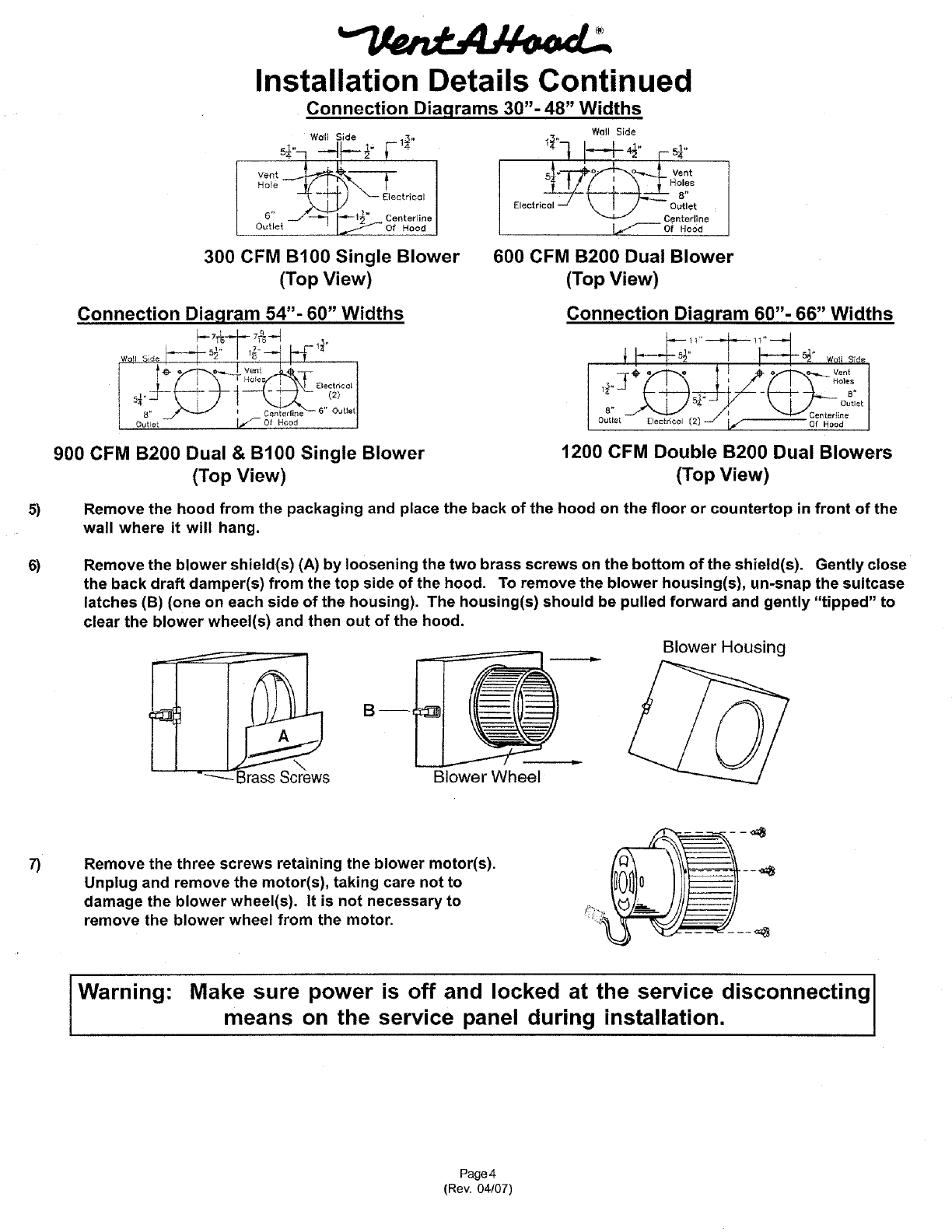
Connection Diaqrams 30"- 48" Widths
_" J-_ I---i_"Coote,-li°o=
O_,e_ I.__-°f_°°_I
300 CFM B100 Single Blower
(Top View)
Walt Side
5"Vent
600 CFM B200 Dual Blower
(Top View)
Connection Diagram 54"- 60" Widths
_5 _" l 1?''--'J I_ I-" ;_
]IHole _} Klect ricel
900 CFM B200 Dual & B100 Single Blower
(Top View)
Connection Diagram 60"- 66" Widths
. at
J_ j I/_Centerine
Outlet Electr;¢ol (2) If" Of Hood
1200 CFM Double B200 Dual Blowers
(Top View)
Remove the hood from the packaging and place the back of the hood on the floor or countertop in front of the
wall where it will hang.
Remove the blower shield(s) (A) by loosening the two brass screws on the bottom of the shield(s). Gently close
the back draft damper(s) from the top side of the hood. To remove the blower housing(s), un-snap the suitcase
latches (B) (one on each side of the housing). The housing(s) should be pulled forward and gently "tipped" to
clear the blower wheel(s) and then out of the hood.
Bin.
Blower Wheel
Blower Housing
7) Remove the three screws retaining the blower motor(s).
Unplug and remove the motor(s), taking care not to
damage the blower wheel(s). It is not necessary to
remove the blower wheel from the motor.
Warning: Make sure power is off and locked at the service disconnecting
means on the service panel during installation.
Page 4
(Rev. 04/07)
8)
9)
10)
11)
12)
13)
14)
Installation Details Continued
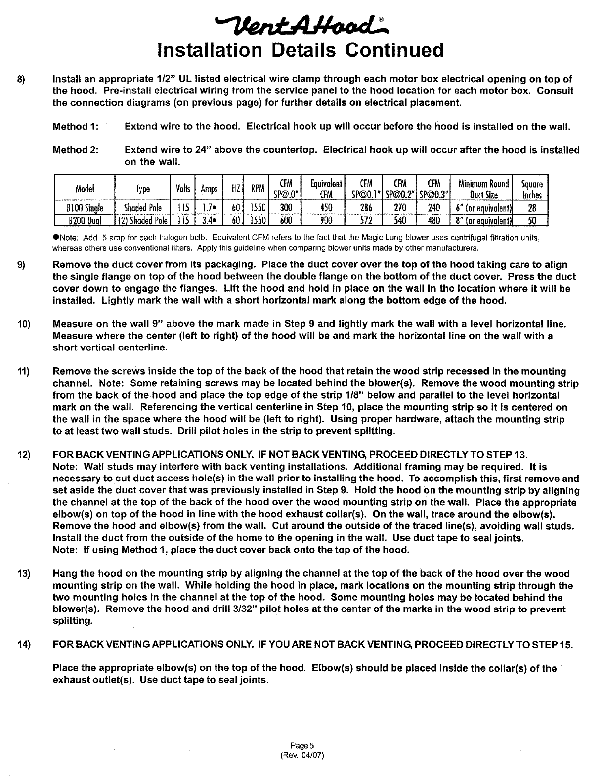
Install an appropriate 1/2" UL listed electrical wire clamp through each motor box electrical opening on top of
the hood. Pre-install electrical wiring from the service panel to the hood location for each motor box. Consult
the connection diagrams (on previous page) for further details on electrical placement.
Method 1: Extend wire to the hood. Electrical hook up will occur before the hood is installed on the wall.
Method 2: Extend wire to 24" above the countertop. Electrical hook up will occur after the hood is installed
on the wall.
Model Type Volts Amps HZ RPM CFM Equivalent CFM CFM CFM MinimumRound Square
SP@.O" CFM SP@0.1"SP@0.2"SP@0.3" DuctSize Inches
BIO0Single ShadedPole t15 1.7. 60 1550 300 450 286 270 240 6"(orequivalent] 28
B200Dual (2)ShadedPule 115 3.4* 60 1550 600 900 572 540 480 8"(orequivalenl] 50
QNote: Add .5 amp for each halogen bulb. Equivalent CFM refers to the fact that the Magic Lung blower uses centrifugal filtration units,
whereas others use conventional filters. Apply this guideline when comparing blower units made by other manufacturers.
Remove the duct cover from its packaging. Place the duct cover over the top of the hood taking care to align
the single flange on top of the hood between the double flange on the bottom of the duct cover. Press the duct
cover down to engage the flanges. Lift the hood and hold in place on the wall in the location where it will be
installed. Lightly mark the wall with a short horizontal mark along the bottom edge of the hood.
Measure on the wall 9" above the mark made in Step 9 and lightly mark the wall with a level horizontal line.
Measure where the center (left to right) of the hood will be and mark the horizontal line on the wall with a
short vertical centerline.
Remove the screws inside the top of the back of the hood that retain the wood strip recessed in the mounting
channel. Note: Some retaining screws may be located behind the blower(s). Remove the wood mounting strip
from the back of the hood and place the top edge of the strip 1/8" below and parallel to the level horizontal
mark on the wall. Referencing the vertical centerline in Step 10, place the mounting strip so it is centered on
the wall in the space where the hood will be (left to right). Using proper hardware, attach the mounting strip
to at least two wall studs. Drill pilot holes in the strip to prevent splitting.
FOR BACK VENTING APPLICATIONS ONLY. IF NOT BACK VENTING, PROCEED DIRECTLY TO STEP 13.
Note: Wall studs may interfere with back venting installations. Additional framing may be required. It is
necessary to cut duct access hole(s) in the wall prior to installing the hood. To accomplish this, first remove and
set aside the duct cover that was previously installed in Step 9. Hold the hood on the mounting strip by aligning
the channel at the top of the back of the hood over the wood mounting strip on the wall. Place the appropriate
elbow(s) on top of the hood in line with the hood exhaust collar(s). On the wall, trace around the elbow(s).
Remove the hood and elbow(s) from the wall. Cut around the outside of the traced line(s), avoiding wall studs.
Install the duct from the outside of the home to the opening in the wall. Use duct tape to seal joints.
Note: If using Method 1, place the duct cover back onto the top of the hood.
Hang the hood on the mounting strip by aligning the channel at the top of the back of the hood over the wood
mounting strip on the wall. While holding the hood in place, mark locations on the mounting strip through the
two mounting holes in the channel at the top of the hood. Some mounting holes may be located behind the
blower(s). Remove the hood and drill 3/32" pilot holes at the center of the marks in the wood strip to prevent
splitting.
FOR BACK VENTING APPLICATIONS ONLY. IF YOU ARE NOT BACK VENTING, PROCEED DIRECTLY TO STEP 15.
Place the appropriate elbow(s) on the top of the hood. Elbow(s) should be placed inside the collar(s) of the
exhaust outlet(s). Use duct tape to seal joints.
Page 5
(Rev. 04/07)
14)
Installation Details Continued
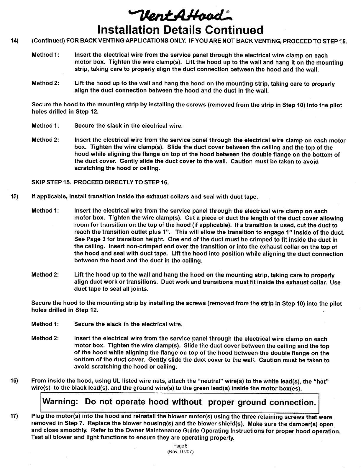
(Continued) FOR BACK VENTING APPLICATIONS ONLY. IF YOU ARE NOT BACK VENTING, PROCEED TO STEP 15.
Method 1: Insert the electrical wire from the service panel through the electrical wire clamp on each
motor box. Tighten the wire clamp(s). Lift the hood up to the wall and hang it on the mounting
strip, taking care to properly align the duct connection between the hood and the wall.
Method 2: Lift the hood up to the wall and hang the hood on the mounting strip, taking care to properly
align the duct connection between the hood and the duct in the wall.
Secure the hood to the mounting strip by installing the screws (removed from the strip in Step 10) into the pilot
holes drilled in Step 12.
Method t: Secure the slack in the electrical wire.
Method 2: Insert the electrical wire from the service panel through the electrical wire clamp on each motor
box. Tighten the wire clamp(s). Slide the duct cover between the ceiling and the top of the
hood while aligning the flange on top of the hood between the double flange on the bottom of
the duct cover. Gently slide the duct cover to the wall. Caution must be taken to avoid
scratching the hood or ceiling.
SKIP STEP 15. PROCEED DIRECTLY TO STEP 16.
15) If applicable, install transition inside the exhaust collars and seal with duct tape.
Method 1: Insert the electrical wire from the service panel through the electrical wire clamp on each
motor box. Tighten the wire clamp(s). Cut a piece of duct the length of the duct cover allowing
room for transition on the top of the hood (if applicable). If a transition is used, cut the duct to
reach the transition outlet plus 1". This will allow the transition to engage 1" inside of the duct,
See Page 3 for transition height. One end of the duct must be crimped to fit inside the duct in
the ceiling. Insert non-crimped end over the transition or into the exhaust collar on the top of
the hood and seal with duct tape. Lift the hood into position while aligning the duct connection
between the hood and the duct in the ceiling.
Method 2: Lift the hood up to the wall and hang the hood on the mounting strip, taking care to properly
align duct work or transitions. Duct work and transitions must fit inside the exhaust collar. Use
duct tape to seal all joints.
Secure the hood to the mounting strip by installing the screws (removed from the strip in Step 10) into the pilot
holes drilled in Step 12.
Method 1: Secure the slack in the electrical wire.
Method 2: Insert the electrical wire from the service panel through the electrical wire clamp on each
motor box. Tighten the wire clamp(s). Slide the duct cover between the ceiling and the top
of the hood while aligning the flange on top of the hood between the double flange on the
bottom of the duct cover. Gently slide the duct cover to the wall. Caution must be taken to
avoid scratching the hood or ceiling.
16)
17)
From inside the hood, using UL listed wire nuts, attach the "neutral" wire(s) to the white lead(s), the "hot"
wire(s) to the black lead(s), and the ground wire(s) to the green lead(s) inside the motor box(es).
Warning: Do not operate hood without proper ground connection,
Plug the motor(s) into the hood and reinstall the blower motor(s) using the three retaining screws that were
removed in Step 7. Replace the blower housing(s) and the blower shield(s). Make sure the damper(s) open
and close smoothly. Refer to the Owner Maintenance Guide Operating Instructions for proper hood operation.
Test all blower and light functions to ensure they are operating properly.
Page 6
(Rev. 07/07)
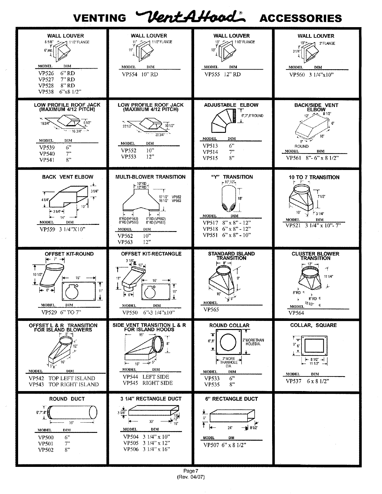
VENTING ACCESSORIES
WALL LOUVER
8 5/_'_1112" FLANGE
MODEl, DIM
VP526 6" RD
VP527 7" RD
VP528 8" RD
VP538 6"x8 1/2"
LOW PROFILE ROOF JACK
(MAXIMUM 4112 PITCH)
_ 16314 °
WALL LOUVER
11_x._ 1/2"FLANGE
MODEl, DIM
VP554 10" RD
LOW PROFILE ROOF JACK
(MAXIMUM 4/12 PITCH)
WALL LOUVER
13LLL
MODEL DIM
VP555 12" RD
ADJUSTABLE ELBOW
[_ _6__6",7",8"ROUND
WALL LOUVER
_!_ 2"FLANGE
31! LL
MODEL DIM
VP560 3 l/4"x10"
MODEL OhM
VP539 6"
VP540 7"
VP54I 8"
BACK VENT ELBOW
-'F
10"4
_- 3114'-_ ¢
_- !4 °
MODEL DIM
VP552 10"
VP553 12"
MULTI-BLOWER TRANSITION
10"RD
_12"RD_
171/2" VP562
"VP563
4 _ 4
MODEL DIM
VP513 6"
VP514 7"
VP515 8"
MODEL
"Y" TRANSITION
10"12_
_,
I
18"
DIM
BACK/SIDE VENT
ELBOW
12' _*" 61/2"
NOUND
MODEL DIM
VP561 8"- 6" x 8 1/2"
10 TO 7 TRANSITION
1t2"
,14•
MODEL DIM
MODEL DIM
VP559 3 l/4"X]0"
OFFSET KIT-ROUND
rN
101,y •+
11"
. • 3_
MODEL DIM
VP529 6" TO 7"
OFFSET L & R TRANSITION
FOR ISLAND BLOWERS
12"
9"
DIMMODEL
VP542 TOP LEFTISLAND
VP543 TOP RIGHT ISLAND
ROUND DUCT
MODEL DIM
VP500 6"
VP501 7"
VP502 8"
8'=RD P562
8. RD((VP5631 6"RD VP562
MODEL Dffvl
VP562 !0"
VP563 12"
OFFSET KIT-RECTANGLE
3114]_
1,__ "t 1o°,1
11"__ 16"
L•
MODEL DIM
VP550 6"-3 !i4"x10"
SIDE VENT TRANSITION L & R
FOR ISLAND HOODS
_- 16" --"F 5"
MODEL DIM
VP544 LEFT SIDE
VP545 RIGHT SIDE
3 114" RECTANGLE DUCT
%1
MODEL DIM
"vT504 3 1/4"x 10"
VP505 3 1/4"x 12"
VP506 3 1/4"x 16"
VP517 8" x 8" - 12"
VPS18 6" x 8"- 12"
VP551 6"x 8"- 10"
STANDARD ISLAND
TRANSITION
9"
MODEL
VP565
ROUND COLLAR
-©
6",8" 2"MORETHAN
HOLEDIA.
3r_ ,_.L
L,_rMOREJ
/THANHOLE -1
DIA
MODEL DIM
VP533 6"
VP535 8"
6" RECTANGLE DUCT
MODEL DIM
VP507 6" x 8 1/2"
VP521 3 1/4" x 10"- 7"
CLUSTER BLOWER
TRANSITION
F12"_
111!4"
F8"RD '1
MODEL 181/2_ d
VP564
COLLAR, SQUARE
"I---]"
9"6,,
__F81!r41
11112" -_4
MODEL DIM
VP537 6x81/2"
Page 7
(Rev. 04/07)
