VIA Technologies VNT6656GEV0X 802.11 BG Wireless Module User Manual
VIA Technologies, Inc. 802.11 BG Wireless Module
Contents
- 1. Users Manual
- 2. OEM Installation Manual
- 3. User Manual
User Manual

VNT6656GEV00
USER'S MANUAL
Revision 1.0
June 6, 2006
VIA TECHNOLOGIES, INC.

Copyright Notice:
Copyright © 2006, VIA Technologies, Incorporated. All Rights Reserved.
No part of this document may be reproduced, transmitted, transcribed, stored in a retrieval
system, or translated into any language, in any form or by any means, electronic, mechanical,
magnetic, optical, chemical, manual or otherwise without the prior written permission of VIA
Technologies, Incorporated.
VNT6656GEV00 may only be used to identify WLAN products of VIA Technologies, Inc.
is a registered trademark of VIA Technologies, Incorporated.
All trademarks are the properties of their respective owners.
Disclaimer Notice:
No license is granted, implied or otherwise, under any patent or patent rights of VIA
Technologies Inc. VIA Technologies Inc. makes no warranties, implied or otherwise, in
regard to this document and to the products described in this document. The information
provided by this document is believed to be accurate and reliable as of the publication date
of this document. However, VIA Technologies Inc. assumes no responsibility for any errors in
this document. Furthermore, VIA Technologies Inc. assumes no responsibility for the use or
misuse of the information in this document and for any patent infringements that may arise
from the use of this document. The information and product specifications within this
document are subject to change at any time, without notice and without obligation to notify
any person of such change.
Offices:
USA Office: Taipei Office:
940 Mission Court 8th Floor, No. 533
Fremont, CA 94539 Chung-Cheng Road, Hsin-Tien
USA Taipei, Taiwan ROC
Tel: (510) 683-3300 Tel: (886-2) 2218-2078
Fax: (510) 683-3301 or (510) 687-4654 Fax: (886-2) 2219-8461
Web: www.vntek.com Web: www.vntek.com.tw

VIA Technologies, Inc. User's Manual
Revision 1.0 • June 6, 2006 - iii - Revision History
Revision History
Release Date Revision Initials
1.0 2006-06-06 Initial release. SH

VIA Technologies, Inc. User's Manual
Revision 1.0 • June 6, 2006 - iv - Table of Contents
Table of Contents
1. Features........................................................................................................................1
1.1. Drivers and Applications.......................................................................................... 1
1.2. Certifications ........................................................................................................... 1
1.3. Software Packages ................................................................................................. 1
1.4. Programming Guide ................................................................................................ 1
2. Drivers and Utilities..................................................................................................... 2
2.1. Drivers..................................................................................................................... 2
2.2. Utilities for end users............................................................................................... 2
2.3. Utilities for manufacturers........................................................................................ 2
3. Software Package Information ................................................................................... 3
3.1. Directory structure................................................................................................... 3
3.2. Driver Keywords/Parameters .................................................................................. 4
4. Windows Utilities......................................................................................................... 6
4.1. WiFiset .................................................................................................................... 6
4.1.1. Status................................................................................................................... 6
4.1.2. Config................................................................................................................... 6
4.1.3. Site Survey......................................................................................................... 10
4.1.4. Statistics............................................................................................................. 11
4.1.5. Signal................................................................................................................. 11
4.1.6. Profiles............................................................................................................... 12
4.2. WPA Networking ................................................................................................... 16
Appendix A: Terminology................................................................................................... 19
Appendix B: Important Notices.......................................................................................... 20

For OEM integrators
This device is intended only for OEM integrators under the following conditions:
1) The antenna must be installed such that 20 cm is maintained between the
antenna and users, and
2) The transmitter module may not be co-located with any other transmitter or
antenna.
As long as the 2 conditions above are met, further transmitter testing will not be
required. However, the OEM integrator is still responsible for testing their
end-product for any additional compliance requirements required with this module
installed (for example, digital device emissions, PC peripheral requirements, etc.).
IMPORTANT NOTE: In the event that these conditions can not be met (for
example certain laptop configurations or co-location with another transmitter),
then the FCC authorization is no longer considered valid and the FCC ID can not
be used on the final product. In these circumstances, the OEM integrator will be
responsible for re-evaluating the end product (including the transmitter) and
obtaining a separate FCC authorization.
End Product Labeling
This transmitter module is authorized only for use in devices where the antenna
may be installed such that 20 cm may be maintained between the antenna and
users (for example Notebook PC, access points, routers, wireless ASDL modems,
and similar equipment). The final end product must be labeled in a visible area
with the following: "Contains TX FCC ID: NCI-VNT6656GEV0X".
.
Manual Information That Must be Included
The users manual for end users must include the following information in a
prominent location "IMPORTANT NOTE: To comply with FCC RF exposure
compliance requirements, the antenna used for this transmitter must be installed to
provide a separation distance of at least 20 cm from all persons and must not be
co-located or operating in conjunction with any other antenna or transmitter."
Additional Information That Must be Provided to OEM Integrators
The end user should NOT be provided any instructions on how to remove or
install the device.
The module is for OEM installation only and can not be sold to end user directly.
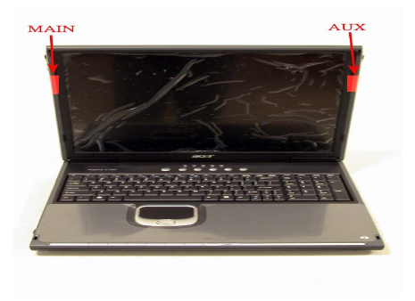
Hardware Installation & Antenna Information
z MODULE IS INSTALLED IN THE PERSONAL COMPUTER, LOCATED ON THE
BOTTOM SIDE OF THE PERSONAL COMPUTER.
z Antennas are embedded in the two sides (see the two antennas shown
below)
Only the antenna types listed below can be used:
Antenna 1: PIFA (6-23-7M59K-021, made by FAVORTRON CO., LTD)
Antenna 2: PIFA (6-23-7M59K-011, made by FAVORTRON CO., LTD)
Antenna 3: PIFA (13-130-F14911, made by VSO ELECTRIC CO., LTD )
Antenna 4: PIFA (13-130-F14931, made by VSO ELECTRIC CO., LTD)
Antenna 5: PIFA (13-130-F53021, made by VSO ELECTRIC CO., LTD)
Antenna 6: PIFA (13-130-F62011, made by VSO ELECTRIC CO., LTD)
Antenna 7: PIFA (13-130-F62021, made by VSO ELECTRIC CO., LTD)
Antenna 8: PIFA (14-211-F66021, made by VSO ELECTRIC CO., LTD)
Antenna 9: PIFA (14-211-F66041, made by VSO ELECTRIC CO., LTD)
Antenna 10: PIFA (K05008004451, made by FAVORTRON CO., LTD)
Antenna 11: PIFA (K05008004351, made by FAVORTRON CO., LTD)
Antenna 12: PIFA (K05008003651, made by FAVORTRON CO., LTD)
Antenna 13: PIFA (K05008003751, made by FAVORTRON CO., LTD)
Antenna 14: PIFA (K05004002251, made by FAVORTRON CO., LTD)
Antenna 15: PIFA (K05004002351, made by FAVORTRON CO., LTD)
Antenna 16: PIFA (WDAN-U1L41001-DF, made by Hon Hai Precision Industry Co.,Ltd.)
Antenna 17: PIFA (WDAN -U1L51002 -DF, made by Hon Hai Precision Industry Co.,Ltd.)
Antenna 18: PIFA (H12V-R, H12V-L, Well Green Technology Co., Ltd)
Antenna 19: PIFA (S14Y-R, S14Y-L, Well Green Technology Co., Ltd)
Antenna 20: PIFA (S-37, Tyco Electronics)
Antenna 21: PIFA (M73XT, FAVORTRON CO., LTD)
Antenna 22: PIFA (M76XT, FAVORTRON CO., LTD)
Antenna 23: PIFA (6-23-7M54S-010, FAVORTRON CO., LTD)
Important Note:
This module is restricted to mobile configuration. The antennas of module
should be installed and operated with minimum distance 20cm between the
radiator and all persons. This transmitter must not be co-located or operating in
conjunction with any other antenna or transmitter.
The module is for OEM installation only and can not be sold to end user directly.
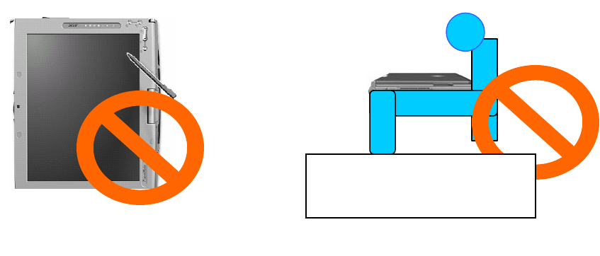
*Caution !!
(1). This module cannot be bound in a tablet computer for RF exposure issues.
(See label 1)
(2). Due to the RF exposure issues, this module can be used in a laptop computer
in normal operation, but cannot be used when it is put above the lap and the
LCD screen is in the closed position. (See label 2)
Label 1 Label 2
The device can’t be operated above
the lap when the LCD is closed
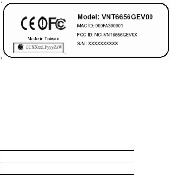
(3). This module must be labeled with FCC ID. (See label 3)
(4). If the FCC ID is not visible when the module is installed inside another
device, then the outside of device must also display a label referring to the
enclosed module. The exterior label can be
“ Contains Transmitter Module FCC ID: NCI-VNT6656GEV0X” or similar
wording. (See label 4)
Contains Transmitter Module VNT6656GEV00
FCC ID: NCI-VNT6656GEV0X
Please put Label 3 & Label 4 to the enclosure of end product to note the end user.
Label 3
Label 4

VIA Technologies, Inc. User's Manual
Revision 1.0 • June 6, 2006 - 1 - Features
1. Features
1.1. Drivers and Applications
Drivers available for Microsoft Windows 98/ME/NT/2000/XP and all major distributions
of Linux.
Setup utility for automatic driver installation on Windows.
Mass-production support tool.
Mass-production application interface for custom programs.
PATCH utility for driver customization. This utility allows the manufacturers to customize
the driver packages, such as changing the drivers’ icons and file names.
1.2. Certifications
"Designed for Microsoft Windows" Logo.
Wi-Fi Certified.
1.3. Software Packages
Software package for manufacturers: A complete set of drivers and utilities.
Evaluation package (CD version) for manufacturers: Includes MPTOOL, Winsetup, and
drivers for Windows only.
Software package for end users: Includes all drivers and utilities, except MPTOOL and
PATCH.
1.4. Programming Guide
All drivers are available in the binary format. Source codes are not released.
An EEPROM layout guide is available.
VIA Technologies, Inc. User's Manual
Revision 1.0 • June 6, 2006 - 2 - Drivers and Utilities
2. Drivers and Utilities
2.1. Drivers
DRIVER TYPE DESCRIPTION
NDIS 5 Supports Windows SE, ME, 2000, XP, XPe, and Sever 2003.
NDIS 4 Supports Windows NT 4.0.
WinCE 4.2 Supports Windows CE 4.2.
WinCE 5 Supports Windows CE 5.0.
x64 Supports AMD 64-bit CPUs.
2.2. Utilities for end users
UTILITY NAME DESCRIPTION
Winsetup Automatic driver installation, uninstallation, and updating utility for
Windows 98 SE, ME, NT 4.0, 2000, XP, and Sever 2003.
WiFiset Wireless configuration setup tool for Windows 98, 98 SE, ME, NT
4.0, 2000, XP, and Sever 2003.
2.3. Utilities for manufacturers
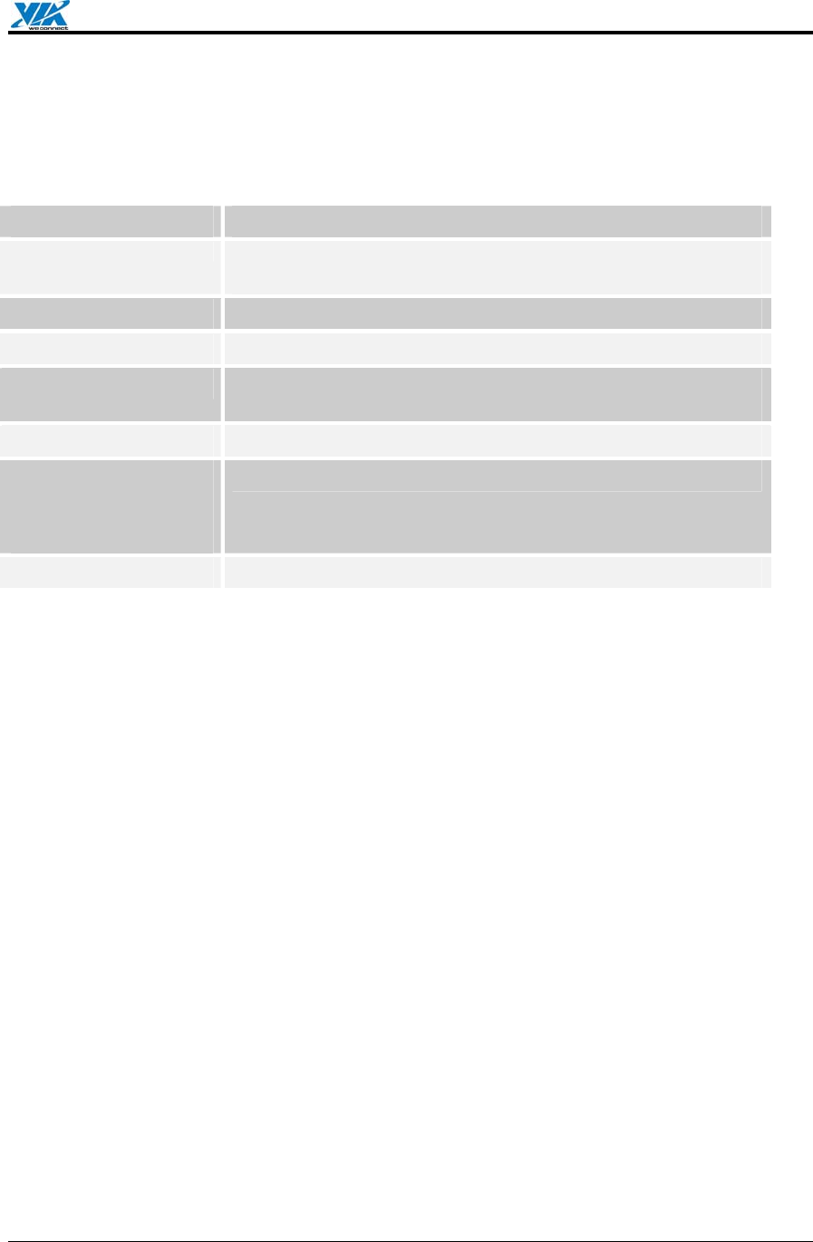
UTILITY TYPE DESCRIPTION
MPTOOL Mass-production tool for Windows 2000/XP.
MP API Mass-production application interface for manufacturer-specific
programs.
VIA Technologies, Inc. User's Manual
Revision 1.0 • June 6, 2006 - 3 - Software Package Information
3. Software Package Information
3.1. Directory structure
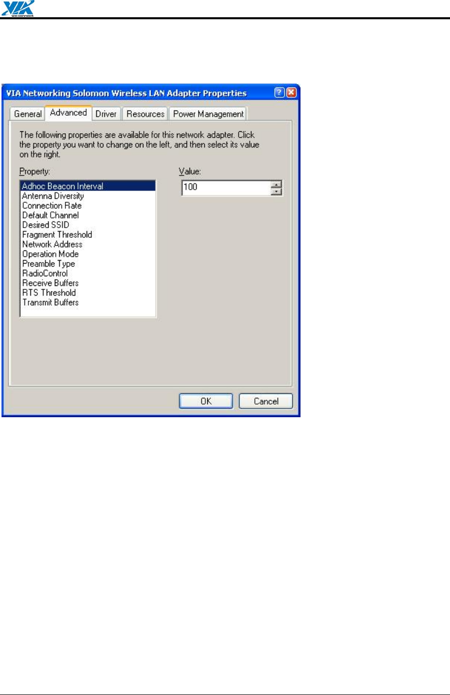
DIRECTORY DESCRIPTION
/ (Root directory) Drivers for Windows 98 SE, ME, NT 4.0, 2000, XP, and
Sever 2003; release note; and other documentations.
/XPe Driver for Windows XP Embedded.
/WIFISET Wireless configuration setup tool for Windows.
/WINSETUP Windows driver setup utility for Windows 98 SE, ME, NT 4.0,
2000, XP, and Sever 2003.
/MPTOOL Mass-production tool and the EEPROM layout guide.
/Win CE
/ CE4.2
/ CE5
Drivers for Windows CE 4.2 and 5.0.
/x64 Software for supporting AMD 64.
VIA Technologies, Inc. User's Manual
Revision 1.0 • June 6, 2006 - 4 - Software Package Information
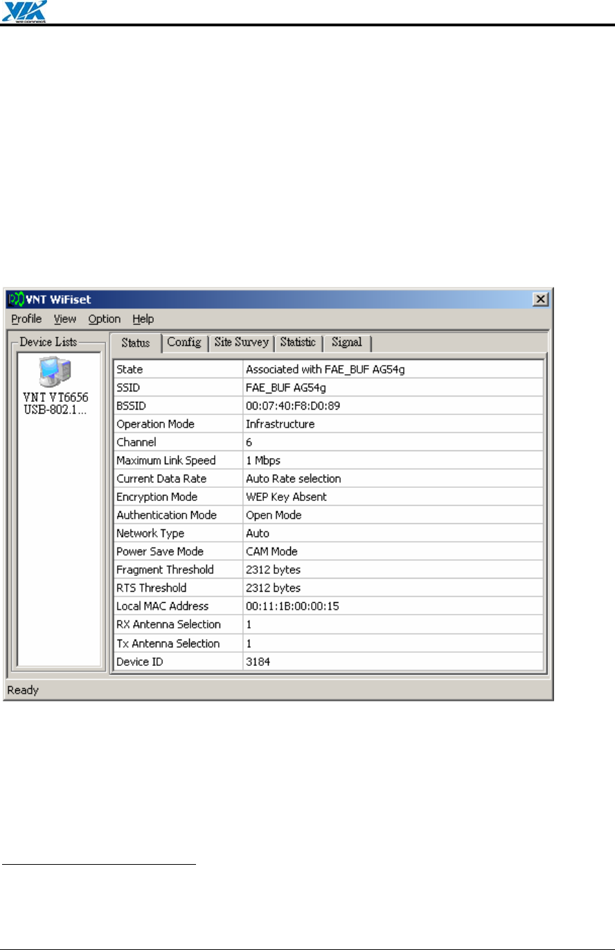
3.2. Driver Keywords/Parameters
Figure 1. Properties—Advanced
Adhoc Beacon Interval
Defines the beacon interval in the ad hoc mode.
Antenna Diversity
Enables or disables antenna diversity.
Connection Rate
Specifies the connection rate (in Mbps): 1, 2, 5.5, 11, 6, 9, 12, 18, 24, 36, 48, 54, or Auto.
Default Channel
The user-defined connection channel—applicable in the ad hoc mode and AP mode.
Desired SSID
The user-defined SSID—to be automatically connected at driver startup.
Fragment Threshold
Defines the size at which packets are fragmented.

VIA Technologies, Inc. User's Manual
Revision 1.0 • June 6, 2006 - 5 - Software Package Information
Network Address
The user-defined network address—overrides the network address originally set by the
hardware vendor.
Operation Mode
Determines the operation mode: Infrastructure or Ad Hoc.
Preamble Type
Determines the acceptable preamble type: Select Long to accept long preambles only;
select Short to support short preambles.
RadioControl
Determines whether the radio is on or off.
Receive Buffers
Defines the size of the internal driver buffers for received packets.
RTS Threshold
Defines the size at which packets are sent via the RTS-CTS mechanism.
Transmit Buffers
Defines the size of the internal driver buffers for packets to be transmitted.
VIA Technologies, Inc. User's Manual
Revision 1.0 • June 6, 2006 - 6 - Windows Utilities
4. Windows Utilities
4.1. WiFiset1
The VIA WiFiset is a Windows-based application. Its main features are listed below.
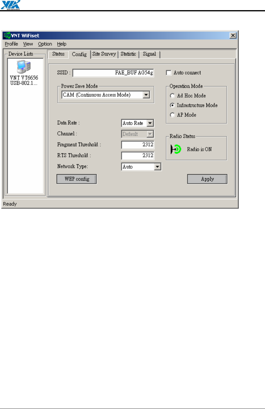
4.1.1. Status
Displays the network status of the device.
Figure 2. WiFiset—Status
4.1.2. Config
Displays and controls the link configurations for the device.
1 To avoid software conflict, WiFiset does not synchronize its settings with Windows Zero
Configuration (WZC), nor vice versa.
VIA Technologies, Inc. User's Manual
Revision 1.0 • June 6, 2006 - 7 - Windows Utilities
Figure 3. WiFiset—Config
SSID
The service set identifier (SSID) is the name given to a wireless network by its
administrator(s). The default value is Any, which allows the device to connect to any access
point in the Infrastructure Mode, or to any other wireless device in the Ad Hoc Mode. The
SSID can be up to 32 characters long, and is case sensitive.
Power Save Mode
Selects a power-save mode from three preconfigured settings:
• CAM (Continuous Access Mode) Highest performance with no power saving.
• Max PSP (Max Power Saving Mode) Maximum power saving with reduced
performance.
• Fast PSP (Fast Power Saving Mode) Greater power saving than CAM and higher
performance than Max PSP.
Operation Mode
Determines the type of network or mode of operation.
• Ad Hoc Mode For peer-to-peer networking with other wireless devices without routing
through wired network.
• Infrastructure Mode (default) For connecting to a wired network via an access point.
• AP Mode For setting up the device as an access point. Note: In order to function as an
access point, your computer must be physically connected to a wired network.

VIA Technologies, Inc. User's Manual
Revision 1.0 • June 6, 2006 - 8 - Windows Utilities
Radio Status
Shows whether the radio is on or off.
Data Rate
Selects the rate of transmission between your computer and the access point (in the
infrastructure mode) or another wireless device (in the ad hoc mode). In general, a higher
transmission rate would provide a smaller coverage area, and a lower transmission rate
would cover a greater distance. The default setting is Auto Rate, which allows the device to
start at 54 Mbps and automatically lowers the transmission rate when necessary.
Channel
Selects the frequency channel for the transmission in the Ad Hoc Mode or AP Mode.
Fragment Threshold
Defines the size at which packets are fragmented. The acceptable range of values is from
256 to 2312 bytes, and the default value is 2312 bytes.
RTS Threshold
Defines the size at which packets are sent via the RTS-CTS mechanism. The acceptable
range of values is from 0 to 2312 bytes, and the default value is 2312 bytes.
Network Type
Selects the 802.11 network protocol usage; there are three modes, “802.11b only”,
“802.11g”, and “Auto”. The default setting is Auto.
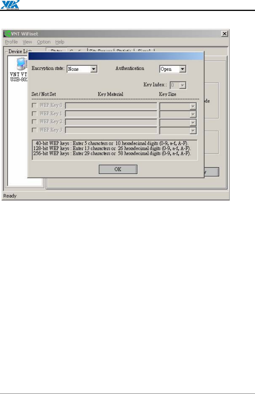
WEP config
Controls the authentication and encryption configurations for the device.
VIA Technologies, Inc. User's Manual
Revision 1.0 • June 6, 2006 - 9 - Windows Utilities
Figure 4. WiFiset—WEP config
Encryption state
Determines whether Wired Equivalent Privacy (WEP) is used for data encryption.
• None (default) No encryption.
• WEP Data is encrypted with a WEP key. Up to four WEP keys can be specified. Each
key can have a length of 40, 128, or 256 bits.
Authentication Mode
Determines the method of authentication.
• Open System (Default) A null authentication algorithm is used, which allows the device
to be authenticated by any access point or other devices with an appropriate SSID.
• Shared Key A WEP key is used as a means of authentication, which allows the device
to be authenticated only by access points or other devices that has the same WEP key in
addition to an appropriate SSID.
VIA Technologies, Inc. User's Manual
Revision 1.0 • June 6, 2006 - 10 - Windows Utilities
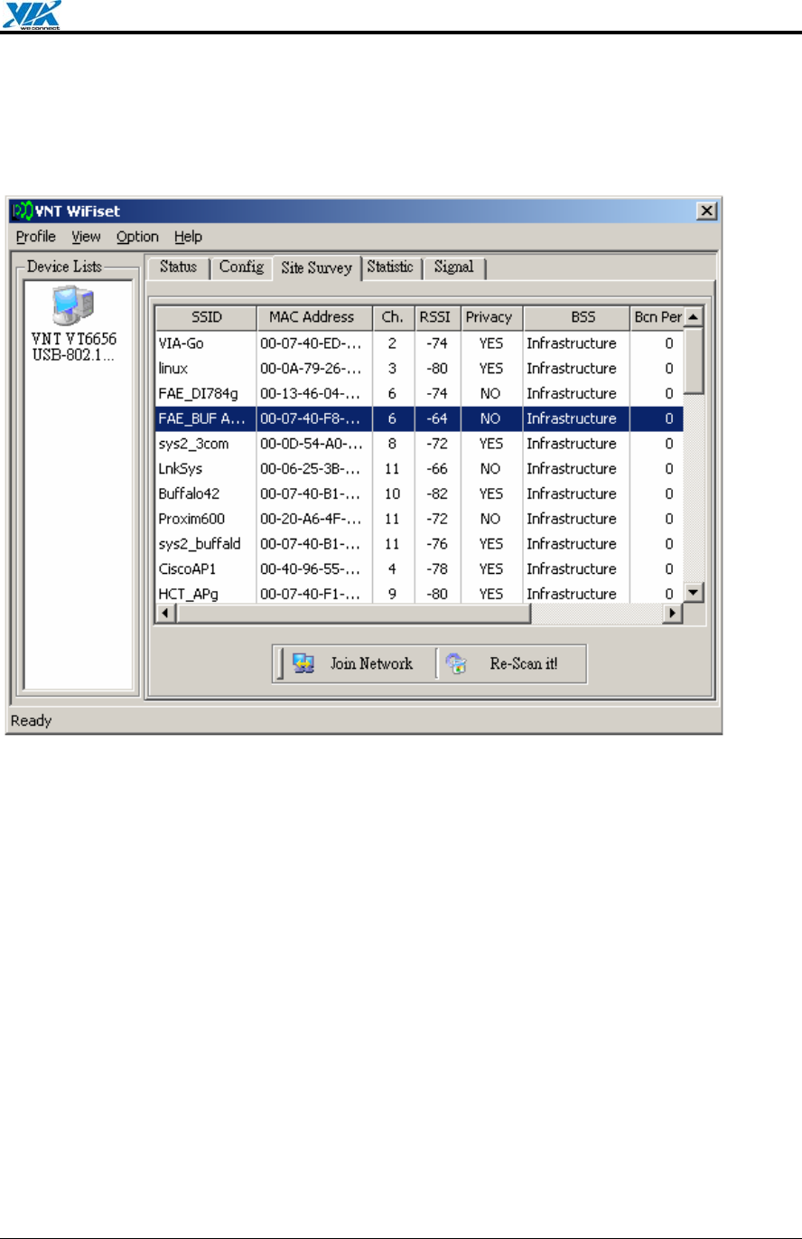
4.1.3. Site Survey
Displays a list of all available networks within range.
Figure 5. WiFiset—Site Survey
Join Network
Joins the device to the selected network.
Re-Scan it!
Re-scans to discover all currently available networks within range.
VIA Technologies, Inc. User's Manual
Revision 1.0 • June 6, 2006 - 11 - Windows Utilities
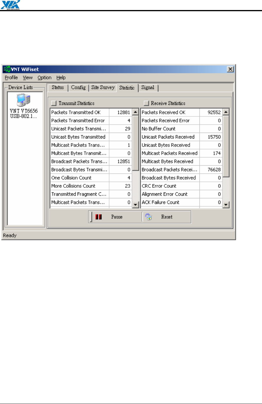
4.1.4. Statistics
Displays the real-time transmission and reception statistics of the device.
Figure 6. WiFiset—Statistic
Pause
Pauses, or freezes, the currently displayed statistics. Clicking Pause again will resume the
real-time display.
Reset
Resets all values to zero.
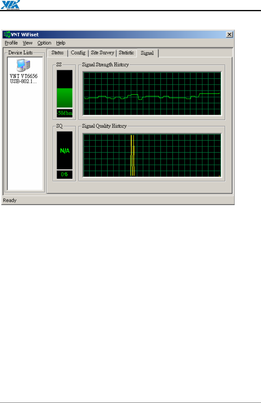
4.1.5. Signal
Displays the current and past values of signal strength (SS) and signal quality (SQ) for the
connected network.
VIA Technologies, Inc. User's Manual
Revision 1.0 • June 6, 2006 - 12 - Windows Utilities
Figure 7. WiFiset—Signal
4.1.6. Profiles
A profile is a set of preconfigured settings for a particular network environment. Having
different profiles stored in WiFiset, you can move from one network to another without having
to reconfigure the network settings.
4.1.6.1. Adding a new profile
Before adding the current network configuration as a new profile, make sure that your device
is connected to a network and that all settings are properly configured. To add a profile in
WiFiset, please follow these steps:
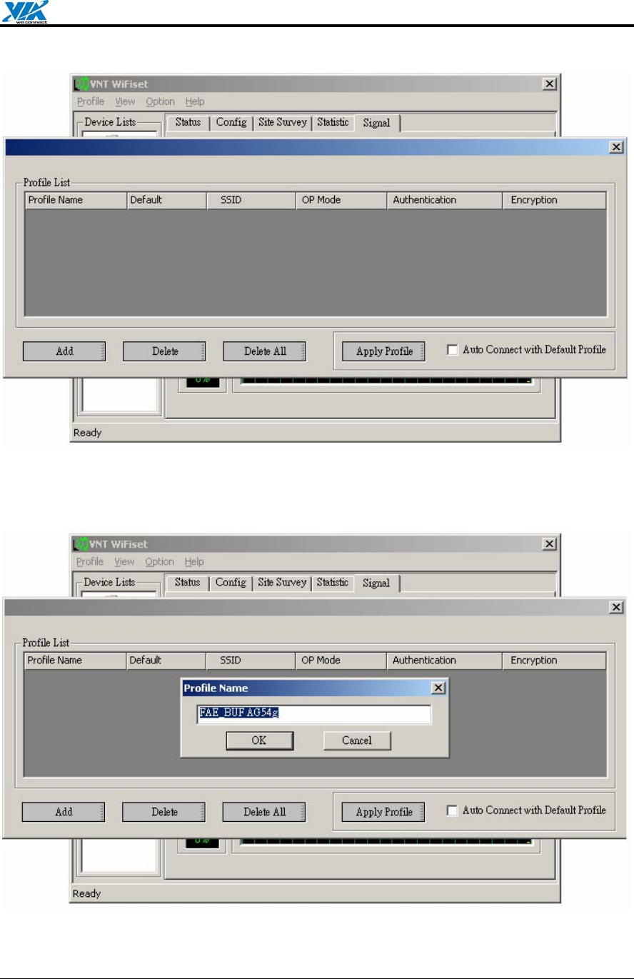
Step 1. Click Profile in WiFiset’s menu bar, and then click Add to create a new profile based
on the current network’s configurations.
VIA Technologies, Inc. User's Manual
Revision 1.0 • June 6, 2006 - 13 - Windows Utilities
Figure 8. WiFiset—Adding a new profile
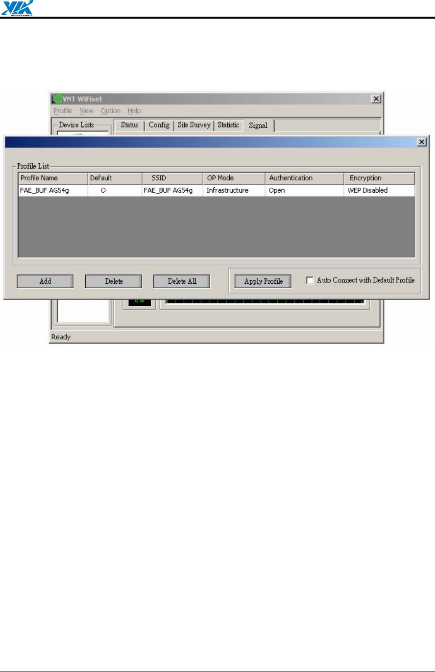
Step 2. Enter a name for the new profile, and then click OK.
Figure 9. WiFiset—Profile Name
VIA Technologies, Inc. User's Manual
Revision 1.0 • June 6, 2006 - 14 - Windows Utilities
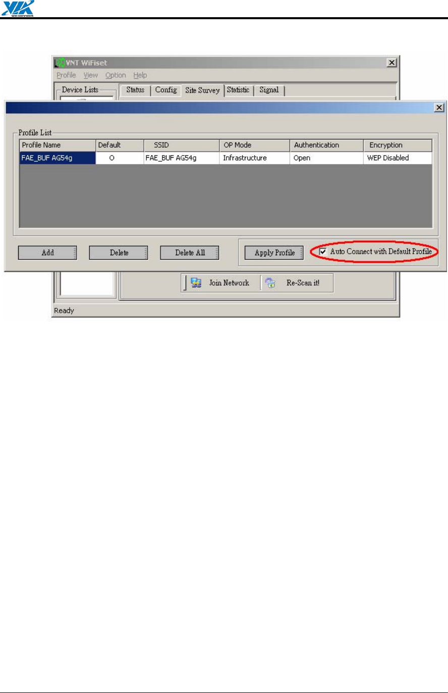
Step 3. The new profile is now successfully added to the Profile List, and it’s set to be a
default one automatically.
Figure 10. WiFiset—New profile added
4.1.6.2. Default profile and automatic connection
You can configure your device to automatically connect to a network according to the default
profile.
Step 1. Select a profile name from the Profile Select box.
Step 2. Click the Default Profile button.
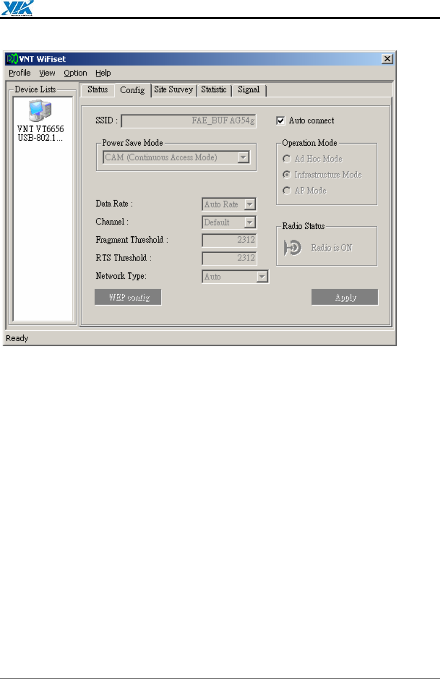
Step 3. Select the check box for Auto Connect with Default Profile, and then click the
Apply Profile button.
VIA Technologies, Inc. User's Manual
Revision 1.0 • June 6, 2006 - 15 - Windows Utilities
Figure 11. WiFiset—Auto Connect with Default Profile
Note: Once the device is set to automatically connect with a netowork according to the
default profile, most of the options under WiFiset’s Config tab would become unavailable,
and therefore appear dimmed—except for Power Save Mode and Auto connect. In addition,
a check mark would now appear in the Auto connect check box.
VIA Technologies, Inc. User's Manual
Revision 1.0 • June 6, 2006 - 16 - Windows Utilities
Figure 12. WiFiset—Auto connect
4.2. WPA Networking
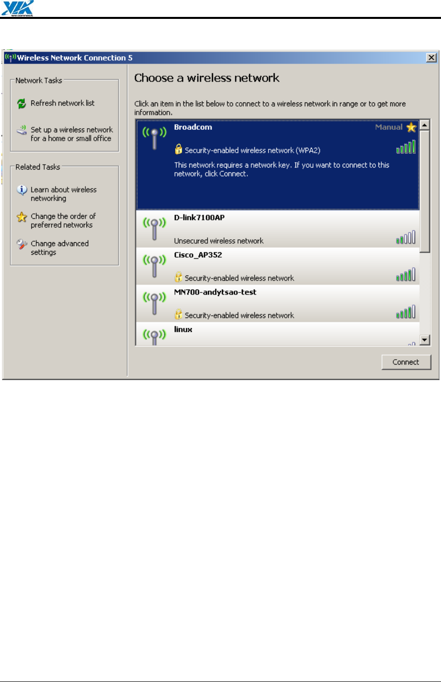
VT6655 supports Windows XP Wireless Zero Configuration service for connecting to a Wi-Fi
Protected Access (WPA) network.
Step 1. Open Wireless Network Connection.
VIA Technologies, Inc. User's Manual
Revision 1.0 • June 6, 2006 - 17 - Windows Utilities
Figure 13. Wireless Network Connection
Step 2. Click a wireless network from the list of available networks, and then click Connect.
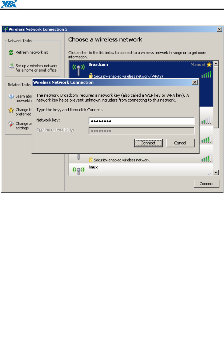
Step 3. Enter the network key, also known as WEP key or WPA key.
VIA Technologies, Inc. User's Manual
Revision 1.0 • June 6, 2006 - 18 - Windows Utilities
Figure 14. Wireless Network Connection—Network key

VIA Technologies, Inc. User's Manual
Revision 1.0 • June 6, 2006 - 19 - Appendix A: Terminology
Appendix A: Terminology
ad hoc network A network composed solely of stations within mutual communication
range of each other via the wireless medium (WM).
access point (AP) Any entity that has station functionality and provides access to the
distribution ser-vices, via the wireless medium (WM) for associated stations.
Station (STA) Any device that contains an IEEE 802.11 conformant medium access
control (MAC) and physical layer (PHY) interface to the wireless medium (WM).
RTS (Request To Send) The frame type used to deign the RTS-CTS clearing
exchange. RTS frames are used when the frame that will be transmitted is larger than
the RTS threshold.
CTS (Clear To Send) The frame type used to acknowledge receipt of a Request to
Send and the second component used in the RTS-CTS clearing exchange used to
prevent interference from hidden nodes.
WEP (Wired Equivalent Privacy) The optional cryptographic confidentiality algorithm
specified by IEEE 802.11 used to provide data confidentiality that is subjectively
equivalent to the confidentiality of a wired local area network (LAN) medium that does
not employ cryptographic techniques to enhance privacy.
authentication The service used to establish the identity of one station as a member
of the set of stations authorized to associate with another station.
WPA (Wi-Fi Protected Access) A specification of standards-based, interoperable
security enhancements that strongly increase the level of data protection and access
control for existing and future wireless LAN systems.

VIA Technologies, Inc. User's Manual
Revision 1.0 • June 6, 2006 - 20 - Appendix B: Important Notices
Appendix B: Important Notices
Federal Communications Commission Interference Statement
This equipment has been tested and found to comply with the limits for a Class B digital
device, pursuant to Part 15 of the FCC Rules. These limits are designed to provide
reasonable protection against harmful interference in a residential installation. This
equipment generates uses and can radiate radio frequency energy and, if not installed and
used in accordance with the instructions, may cause harmful interference to radio
communications. However, there is no guarantee that interference to radio or television
reception, which can be determined by turning the equipment off and on, the user is
encouraged to try to correct the interference by one of the following measures.
- Reorient or relocate the receiving antenna.
- Increase the separation between the equipment and receiver.
- Connect the equipment into an outlet on a circuit different from that
to which the receiver is connected.
- Consult the dealer or an experienced radio/TV technician for help.
This device complies with Part 15 of the FCC Rules. Operation is subject to the following two
conditions: (1) This device may not cause harmful interference, and (2) this device must
accept any interference received, including interference that may cause undesired operation.
FCC Caution: Any changes or modifications not expressly approved by the party responsible
for compliance could void the user's authority to operate this equipment.
IMPORTANT NOTE:
FCC Radiation Exposure Statement:
This equipment complies with FCC radiation exposure limits set forth for an uncontrolled
environment. This equipment should be installed and operated with minimum distance 20cm
between the radiator & your body.
This transmitter must not be co-located or operating in conjunction with any other antenna or
transmitter.
VIA Technologies, Inc. declared that VNT6656G6A10/VNT6656G6A40 is limited in CH1~11
from 2412 to 2462 MHz by specified firmware controlled in USA.

VIA Technologies, Inc. User's Manual
Revision 1.0 • June 6, 2006 - 21 - Appendix B: Important Notices
This device is intended only for OEM integrators under the following conditions:
The antenna must be installed such that 20 cm is maintained between the antenna and users,
and
The transmitter module may not be co-located with any other transmitter or antenna.
As long as 2 conditions above are met, further transmitter test will not be required. However,
the OEM integrator is still responsible for testing their end-product for any additional
compliance requirements required with this module installed (for example, digital device
emissions, PC peripheral requirements, etc.).
IMPORTANT NOTE: In the event that these conditions can not be met (for example certain
laptop configurations or co-location with another transmitter), then the FCC authorization is
no longer considered valid and the FCC ID can not be used on the final product. In these
circumstances, the OEM integrator will be responsible for re-evaluating the end product
(including the transmitter) and obtaining a separate FCC authorization.

VIA Technologies, Inc. User's Manual
Revision 1.0 • June 6, 2006 - 22 - Appendix B: Important Notices
Manual Information That Must be Included
The OEM integrator has to be aware not to provide information to the end user regarding
how to install or remove this RF module in the users manual of the end product which
integrate this module.
The users manual for OEM integrators must include the following information in a
prominent location “ IMPORTANT NOTE: To comply with FCC RF exposure
compliance requirements, the antenna used for this transmitter must be installed to
provide a separation distance of at least 20 cm from all persons and must not be co-
located or operating in conjunction with any other antenna or transmitter.