VISTEON ELECTRONICS FRANCE MI Measurement Interface User Manual WML C30 r2 0
VISTEON ELECTRONICS FRANCE Measurement Interface User Manual WML C30 r2 0
Contents
- 1. Users Manual 1
- 2. Users Manual 2
Users Manual 1

Page 1 of 10
WML-C30_User_Manual
25th Oct 2004
COMMERCIAL IN CONFIDENCE
This material may not in whole or part be copied, stored electronically or communicated to third parties
without MITSUMI ELECTRIC CO., LTD’s prior agreement in writing.
WML- 30## User Manual (system model: MI)
The purpose of this manual is to explain correct way how to integrate module WML- 30## to the end
product. It includes procedures that shall assist you to avoid unforeseen problems.
This manual presents information that shows how module and OEM product, where module integrated,
complies with regulations in certain regions. Any modifications, not expressly approved by the
manufacturer could void the authority to operate in these regions.
Content
1.General
2. Module design application.
3. Regulatory and Safety Compliance. European Union.
3.1 Declaration about performed tests.
3.2. Labelling
4. FCC Regulatory Information
4.1 Labelling.
4.2 Antenna implementation notes.
5. Other regulatory notes for OEM.
6. A separate approval.
1. General
This Bluetooth radio module has to be installed and used in accordance with the technical
description/installation instructions provided by the manufacturer.
This Bluetooth radio module is intended to be placed on the market in all States, where
the Bluetooth™ technology and the used frequency band is released.
For detail information concerning type approval of this module (e.g. where this module is
already pre-approved) please contact the authorised local distributor or the manufacturer.
The system may only be implemented in the configuration that was authorized.
Note that any changes or modifications to this equipment not expressly approved by
the manufacturer could void the user’s authority to operate this equipment.

Page 2 of 10
WML-C30_User_Manual
25th Oct 2004
COMMERCIAL IN CONFIDENCE
This material may not in whole or part be copied, stored electronically or communicated to third parties
without MITSUMI ELECTRIC CO., LTD’s prior agreement in writing.
2. Module design application.
2.1 Model Number
Model number Contents
1st # N : without Antenna , A : with Antenna
WML-C30## 2nd # B : BCSP , H : UART , U : USB
2.2 Hardware: Version 1
This document describes the reference design for application as follows.
2.3 FEATURES
1 ) Wireless communication module conforming to Bluetooth Ver.1.2.
2 ) Small and thin size achieved through use of high density mounting technology.
WML-C30N# : 13.2 x 18.8 x 2.05mm
WML-C30A# : 13.2 x 24.8 x 2.05mm
3 ) High sensitivity: -80dBm
4 ) UART and PCMIF interfaces enable wide range of applications.
5 ) Conforms to FCC, CE and other countries’ EMI standards.
6 ) Supports Bluetooth Class1.
7 ) Built-in Link controller and Link Manager Protocol.
8 ) HCI interface over UART and USB.
2.4 APPLICATIONS
Notebook PCs, mobile phones, digital cameras, PC peripherals, PDA, Car
WML-C30## has Bluetooth chip, Flash ROM and Crystal inside.
UART/USB HCI interface and PCM interface are used for customer’s application.
Following figure shows Software Stack for WML-C30## and customer’s
application as example.
Bluetooth Chip
RF+BB (BC2 External)
Flash ROM
WML-C30##
UART
PCM
Crystal
Balun
BPF
USB
Regulator (1.8V)
Chip Antenna
PIO
VDD (3.3V)
PA
RF SW
Page 3 of 10
WML-C30_User_Manual
25th Oct 2004
COMMERCIAL IN CONFIDENCE
This material may not in whole or part be copied, stored electronically or communicated to third parties
without MITSUMI ELECTRIC CO., LTD’s prior agreement in writing.
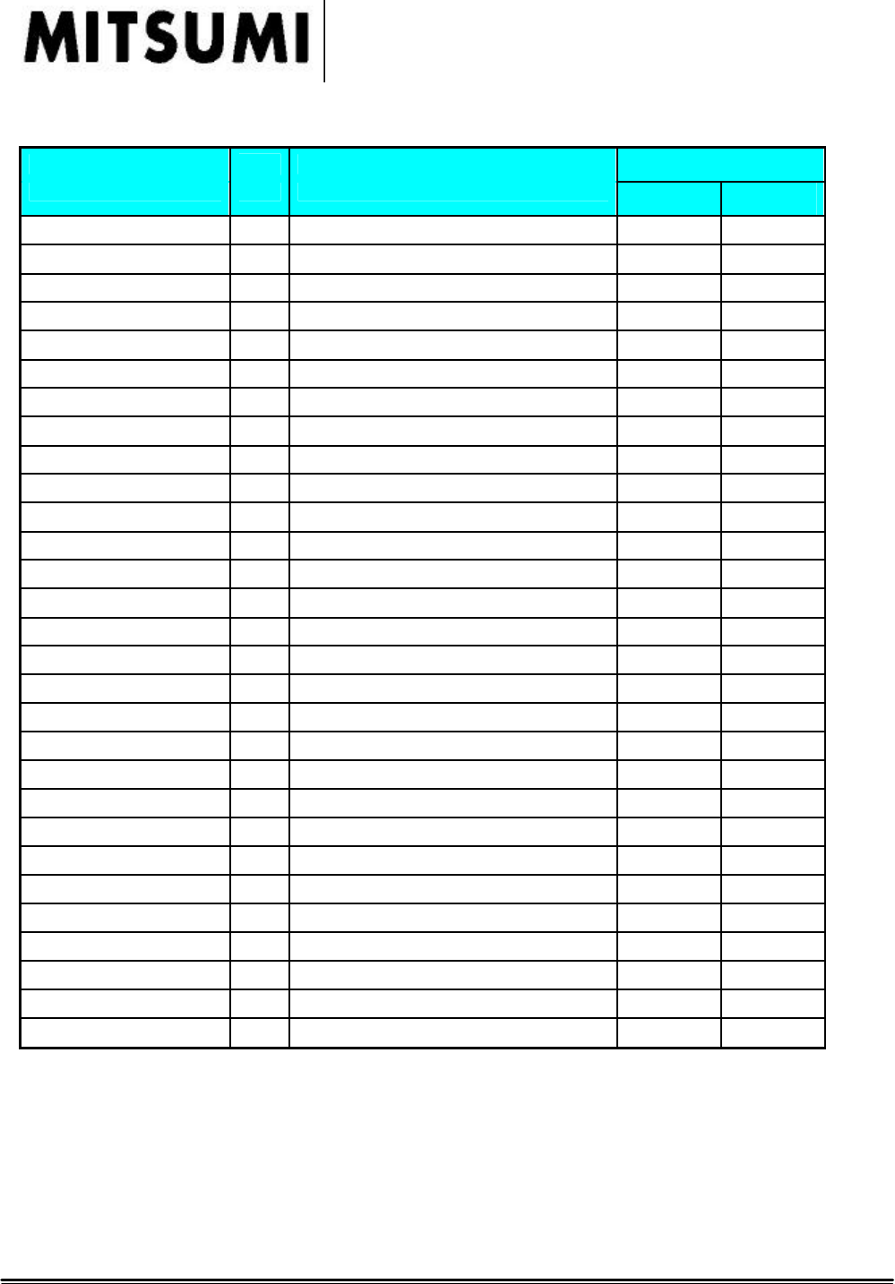
2.5 Terminal functions
Symbol I/O
Description Terminal Numbers
USB UART/
BCSP
ANT I/O RF input/output 26 26
GND Ground 1 1
GND Ground 12 12
GND Ground 25 25
GND Ground 27 27
GND Ground 28 28
GND Ground 29 29
PCM_CLK I/O Synchronous PCM data clock 7 7
PCM_IN I Synchronous PCM data input 9 9
PCM_SYNC I/O Synchronous data strobe 8 8
PCM_OUT O Synchronous PCM data out 10 10
PIO [2] / USB_PULL_UP I/O Programmable I/O line / USB pull-up 19 19
PIO [3] / USB_RESUME I/O Programmable I/O line / USB resume 20 20
PIO [4] I/O Programmable I/O line 22 22
PIO [5] I/O Programmable I/O line 21 21
PIO [6] I/O Programmable I/O line 3 3
PIO [7] I/O Programmable I/O line 4 4
RESET I Reset if high 5 5
SPI_MISO O Synchronous Serial Interface data output 24(N.C.*) 24(N.C.*)
SPI_CSB I Chip select for Synchronous Serial Interface 23(N.C.*) 23(N.C.*)
SPI_CLK I Synchronous Serial Interface Clock 6(N.C.*) 6(N.C.*)
SPI_MOSI I Synchronous Serial Interface data input 2(N.C.*) 2(N.C.*)
UART_CTS I Asynchronous serial data CTS 16(N.C.*) 16
UART_RTS O Asynchronous serial data RTS 15(N.C.*) 15
UART_TX O Asynchronous serial data output 14(N.C.*) 14
UART_RX I Asynchronous serial data input 13(N.C.*) 13
USB_D+ I/O USB Data + 17 17(N.C.*)
USB_D- I/O USB Data - 18 18(N.C.*)
VDD Supply voltage 3.3V 11 11
* N.C. = Open
Page 4 of 10
WML-C30_User_Manual
25th Oct 2004
COMMERCIAL IN CONFIDENCE
This material may not in whole or part be copied, stored electronically or communicated to third parties
without MITSUMI ELECTRIC CO., LTD’s prior agreement in writing.
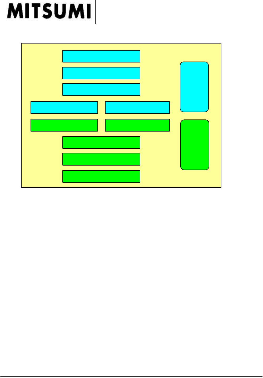
2.6 Software Stack for module and customer side example
API
L2CAP
RFCOMM/SDP
USB port driver UART port driver
HCI USB port driver HCI UART port driver
LMP
Link manager
Baseband / RF
Customer
Stack
Module
Stack

Page 5 of 10
WML-C30_User_Manual
25th Oct 2004
COMMERCIAL IN CONFIDENCE
This material may not in whole or part be copied, stored electronically or communicated to third parties
without MITSUMI ELECTRIC CO., LTD’s prior agreement in writing.
3. Regulatory and Safety Compliance . European Union.
3.1 Declaration about performed tests.
The Mitsumi module WML-C30## is wireless data transmission system. This ‘Bluetooth’
module can be integrated into various end products.
MITSUMI declares that The Mitsumi module WML-C30## complys with the following directive
and standards:
Directive 1999/5/EG (R&TTE Directive):
EN 300328-2 V1.2.1 (11-2001), Radio Equipment and Systems (RES); Wideband
transmission systems; Technical characteristics and test conditions for data transmission
equipment operating in the 2,4 GHz ISM band and using spread spectrum modulation
techniques. Part 2: Harmonized EN covering essential requirements under article 3(2) of the
R&TTE directive.
EN 301489-01 V1.3.1 (09/2001), Electromagnetic Compatibility and radio spectrum
Matters (ERM); ElectroMagnetic Compatibility (EMC) standard for radio equipment and
services; Part 1: Common technical requirements
EN 301489-17 V1.1.1 (09-2000), Electromagnetic Compatibility and radio spectrum
Matters (ERM); ElectroMagnetic Compatibility (EMC) standard for radio equipment and
services; Part 17: Specific conditions for wideband data Hiperlan equipment
We hereby declare that the human exposure of the Mitsumi module WML-C30## is below the
SAR limits specified in the EU recommendation 1999/519/EC (the applicable limits are
specified in table 1 with 2W/kg).
SAR testing must be performed to the end user devise, where WML-30## module integrated.
More detail information present on chapter 4.
The technical documentation as required by the Conformity Assessment procedure is kept at the
following address :
2-11-2,TSURUMAKI,TAMA-SHI,TOKYO,206-8567 JAPAN.
MITSUMI ELECTRIC CO.,LTD.
ACCESS DEVICE ENGINEERING DEPT.
INTERFACE EQUIPMENT BUSINESS DIVISION
COMPONENT DEVICES BUSINESS HQ
TEL:+81-42-310-5829
FAX:+81-42-310-5582
Page 6 of 10
WML-C30_User_Manual
25th Oct 2004
COMMERCIAL IN CONFIDENCE
This material may not in whole or part be copied, stored electronically or communicated to third parties
without MITSUMI ELECTRIC CO., LTD’s prior agreement in writing.
3.2 Labelling
CE conformity marking for product.
OEM product / application, where this radio module is integrated/ installed in , has to be labelled in
accordance to R&TTE directive, Article 12. An auxiliary label is included in the packaging to the
radio module, which can be used for that purpose and has to be permanently affixed to the OEM
product/ application.
Regulatory information on the OEM devise should contain following labelling :
Approved in accordance to R&TTE directive transmitter module marked by “ CE product
label”, manufactured by MITSUMI incorporated to OEM product.
More detail information present below in chapter 5.
Page 7 of 10
WML-C30_User_Manual
25th Oct 2004
COMMERCIAL IN CONFIDENCE
This material may not in whole or part be copied, stored electronically or communicated to third parties
without MITSUMI ELECTRIC CO., LTD’s prior agreement in writing.
4. FCC Regulatory Information
The Federal Communication Commission Radio Frequency Interference Statement
includes the following paragraph:
This equipment has been tested and found to comply with the limits pursuant to Part 15 of the FCC
Rules.
These limits are designed to provide reasonable protection against harmful interference in a residential
installation.
This equipment generates, uses and radiates radio frequency energy and, if not installed and used in
accordance with the instructions, may cause harmful interference to radio communication.
However, there is no guarantee that interference will not occur in a particular installation. If this
equipment does cause harmful interference to radio or television reception, which can be determined
by turning the equipment off and on, the user is encouraged to try to correct the interference by one or
more of the following measures:
-Reorient or relocate the receiving antenna.
-Increase the separation between the equipment and receiver.
-Connect the equipment into an outlet on a circuit different from that to which the
receiver is connected.
-Consult the dealer or an experienced radio / TV technician for help.
Not Authorized modification could void authority to use this equipment.
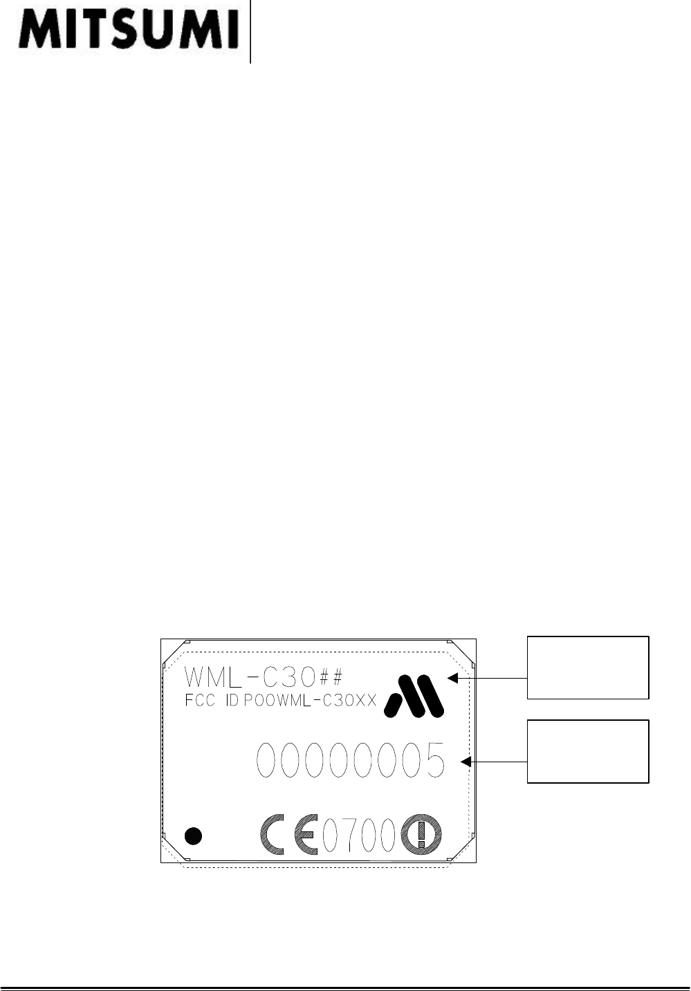
4.1 Labelling.
MITSUMI module WML 30## labelled as below.
]
Module without antenna
MITSUMI
Company Logo
Module’s Serial
Number

Page 8 of 10
WML-C30_User_Manual
25th Oct 2004
COMMERCIAL IN CONFIDENCE
This material may not in whole or part be copied, stored electronically or communicated to third parties
without MITSUMI ELECTRIC CO., LTD’s prior agreement in writing.
Module with antenna
FCC Regulatory information. OEM devise should contain labelling that:
Approved in accordance to FCC rules transmitter module marked by FCC-ID POOWML-C30XX label,
manufactured by MITSUMI incorporated to OEM product. When its not possible, in user manual
should be included such information.
For example :
“This device complies with Part 15 of the FCC Rules. Operation is subject to the
following two conditions: (1) this device may not cause harmful interference, and (2)
this device must accept any interference received, including interference that may cause
undesired operation.” This device contains
FCC-ID POOWML-C30XX
The modules can be integrated in the following ways:
a) if the minimum distance 2,5 cm between the antenna and the body of theuser or nearby persons is
ensured, so a statement in the users manual forend product is not necessary, and product where this
module incorporated can be used as portable application.
b) In case that the distance 2,5 cm between the antenna and the body ofthe user or nearby
persons cannot be ensured, the users manual of the endproduct in which the module will be integrated
has to inform the user about a minimum distance of 20 cm between the equipment and the body if the
equipment is considered for mobile application
c) In case that the distance 2,5 cm between the antenna and the body of the user or nearby
persons cannot be ensured, and equipment, where this module incorporated intend to use as portable
devise, evaluation against the applicable SAR limits is required.
RF-exposure statement. Label example:
RF-exposure statement.
This mobile modular transmitter must have a separation distance of at least 20 cm between
the antenna and the body of the user or nearby persons. With a separation distance of 20cm
or more, the MPE limits are well above the potential this module is capable to produce.
MITSUMI
Company Logo
Module’s Serial
Number
Page 9 of 10
WML-C30_User_Manual
25th Oct 2004
COMMERCIAL IN CONFIDENCE
This material may not in whole or part be copied, stored electronically or communicated to third parties
without MITSUMI ELECTRIC CO., LTD’s prior agreement in writing.
All this labelling will be placed on the final product, clearly visible to all persons exposed to the
transmitter. The specific location on the final product will be consistent with each same final
product, but will vary in location across various final products, and in any case will always be
clearly visible to all persons exposed to the transmitter. The physical size of the label and font size
of the lettering will be dependent on the size of the final product, but in any case will always be
clearly visible to all persons exposed to the transmitter
4.2 Antenna implementation notes.
Any antenna of a similar type witch listed in antenna declaration may be used without retesting.
Use of an antenna of a different type than the tested antenna or one that exceeds the gain of a
tested antenna would require retesting and new approval by either a Telecommunication
Certification Body or the Commission. Manufacturers OEM would be expected to supply a list of
acceptable antenna types with applications for equipment authorization.
External antenna that should be less than +2.14dBi maximum antenna gain can be used.
Model Name Manufacturer Max.Gain [dBi]
HAN8030B2R4GT TDK 2.14
DA095S-2450M NEC TOKIN 2.14
KIA1003 KYOCERA 2.14
AHD1403-244ST01 Mitsubishi Materials 2.14
AHD1206-244ST01 Mitsubishi Materials 2.14
YCE-5223 Yokowo -1
Radio module WML-30## can be incorporated into many different devices. The modules generally
consist of a completely self-contained radiofrequency transmitter missing only an input and a
power source to make it functional. Once the modules are authorized by the Commission under our
certification procedure, they may be incorporated into a number of host devices such as, PCs or
PDAs, which have been separately authorized. The completed product generally is not subject to
requirements for further certification by the FCC.
More detail information present below in chapter 5.
5. Other regulatory notes for OEM.
Modular transmitters save manufacturers the time and any related expenses that would be incurred if
a new equipment authorization were needed for the same transmitter when it is installed in a new
device. This means that it can be integrated into end products without further testing or approval
listing. The manufacturer must state the MITSUMI part number and product reference in his literature
in order to meet the requirements of the Bluetooth and regulatory. This should be clearly indicated in
the OEM manuals.
The purchaser / integrator ( developer) must satisfy all relevant FCC, SAR, EMC and Radio regulations
which apply to their finished product. We believe such parties have the technical competence to ensure
that the systems they deploy continue to comply with all those rules.
Further information and guidance on this subject and other equipment authorization matters can be
found under

Page 10 of 10
WML-C30_User_Manual
25th Oct 2004
COMMERCIAL IN CONFIDENCE
This material may not in whole or part be copied, stored electronically or communicated to third parties
without MITSUMI ELECTRIC CO., LTD’s prior agreement in writing.
-Regarding FCC regulatory information on the FCC’s website at:
www.fcc.gov/oet/info/database/letters/.
- Regarding R&TTE directive
http://europa.eu.int/comm/enterprise/rtte/dir99-5.htm
6. A separate approval.
A separate approval of the device into which the module is incorporated is only required when it cannot
be insured that the conditions on the module grant will be met. The purchaser must satisfy all relevant
FCC, EMC and Radio regulations R&TTE directive which apply to their finished product.