VISTEON ELECTRONICS FRANCE MI Measurement Interface User Manual MI GB v4
VISTEON ELECTRONICS FRANCE Measurement Interface MI GB v4
Contents
- 1. Users Manual 1
- 2. Users Manual 2
Users Manual 2
1
MI NOTICE
Johnson Controls Inc.
18, Chaussée Jules César
BP 340 – OSNY
95526 CERGY PONTOISE CEDEX - FRANCE
!xxxx0!
21837618-7 X0 GB.doc 02/03/06
2

3
GENERAL SAFETY PRECAUTIONS
• Ensure you read the following instructions carefully.
• Follow all the warnings and instructions shown on the products. The International
Electrical Symbols used on the device and in this notice are explained in table 1 at the
end of this document.
• Disconnect the equipment from the wall socket before cleaning. Do not use cleaning
fluids or aerosols. Use a slightly damp cloth for cleaning.
• This equipment must only be used with the battery and mains adapter supplied by
us.
• These instructions contain information and warnings which must be followed by the
user to ensure the equipment is used and maintained safely.
• Equipment category II: 400V overvoltage class II (IEC61010-1 electrical safety).
• Pollution level 2: non conducting pollution with occasional temporary conductivity
caused by condensation (IEC61010-1 electrical safety).
IMPORTANT
To avoid the risk of electrocution:
• Live components are accessible when the equipment is open. The unit must be
disconnected from the power source before any operation or repair inside the
unit.
• Do not use the equipment if the unit or the connections are damaged.
• The battery access cover must be locked during use.
• Do not use the equipment in the rain.
• Any operation other than replacement of the battery must be carried out by an
after sales service technician who is qualified to do so and knows the risks
involved.
4
• Federal Communication Commission Interference Statement
This equipment has been tested and found to comply with the limits for a Class B
digital device, pursuant to Part 15 of the FCC Rules. These limits are designed
to provide reasonable protection against harmful interference in a residential
installation. This equipment generates, uses and can radiate radio frequency
energy and, if not installed and used in accordance with the instructions, may
cause harmful interference to radio communications. However, there is no
guarantee that interference will not occur in a particular installation. If this
equipment does cause harmful interference to radio or television reception, which
can be determined by turning the equipment off and on, the user is encouraged to
try to correct the interference by one of the following measures:
- Reorient or relocate the receiving antenna.
- Increase the separation between the equipment and receiver.
- Connect the equipment into an outlet on a circuit different from that
to which the receiver is connected.
- Consult the dealer or an experienced radio/TV technician for help.
This device complies with Part 15 of the FCC Rules. Operation is subject to the
following two conditions: (1) This device may not cause harmful interference,
and (2) this device must accept any interference received, including interference
that may cause undesired operation.
FCC Caution: Any changes or modifications not expressly approved by the party
responsible for compliance could void the user's authority to operate this
equipment.
5
• IMPORTANT NOTE:
FCC Radiation Exposure Statement:
This equipment complies with FCC radiation exposure limits set forth for an
uncontrolled environment. This equipment should be installed and operated with
minimum distance 20cm between the radiator & your body.
This transmitter must not be co-located or operating in conjunction with any
other antenna or transmitter.
Information to User:
The users manual or instruction manual for an intentional or unintentional
radiator shall caution the user that changes or modifications not expressly
approved by the party responsible for compliance could void the user’s authority
to operate the equipment.
Canada-Industry Canada(IC)
Operation is subject to the following two conditions: 1) this device may not
cause interference and 2) this device must accept any interference, including
interference that may cause undesired operation of the device.
6
Content
1- Description ........................................................................................................ 8
1-1 Probe..........................................................................................................................8
1-2 Probe supply ..............................................................................................................8
2- Use ..................................................................................................................... 9
2-1 Connection diagram.................................................................................................10
3- technical specifications ................................................................................. 11
3-1 Equipment environment...........................................................................................11
4- Maintenance .................................................................................................... 12
4-1 battery:.....................................................................................................................12
4-1-1 Removing and refitting the battery...................................................................12
4-1-2 Recharging the battery......................................................................................13
4-2 Scrapping the battery ...............................................................................................13
5- Cleaning........................................................................................................... 13
6- Accessories..................................................................................................... 13
8- International electrical symbols.................................................................... 14
7- After sales service .......................................................................................... 14
7
8
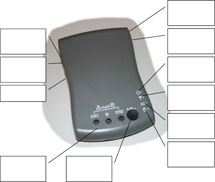
1- Description
1-1 Probe
1-2 Probe supply
The probe may be supplied by:
- The battery of the vehicle via the MI synchronization cable
- The self contained battery
- The mains adapter only to charge the self contained battery
Power LED
Communicatio
n LED
Self battery
contained LED
Operation in
progress LED
USB connector
to PC
USB HUB
output
Not used
Power switch
Mains adapter
connector
MI
synchronization
cable connector
Connectors for
measurements
Not used

9
2- Use
Warning
When working with voltages greater than 33 V RMS, 46 V peak or 70V continuous, take
care as these voltages pose a risk of electrocution.
Use MI in accordance with the following instructions:
• ensure it is powered only by the internal battery,
• connect it to the central diagnostic unit using Bluetooth mode only,
• disconnect all other USB leads, MI synchronization lead…
• cover over all connector openings using the rubber covers provided for this
purpose.
Important
To avoid damage to the MI, follow the instructions below:
Use the terminals and function corresponding to the measurements to be made.
In ohmmeter mode, disconnect the circuit supply before checking its resistance or
continuity.
Observe the temperature range for operation; do not expose the unit to heat behind a
window or leave it in the cold.
10
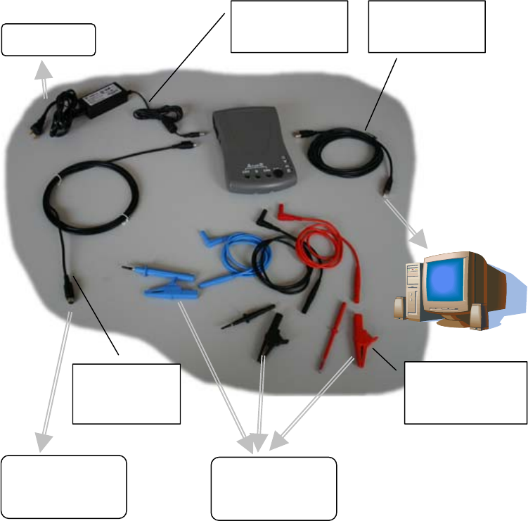
2-1 Connection diagram
Mains adapter
cable
USB cable
To vehicle for
taking
measuremen
t
To vehicle for
Power Supply
MI
synchronization
cable
Test pins and
crocodile clips
To mains

11
3- technical specifications
3-1 Equipment environment
Mains adapter:
Input: 100-240V AC 1A 50-60Hz
Output: 12V DC 1.67A
The removable plug for the mains power distribution board is used as a breaker device
for the mains power source.
This mains adapter is used only to charge the MI self contained battery.
MI Probe:
Input: 8-16V DC Imax 2.5A
Battery:
Type Li Ion 3.2V 2200mAH
Battery life: 1hour 30 minutes at 25°C
. CONDITIONS FOR USE
Temperature for operation with internal battery in place:
in internal battery recharge mode: from 0°C to +45°C
in "measuring" mode: from -20°C to +60°C
in store: from -20°C to +45°C
Temperature for operation with internal battery removed from the unit:
in "measuring" mode: from -30°C to +70°C
in store: from -30°C to +80°C
Relative humidity: 0% to 90%
Operating altitude: 2,000 m
Outside of these limits, the unit is not within normal conditions of use and may not
operate correctly.
12
4- Maintenance
Any operation other than replacement of the battery must be carried out by an after
sales service technician who is qualified to do so and knows the risks involved
Only use the accessories and consumables supplied by us: measuring cables,
connectors, spare battery.
4-1 Battery:
Warning
Do not reverse, incinerate or mutilate battery. This can cause toxic material or gas
leakage and/or explosion.
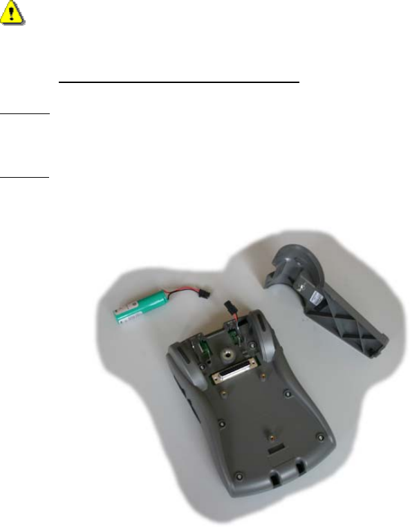
4-1-1 Removing and refitting the battery
Removal
Disconnect all accessories from the MI, turn it off if it is operating, open the cover on the
back of the probe and remove the battery.
Refitting
Fit the battery into position, connecting it without forcing it.
The battery fitting polarity MUST be observed (connector is fool proofed).
Refit the cover.

13
4-1-2 Recharging the battery
The battery must ONLY be recharged using the charger integrated into the MI.
Just connect the probe to the mains using the mains power adapter or to the car using the
MI synchronization cable (refer to the connection diagram).
Make sure you observe the recharge temperatures shown in the technical specifications.
4-2 Scrapping the battery
The battery must not be thrown away. It must be returned to the manufacturer for
recycling.
5- Cleaning
Disconnect the power before any cleaning operation. Use a damp cloth. Do not use
solvents.
6- Accessories
Battery Type Li Ion 3.2V 2200mAH 218368073
MI synchronization cable 218365548
Adaptater AC/DC 218365598
Mains adapter cable xxxxx
USB lead 218365556
Measurement leads red, black & blue 218374109
Tests pin red, black & blue 218374120
Crocodile clamps red, black & blue 218374117
14
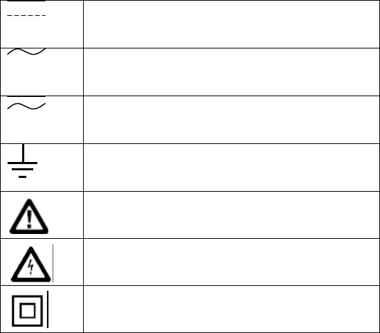
8- International electrical symbols
DC (Direct current)
AC (Alternating current)
AC or DC
Earth ground
Warning, refer to the notice for information
Warning against electrical choc
Double insulated
7- After sales service
In the event of any problems, please contact your Johnson Controls Inc. representative.
Johnson Controls Inc.
Service après-vente
1, Avenue Pierre-Gilles de Gennes
Z.I. des Ajeux
72400 La Ferté-Bernard
France
Tel.: +33 2 43 60 43 60
Fax: +33 2 43 60 43 61