VISTEON ELECTRONICS FRANCE VI Vehicle Interface User Manual VI GB v5
VISTEON ELECTRONICS FRANCE Vehicle Interface VI GB v5
Contents
- 1. Users Manual 1
- 2. Users Manual 2
Users Manual 2
1
VI NOTICE
Johnson Controls Inc.
18, Chaussée Jules César
BP 340 – OSNY
95526 CERGY PONTOISE CEDEX - FRANCE
!xxxx0!
21837618-7 X0 GB.doc 02/03/06
2

3
GENERAL SAFETY PRECAUTIONS
• Ensure you read the following instructions carefully.
• Follow all the warnings and instructions shown on the products. The International
Electrical Symbols used on the device and in this notice are explained in table 1 at the
end of this document.
• Disconnect the equipment from the wall socket before cleaning. Do not use cleaning
fluids or aerosols. Use a slightly damp cloth for cleaning.
• These instructions contain information and warnings which must be followed by the
user to ensure the equipment is used and maintained safely.
• Pollution level 2: non conducting pollution with occasional temporary conductivity
caused by condensation (IEC61010-1 electrical safety).
IMPORTANT
To avoid the risk of electrocution:
• Live components are accessible when the equipment is open. The unit must be
disconnected from the power source before any operation or repair inside the
unit.
• Do not use the equipment if the unit or the connections are damaged.
• The battery access cover must be locked during use.
• Do not use the equipment in the rain.
• Any operation other than replacement of the battery must be carried out by an
after sales service technician who is qualified to do so and knows the risks
involved.
4
• Federal Communication Commission Interference Statement
This equipment has been tested and found to comply with the limits for a Class B
digital device, pursuant to Part 15 of the FCC Rules. These limits are designed
to provide reasonable protection against harmful interference in a residential
installation. This equipment generates, uses and can radiate radio frequency
energy and, if not installed and used in accordance with the instructions, may
cause harmful interference to radio communications. However, there is no
guarantee that interference will not occur in a particular installation. If this
equipment does cause harmful interference to radio or television reception, which
can be determined by turning the equipment off and on, the user is encouraged to
try to correct the interference by one of the following measures:
- Reorient or relocate the receiving antenna.
- Increase the separation between the equipment and receiver.
- Connect the equipment into an outlet on a circuit different from that
to which the receiver is connected.
- Consult the dealer or an experienced radio/TV technician for help.
This device complies with Part 15 of the FCC Rules. Operation is subject to the
following two conditions: (1) This device may not cause harmful interference,
and (2) this device must accept any interference received, including interference
that may cause undesired operation.
FCC Caution: Any changes or modifications not expressly approved by the party
responsible for compliance could void the user's authority to operate this
equipment.
5
• IMPORTANT NOTE:
FCC Radiation Exposure Statement:
This equipment complies with FCC radiation exposure limits set forth for an
uncontrolled environment. This equipment should be installed and operated with
minimum distance 20cm between the radiator & your body.
This transmitter must not be co-located or operating in conjunction with any
other antenna or transmitter.
Information to User:
The users manual or instruction manual for an intentional or unintentional
radiator shall caution the user that changes or modifications not expressly
approved by the party responsible for compliance could void the user’s authority
to operate the equipment.
Canada-Industry Canada(IC)
Operation is subject to the following two conditions: 1) this device may not
cause interference and 2) this device must accept any interference, including
interference that may cause undesired operation of the device.
6
Content
1- Description ........................................................................................................ 7
1-1 Probe..........................................................................................................................7
1-2 Probe supply ..............................................................................................................7
2- Use ..................................................................................................................... 8
2-1 Connection diagram...................................................................................................8
3- technical specifications ................................................................................... 9
3-1 Equipment environment.............................................................................................9
4- Maintenance .................................................................................................... 10
5- Cleaning........................................................................................................... 10
6- Accessories..................................................................................................... 10
8- International electrical symbols.................................................................... 11
7- After sales service .......................................................................................... 11
7
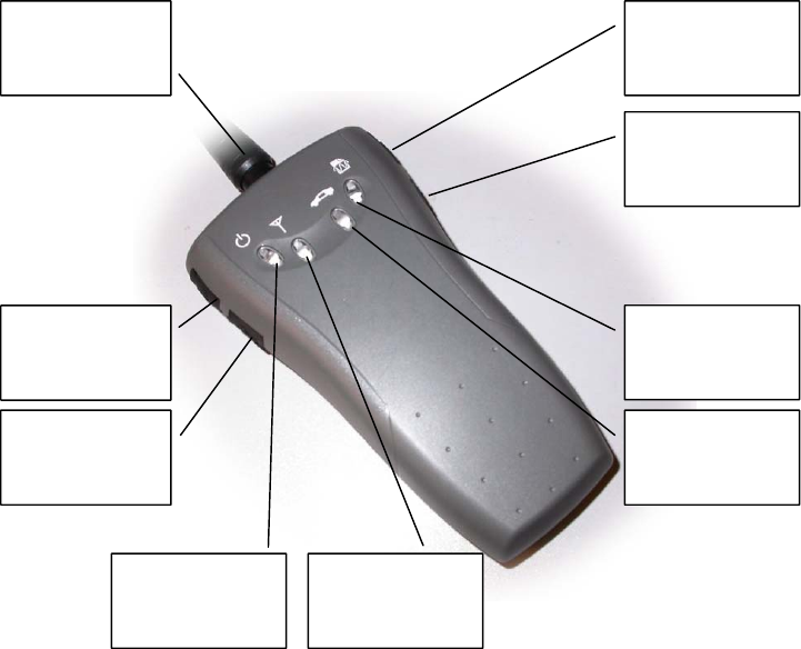
1- Description
1-1 Probe
1-2 Probe supply
The probe may be supplied by:
- The vehicle via the vehicule connexion
- The mains adapter only for software downloading and uploading
Mains adapter
connector
VDR mode
LED
Active vehicle
link LED
communication
LED
VI synchro
cable connector
USB connecto
r
Connector to
vehicle
Trigger Switch
Power supply
LED
8
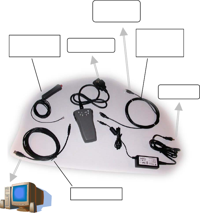
2- Use
2-1 Connection diagram
To vehicle
To mains
USB cable
Trigger
To PC
via probe
VI
synchronization
cable

9
3- technical specifications
3-1 Equipment environment
Mains adapter:
Input: 100-240V AC 1A 50-60Hz
Output: 12V DC 1.67A
The removable plug for the mains power distribution board is used as a breaker device
for the mains power source.
Mains adapter is only used for software downloading and uploading
VI Probe:
Input: 6-16V DC Pmax 10W
. CONDITIONS FOR USE
Temperature for operation :
in "measuring" mode: from -30°C to +70°C
in store: from -40°C to +80°C
Relative humidity: 0% to 90%
Operating altitude: 2,000 m
Outside of these limits, the unit is not within normal conditions of use and may not
operate correctly.
10
4- Maintenance
Any operation other than replacement of the battery must be carried out by an after
sales service technician who is qualified to do so and knows the risks involved
5- Cleaning
Disconnect the power before any cleaning operation. Use a damp cloth. Do not use
solvents.
6- Accessories
VI synchronization cable 218365548
Adaptater AC/DC 218365598
Mains adapter cable 218373941
USB lead 218365556
Trigger
11
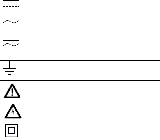
8- International electrical symbols
DC (Direct current)
AC (Alternating current)
AC or DC
Earth ground
Warning, refer to the notice for information
Warning against electrical choc
Double insulated
7- After sales service
In the event of any problems, please contact your Johnson Controls Inc. representative.
Johnson Controls Inc.
Service après-vente
1, Avenue Pierre-Gilles de Gennes
Z.I. des Ajeux
72400 La Ferté-Bernard
France
Tel.: +33 2 43 60 43 60
Fax: +33 2 43 60 43 61