VTech Telecommunications 80-0720-00 Accessory Motion Sensor User Manual
VTech Telecommunications Ltd Accessory Motion Sensor
User Manual
Motion detection
The Motion Sensor detects motion with one-minute cool off time. Once motion is detected, the
sensor will start detecting motion again only after one minute.
Pet-Immune Intrusion Detection detects the major motion of a person over several steps of
walking, while Occupancy Detection detects the relatively minor motions of sedentary occupants
such as adults, babies, and pets in a room. Pet-Immune Intrusion Detection is designed to
discern humans from small animals, so that the sensor can report movement of persons in
locked/unoccupied areas, while allowing pets to roam about such areas without being reported.
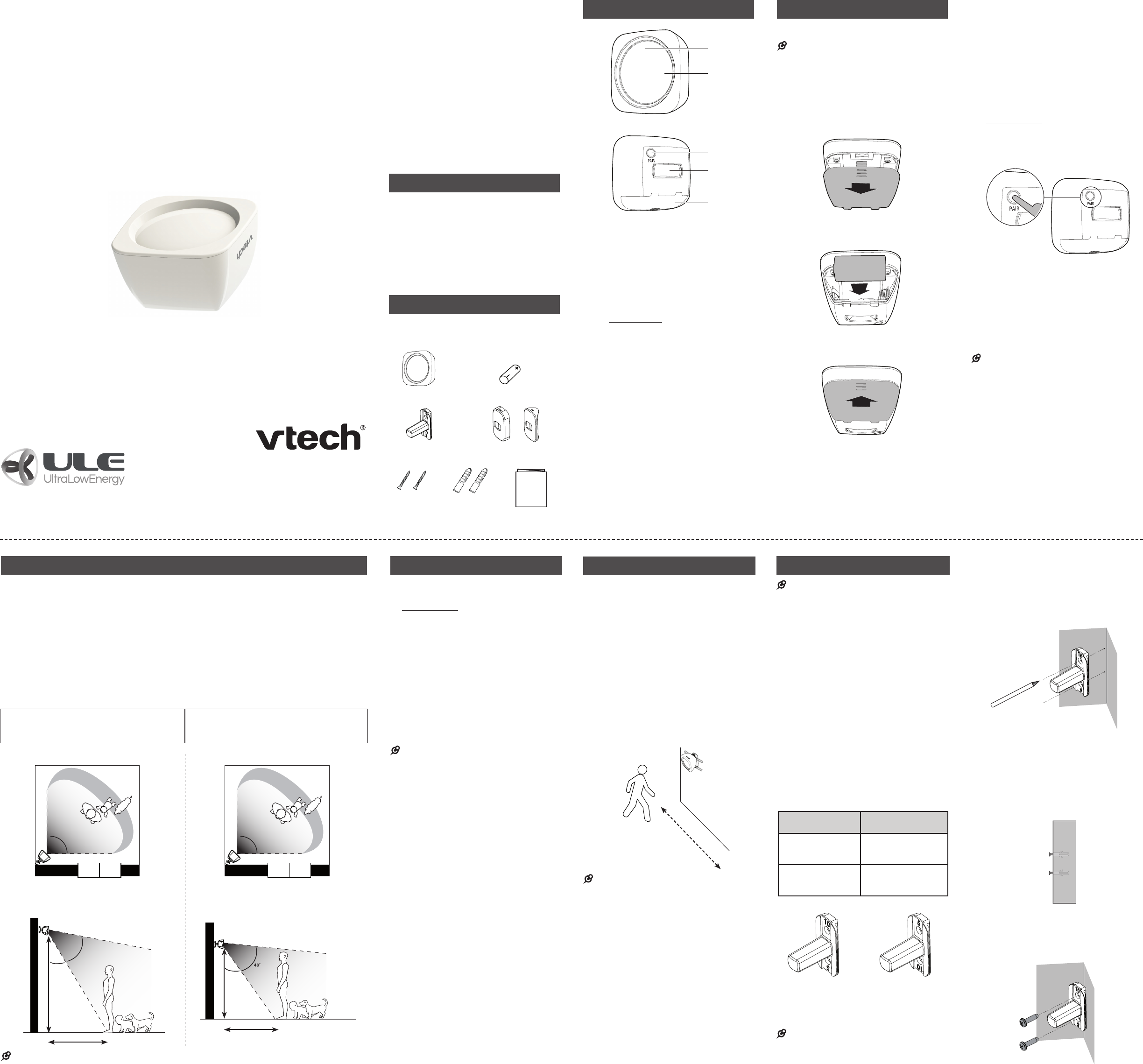
The sensor detects motion horizontally within a 90° angle, and vertically within a 48° angle. The
detection area covers up to 20 X 20 feet. For the most complete coverage of a rectangular room, it
is recommended to mount the sensor in a corner of the room.
The Motion Sensor should be placed facing away from large windows. To provide the best
detection performance, it is recommended to mount the Motion Sensor with its wall mount bracket
on the corner or the wall, within one of the two height ranges:
NOTE
The numerical values in the illustrations are for conceptual reference only. The actual angles and distances
may vary upon the change in the mounted height of the sensor.
•
Check the sensor before use
1. Place the sensor about 3.3 feet (1 meter)
from the ULE compatible product.
2. Press and hold the PAIR button on the
Motion Sensor for 3 seconds.
3. Release and immediately press the PAIR
button again to enter the test mode until
the green LED is steadily on. The test
mode will last for 5 minutes.
4. Walk across the area in front of the sensor.
The green LED on the sensor will flash.
You will receive notifications at your
ULE compatible product. Refer to the
Installation guide or user’s manual of
your ULE compatible product for the
sensor alerts.
NOTES
Make sure you have done step 3 right after
step 2. Otherwise, the sensor will enter the
pairing mode.
In the test mode, once motion is detected, the
sensor will only start to detect motion again after
5 seconds.
In the normal mode, once motion is detected,
the sensor will only start to detect motion again
after one minute. When you have received alerts
already, you will only receive alerts again for
motion detected after one minute.
•
•
•
•
•
Test the sensor signal strength
You can mount the Motion Sensor at a
location where family members or unwanted
visitors are likely to be coming and going.
1. Take the sensor to the desired mounting
location and then, temporarily mount it
at the desired height (Refer to Motion
detection section). Use adhesive tape to
hold the bracket temporarily in place.
If your ULE compatible product has a
signal checking or testing mode, enter
the respective menu option to test the
sensor signal strength.
2. Walk across the area in front of the sensor
again and check whether a good signal is
received at your ULE compatible product.
NOTES
Once motion is detected, the sensor will only
start to detect motion again after one minute.
When you have received alerts already, you will
only receive alerts again for motion detected
after one minute.
If there is no alert received when you walk
across the area in front of the sensor, move your
ULE compatible product closer to the mounting
location or move the sensor closer to the
respective product.
Depending on surroundings and obstructing
factors, like walls or cabinets, the sensor may
not transmit to the ULE compatible product
properly.
•
•
•
•
Mount the sensor
NOTES
This sensor must be mounted vertically on wall
or at a corner. Do not mount the Motion Sensor
in a horizontal orientation, or flat on the ceiling.
Make sure the mounting surface is clean. A
textured surface or any imperfections to a
smooth surface can keep the mounting tape from
making a strong bond.
This device detects or performs better when
provided with a constant and stable environment.
Avoid placing the sensor at a location which
faces direct sunlight, or exposes to areas that
may change temperature rapidly, or where there
are air ducts or substantial airflows.
If you drill the holes into an object other than a
stud, insert the screw anchors into the holes and
tap gently on the ends with a hammer until the
screw anchors are flush with the wall or ceiling.
Orientation of wall mount bracket:
The wall mount bracket’s vertical angle is not
perpendicular to the Motion Senor. According
to the mounting height selected, you need to
orient the bracket sloping upward (number “5”
up) or sloping downward (number “10” up).
Mounting height Orientation of wall
mount bracket
8.6 feet (2.6 meters) –
10.6 feet (3.2 meters)
Number “10” up
(sensor facing
downward at 10° angle)
6.6 feet (2 meters) –
8.6 feet (2.6 meters)
Number “5” up
(sensor facing
downward at 5° angle)
NOTES
For Pet-Immune Intrusion (human-only)
Detection, it is better to mount the sensor higher.
The illustrations used in the mounting steps are
with number “10” up in the wall mount bracket.
•
•
•
•
•
•
Mount on a corner of the wall
Place the wall mount bracket on a corner
of the wall and then use a pencil to mark
the top and the bottom holes as shown.
Remove the wall mount bracket and drill
two holes in the corner (7/32 inch drill bit).
If you drill the holes into a stud, go to
step 3.
-OR-
If you drill the holes into an object other
than a stud, insert the wall anchors into
the holes. Tap gently on the ends with a
hammer until the wall anchors are flush
with the corner of the wall.
Align the wall mount bracket and screws
with the holes in the corner of the wall as
shown. Tighten the screws so that the wall
mount bracket position is fixed.
1.
2.
3.
Congratulations
on purchasing your new VTech product.
Before using this product, please read
Important safety instructions.
This manual has instructions on how to
set up and register your new sensor. For
instructions on sensor settings, see the user’s
manual that came with your ULE compatible
products. Visit
www.vtechphones.com/wireless-monitoring
for a list of the latest ULE compatible products.
You may also view or download the online
User’s manual of the respective product
for a full set of installation and operation
instructions at www.vtechphones.com.
In Canada, visit www.vtechcanada.com.
Introduction
Stay on top of activity in your home, whether
it is unwanted visitors or the kids coming and
going. This sensor will let you know when it
detects activity.
This Motion Sensor has two types of
motion-detection functions: Pet-Immune
Intrusion Detection (for major motions of
adults) and Occupancy Detection (for minor
motions of adults, babies, or pets).
What’s in the box
Your product package contains the following items.
Save your sales receipt and original packaging in
the event warranty service is necessary.
Motion Sensor overview
1 – Motion detector
2 – LED light
Green for a half second when the sensor
is powered on.
Flashes green when the sensor is in the
pairing mode.
3 – PAIR button
Press and hold to enter the pairing
mode.
4 – Magnetic holder
5 – Battery compartment cover
•
•
•
Before use
Install Motion Sensor Battery
NOTES
Use only CR123A Lithium Battery.
When inserting battery, ensure polarities are
correct.
For proper operation, use battery within the
following temperature range: 0°F (-18°C) and
120°F (49°C).
Slide open battery compartment cover.
Insert the battery into the battery
compartment.
Slide the battery compartment cover back
until it securely clicks into place.
•
•
•
1.
2.
3.
Add and register a sensor
Your new VC7017 Motion Sensor can be
registered to any ULE compatible product.
Register each sensor individually to the
respective ULE compatible product before use.
Register a Motion Sensor:
Enter the registration mode by selecting
the option for adding a sensor in your
ULE compatible product. Refer to the
user’s manual of your ULE compatible
product for more detailed instructions.
Press and hold the PAIR button on the
Motion Sensor for 3 seconds, until the
LED light at the front side flashes green.
The sensor is now registering to the ULE
compatible product.
The registration process takes about
90 seconds to complete. When this
registration process completes, the LED
light on the sensor will remain steadily on for
approximately two seconds then, will turn off.
If registration fails, remove the battery from
the sensor and wait for a few seconds.
Then, re-install the battery and wait until the
LED light stops flashing. After that, begin
registration process again.
NOTES
Make sure you do not press the PAIR button
again once released after 3 seconds. Otherwise,
the sensor will enter the testing mode.
You can also download online User’s manuals at
www.vtechphones.com/support/manuals.
Replacing a sensor
If you have purchased this new VC7017
accessory sensor to replace an old sensor,
you must deregister the registered sensor
first, and then register this new sensor to your
ULE compatible product.
Deregister a sensor or all sensors:
Refer to the User’s manual of your ULE
compatible products to deregister a sensor
or all sensors.
1.
2.
•
•
•
VC7017
Accessory Motion Sensor
for use with
ULE certified systems*
User’s manual
Motion Sensor
Go to www.vtechphones.com
to register your product for
enhanced warranty support and
the latest VTech product news.
Lithium battery
User’s
manual
User’s manual
Screws for
wall mount
bracket
* Visit www.vtechphones.com/wireless-monitoring for the latest ULE compatible products.
Anchors for
wall mount
bracket
e
b
a
c
d
Wall mount bracket Wall mount bracket
covers (flat/corner)
Mounting height:
8.6 feet (2.6 meters) –
10.6 feet (3.2 meters)
Mounting height:
6.6 feet (2 meters) –
8.6 feet (2.6 meters)
Side View - Flat Wall Mounting Side View - Flat Wall Mounting
8.6 feet (2.6 meters) - 10.6 feet (3.2 meters)
You need to orient the bracket sloping
10° downward (see Mount the sensor).
6.6 feet (2 meters) - 8.6 feet (2.6 meters)
You need to orient the bracket sloping
5° downward (see Mount the sensor).
Place the Motion Sensor facing away from large windows.
Top View - Corner Mounting
Shooting area
19.7 inches
60 degrees
22.8 inches
Shooting area
19.7
inches
50 degrees
18.3
inches
63 inches
90o
Intrusion
Detection
Occupancy
Detection
Place the Motion Sensor facing away from large windows.
Top View - Corner Mounting
Shooting area
19.7 inches
60 degrees
22.8 inches
Shooting area
19.7
inches
50 degrees
18.3
inches
63 inches
90o
Intrusion
Detection
Occupancy
Detection
Height: 7.6 feet (2.3 meters)
Detection
area
5.5 feet (1.7 meters)
36o
Detection
area
48o
Height: 10 feet (3.3 meters)
6 feet (2 meters)
31o
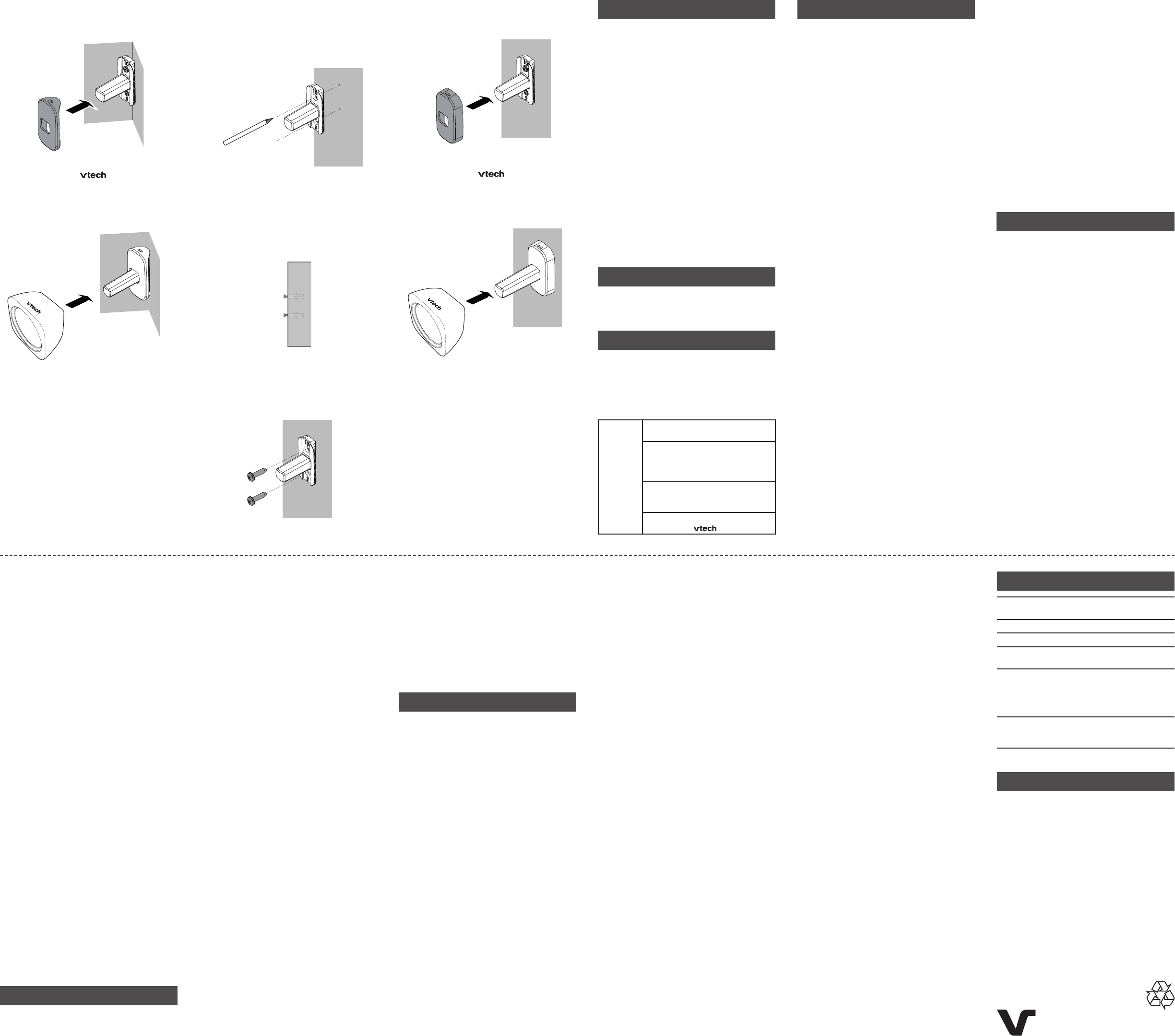
Mount on the flat wall
Place the wall mount bracket on a wall
and then use a pencil to mark the top and
the bottom holes as shown. Remove the
wall mount bracket and drill two holes in
the wall (7/32 inch drill bit).
If you drill the holes into a stud, go to
step 3.
-OR-
If you drill the holes into an object other
than a stud, insert the wall anchors into
the holes. Tap gently on the ends with a
hammer until the wall anchors are flush
with the wall.
Align the wall mount bracket and screws
with the holes in the wall as shown.
Tighten the screws so that the wall mount
bracket position is fixed.
1.
2.
3.
Push the wall mount bracket cover
towards the wall mount bracket, until it
securely clicks into place.
5. Holding with the logo facing up,
hook the Motion Sensor on the wall mount
bracket installed, until the magnetic holder
and the wall mount bracket are attached
firmly.
4. General product care
Taking care of your sensor
Your sensor contains sophisticated electronic and
optical parts, so it must be treated with care. Avoid
touching the sensor’s polyethylene front window.
Avoid rough treatment
Place the sensor down gently. Save the original
packing materials to protect your sensor if you ever
need to ship it.
Avoid water
Your sensor can be damaged if it gets wet. Do not
use the sensor outdoors in the rain, or handle it with
wet hands. Do not install the sensor near a sink,
bathtub or shower.
Electrical storms
Electrical storms can sometimes cause power
surges harmful to electronic equipment. For your
own safety, take caution when using electrical
appliances during storms.
Cleaning your sensor
Your sensor has a durable plastic casing that should
retain its luster for many years. Clean it only with a
dry non-abrasive cloth. Do not use
dampened cloth or cleaning solvents of any kind.
The front window may be wiped gently with 70%
isopropyl alcohol on a very soft cloth.
Storage
When you are not going to use the sensor for
some time, remove the battery from the sensor.
Store the sensor in a cool and dry place.
Frequently asked questions
Below are the questions most frequently asked
about the sensor. If you cannot find the answer
to your question, visit our website at
www.vtechphones.com or call 1-844-848-8324
(1-844-84-VTECH) for customer service. In Canada,
visit our website at www.vtechcanada.com or call
1-800-267-7377.
The sensor
does not
work at all.
Make sure the CR123A lithium
battery is installed.
The sensor may be deregistered
from your ULE-compatible product.
Refer to Add and register a sensor
and register the sensor back.
The sensor may be out of range.
Move the sensor closer to your ULE
compatible product.
The sensor may be upside-down.
Make sure the logo is facing up.
Important safety instructions
When using your equipment, basic safety
precautions should always be followed to reduce
the risk of fire, electric shock and injury, including
the following:
Adult setup is required.
Do not place this product on unstable shelves,
stands, tables or other surfaces.
Children should be supervised to ensure that
they do not play with the product.
The product is not intended for use by persons
(including children) with reduced physical,
sensory or mental capabilities, or
lack of experience and knowledge, unless
they have been given supervision or
instruction concerning use of the appliance by a
person responsible for their safety.
Do not use the motion sensor in the following
areas that may cause deformation, malfunction,
or operational failure:
under direct sunlight;
areas exposed to grease or steam, such as
kitchens;
near fire or heating devices;
areas subject to extreme temperature
changes, such as next to air conditioners;
areas with IR-opaque or reflective objects
that can block IR energy that are needed for
detection;
areas where the temperature is affected by
strong illuminating objects (such as halogen
lights).
SAVE THESE INSTRUCTIONS
Battery
CAUTION: Use only the battery indicated in this
manual. There may be a risk of explosion if a
wrong type of battery is used for the sensor unit.
Do not dispose of the battery in a fire. Check
with local waste management codes for special
disposal instructions.
Do not open or mutilate the battery. Released
electrolyte is corrosive and may cause burns or
injury to the eyes or skin. The electrolyte may be
toxic if swallowed.
Exercise care in handling battery in order not to
create a short circuit with conductive materials.
1.
2.
3.
4.
5.
•
•
•
•
•
•
•
•
•
•
Precautions for users of implanted cardiac
pacemakers
Cardiac pacemakers (applies only to digital
cordless devices):
Wireless Technology Research, LLC (WTR), an
independent research entity, led a multidisciplinary
evaluation of the interference between portable
wireless devices and implanted cardiac
pacemakers. Supported by the U.S. Food and Drug
Administration, WTR recommends to physicians
that:
Pacemaker patients
Should keep wireless devices at least six inches
from the pacemaker.
Should NOT place wireless devices directly over
the pacemaker, such as in a breast pocket, when
it is turned ON.
WTR’s evaluation did not identify any risk to
bystanders with pacemakers from other persons
using wireless devices.
FCC and IC regulations
FCC Part 15
This equipment has been tested and found to comply
with the requirements for a Class B digital device
under Part 15 of the Federal Communications
Commission (FCC) rules. These requirements are
intended to provide reasonable protection against
harmful interference in a residential installation. This
equipment generates, uses and can radiate radio
frequency energy and, if not installed and used in
accordance with the instructions, may cause harmful
interference to radio communications. However,
there is no guarantee that interference will not occur
in a particular installation. If this equipment does
cause harmful interference to radio or television
reception, which can be determined by turning the
equipment off and on, the user is encouraged to
try to correct the interference by one or more of the
following measures:
Reorient or relocate the receiving antenna.
Increase the separation between the equipment
and receiver.
Connect the equipment into an outlet on a
circuit different from that to which the receiver is
connected.
Consult the dealer or an experienced radio/TV
technician for help.
Changes or modifications to this equipment not
expressly approved by the party responsible for
compliance could void the user’s authority to
operate the equipment.
This device complies with Part 15 of the FCC rules.
Operation is subject to the following two conditions:
•
•
•
•
•
•
(1) this device may not cause harmful interference,
and (2) this device must accept any interference
received, including interference that may cause
undesired operation.
To ensure safety of users, the FCC has established
criteria for the amount of radio frequency energy
that can be safely absorbed by a user or bystander
according to the intended usage of the product. This
product has been tested and found to comply with
the FCC criteria. The sensor unit shall be installed
and used such that parts of all persons’ body are
maintained at a distance of approximately 8 in
(20 cm) or more.
This Class B digital apparatus complies with
Canadian requirement:
CAN ICES-3 (B)/NMB-3(B)
Industry Canada
This device complies with Industry Canada
licence-exempt RSS standard(s).
Operation is subject to the following two conditions:
(1) this device may not cause harmful interference,
and (2) this device must accept any interference
received, including interference that may cause
undesired operation.
The term ‘’IC:‘’ before the certification/registration
number only signifies that the Industry Canada
technical specifications were met.
This product meets the applicable Innovation,
Science and Economic Development Canada
technical specifications
RF radiation exposure statement
The sensor complies with FCC RF radiation
exposure limits set forth for an uncontrolled
environment. The sensor unit should be installed
and operated with a minimum distance of 8 in (20
cm) between the sensor and all persons’ body. This
transmitter must not be co-located or operating in
conjunction with any other antenna or transmitter.
This equipment complies also with Industry Canada
RSS-102 with respect to Canada’s Health Code 6
for Exposure of Humans to RF Fields.
For C-UL and cETL compliance only
Mesures de sécurité importantes
Lorsque vous utilisez votre appareil, vous devriez
toujours suivre certaines mesures de précaution
de base afin de réduire les risques d’incendie,
d’électrocution et de blessures corporelles, dont
ceux qui suivent :
L’installation par un adulte est requise.
Ne placez pas cet appareil sur un chariot,
meuble, trépied, support de montage ni table
chancelants.
1.
2.
Les enfants devraient être supervisés afin
de vous assurer qu’ils ne jouent pas avec
l’appareil.
Le produit n’est pas conçu pour être utilisé
par des personnes (incluant des enfants) aux
capacités physiques, sensorielles ou mentales
réduites ou qui manquent d’expérience et de
connaissances, à moins qu’on leur ait donné
suffisamment de supervision ou d’instructions
relativement à l’utilisation de l’appareil par une
personne responsable de leur sécurité.
Ne pas utiliser le détecteur de mouvement dans
les domaines suivants qui pourraient déformer,
défaillance ou défaillance opérationnelle :
sous la lumière directe du soleil;
les zones exposées à la graisse ou de la
vapeur, comme les cuisines;
les incendies ou les appareils de chauffage;
les zones soumises à des changements des
températures extrêmes, comme à côté de
climatiseurs;
des zones opaques ou objets qui ne reflètent
- blocs qui sont nécessaires pour détecter les
ondes ir;
les zones où la température est affectée par
le fort éclairant objets (tels que des lampes
halogènes).
CONSERVEZ CES INSTRUCTIONS
Pile
MISE EN GARDE : Il peut y avoir un risque
d’explosion si vous utilisez le mauvais type de
piles pour l’unité du capteur.
Ne jetez pas la pile au feu. Vérifiez les
instructions spécifiques de mise aux rebus
auprès des autorités locales.
N’ouvrez pas et ne mutilez pas la pile.
L’électrolyte qui s’en échapperait est corrosif et
pourrait causer des brûlures ou des blessures
aux yeux ou à la peau. L’électrolyte est toxique
si avalé.
Soyez prudents lorsque vous manipulez les piles
afin d’éviter les courts-circuits provoqués par
des matériaux conducteurs.
Stimulateurs cardiaques implantés dans
l’organisme
Les simulateurs cardiaques (ne s’applique qu’aux
dispositifs numériques sans fil) :
L’organisme ‘Wireless Technology Research, LLC
(WTR)’, une firme de recherche indépendante,
a mené une évaluation pluridisciplinaire des
interférences entre les téléphones sans fil portatifs
et les stimulateurs cardiaques implantés dans
l’organisme. Appuyée par l’Administration des
aliments et drogues (FDA) des États-Unis, la firme
WTR recommande aux médecins:
3.
4.
5.
•
•
•
•
•
•
•
•
•
•
Avis aux détenteurs de stimulateurs cardiaques
Vous devriez maintenir les dispositifs sans fil à
au moins six pouces du simulateur cardiaque.
Ils ne doivent PAS placer le téléphone sans fil
directement sur le stimulateur cardiaque, tel que
dans une poche de chemise, lorsque celui-ci est
en marche.
L’étude effectuée par l’organisme WRS n’a
pas identifié de risque pour les détenteurs de
simulateurs cardiaques causés par les gens qui
utilisent un téléphone sans fil à proximité de ceux-ci.
Limited warranty
What does this limited warranty cover?
The manufacturer of this VTech Product warrants to
the holder of a valid proof of purchase (“Consumer”
or “you”) that the Product and all accessories
provided in the sales package (“Product”) are free
from defects in material and workmanship, pursuant
to the following terms and conditions, when
installed and used normally and in accordance
with the Product operating instructions. This limited
warranty extends only to the Consumer for Products
purchased and used in the United States of America
and Canada.
What will VTech do if the Product is not free
from defects in materials and workmanship
during the limited warranty period (“Materially
Defective Product”)?
During the limited warranty period, VTech’s
authorized service representative will repair
or replace at VTech’s option, without charge,
a Materially Defective Product. If we repair
the Product, we may use new or refurbished
replacement parts. If we choose to replace
the Product, we may replace it with a new or
refurbished Product of the same or similar
design. We will retain defective parts, modules, or
equipment. Repair or replacement of the Product,
at VTech’s option, is your exclusive remedy. VTech
will return the repaired or replacement Products to
you in working condition. You should expect the
repair or replacement to take approximately 30 days.
How long is the limited warranty period?
The limited warranty period for the Product extends
for ONE (1) YEAR from the date of purchase. If
VTech repairs or replaces a Materially Defective
Product under the terms of this limited warranty,
this limited warranty also applies to the repaired or
replacement Product for a period of either (a) 90 days
from the date the repaired or replacement Product
is shipped to you or (b) the time remaining on the
original one-year warranty; whichever is longer.
•
•
What is not covered by this limited warranty?
This limited warranty does not cover:
Product that has been subjected to misuse,
accident, shipping or other physical damage,
improper installation, abnormal operation or
handling, neglect, inundation, fire, water or
other liquid intrusion; or
Product that has been damaged due to repair,
alteration or modification by anyone other than
an authorized service representative of VTech;
or
Product to the extent that the problem
experienced is caused by signal conditions,
network reliability, or cable or antenna systems; or
Product to the extent that the problem is caused
by use with non-VTech accessories; or
Product whose warranty/quality stickers,
product serial number plates or electronic
serial numbers have been removed, altered or
rendered illegible; or
Product purchased, used, serviced, or shipped
for repair from outside the United States of
America or Canada, or used for commercial or
institutional purposes (including but not limited
to Products used for rental purposes); or
Product returned without a valid proof of
purchase (see item 2 on the next column); or
Charges for installation or set up, adjustment of
customer controls, and installation or repair of
systems outside the unit.
How do you get warranty service?
To obtain warranty service in the USA, please visit
our website at www.vtechphones.com or call
1-844-848-8324 (1-844-84-VTECH). In Canada, visit
at www.vtechcanada.com or call 1-800-267-7377.
NOTE: Before calling for service, please review the
user’s manual - a check of the Product’s controls
and features may save you a service call.
Except as provided by applicable law, you assume
the risk of loss or damage during transit and
transportation and are responsible for delivery or
handling charges incurred in the transport of the
Product(s) to the service location. VTech will return
repaired or replaced Product under this limited
warranty. Transportation, delivery or handling
charges are prepaid. VTech assumes no risk for
damage or loss of the Product in transit. If the
Product failure is not covered by this limited warranty,
or proof of purchase does not meet the terms of
this limited warranty, VTech will notify you and will
request that you authorize the cost of repair prior
to any further repair activity. You must pay for the
cost of repair and return shipping costs for the repair
of Products that are not covered by this limited
warranty.
1.
2.
3.
4.
5.
6.
7.
8.
What must you return with the Product to get
warranty service?
Return the entire original package and
contents including the Product to the VTech
service location along with a description of the
malfunction or difficulty; and
Include a “valid proof of purchase” (sales receipt)
identifying the Product purchased (Product
model) and the date of purchase or receipt; and
Provide your name, complete and correct
mailing address, and telephone number.
Other limitations
This warranty is the complete and exclusive
agreement between you and VTech. It supersedes
all other written or oral communications related to
this Product. VTech provides no other warranties for
this Product. The warranty exclusively describes all
of VTech’s responsibilities regarding the Product.
There are no other express warranties. No one
is authorized to make modifications to this limited
warranty and you should not rely on any such
modification.
State/Provincial Law Rights: This warranty gives
you specific legal rights, and you may also have
other rights, which vary from state to state or
province to province.
Limitations: Implied warranties, including those of
fitness for a particular purpose and merchantability
(an unwritten warranty that the Product is fit for
ordinary use) are limited to one year from the date
of purchase. Some states/provinces do not allow
limitations on how long an implied warranty lasts,
so the above limitation may not apply to you. In no
event shall VTech be liable for any indirect, special,
incidental, consequential, or similar damages
(including, but not limited to lost profits or revenue,
inability to use the Product or other associated
equipment, the cost of substitute equipment, and
claims by third parties) resulting from the use of this
Product. Some states/provinces do not allow the
exclusion or limitation of incidental or consequential
damages, so the above limitation or exclusion may
not apply to you.
Please retain your original sales
receipt as proof of purchase.
1.
2.
3.
Technical specifications
Frequency control Crystal controlled PLL
synthesizer
Transmit frequency 1921.536-1928.448 MHz
Channels 5
Sensor operating
temperature 0°F (-18°C) to 120°F (49°C)
Nominal effective
range Maximum power allowed
by FCC and IC. Actual
operating range may vary
according to environment
conditions at the time of use.
Power requirements Battery: Lithium 3V
Battery type: CR123A
Battery size: 2/3A
Disclaimer
This product is not designed for security purposes.
When properly installed and maintained, this
product may in some cases reduce the risk of
burglary, fire, robbery or other events occurring
without providing an alarm. VTech is not responsible
for losses, injury, or damage resulting from the use
of this product.
This product is covered by U.S. Patent #9,569,953,
#9,255,786, #9,301,412, #9,304,044, and
#D762,506. Other patents may be pending.
VTech Communications, Inc.
A member of THE VTECH GROUP OF COMPANIES.
VTech is a registered trademark of VTech Holdings Limited.
Specifications are subject to change without notice.
Copyright © 2017 for VTech Communications, Inc.
All rights reserved. 04/17. VC7017_CIB_V2.0
Designed to fit your home.
And your life.
Push the wall mount bracket cover for
corner towards the wall mount bracket,
until it securely clicks into place.
Holding with the logo facing
up, hook the Motion Sensor on the
wall mount bracket installed, until the
magnetic holder and the wall mount
bracket are attached firmly.
4.
5.