VTech Telecommunications 80-4221-00 900 MHz Cordless Phone User Manual USER GUIDE
VTech Telecommunications Ltd 900 MHz Cordless Phone USER GUIDE
USER GUIDE
VTECH ENGINEERING CANADA LTD.
TITLE Product Specification
MODEL VTH1930 (Wireless Headset Phone)
Reference: PRC 00B6 Revision: 0 Page: 1 of 31
This document is proprietary to VTECH ENGINEERING CANADA LTD.
Specifications are preliminary and are subject to change without notice. 21146
VTH1930 Wireless Headset Phone
w/IR Remote Dialcard, Corded Dialing Base,
and Remote Charge Stand
VOLUME FLASH
VTH1930
Revision History:
Revision Description Page Effective Date
1 Initial Release. All Aug 14/98
All rights reserved. No part of this document may be reproduced, loaned, or transmitted in any form or by
any means without authorization in accordance with Vtech policies and administrative procedures. This
document remains the property of Vtech Engineering Canada Ltd., and must be returned upon request.
Prepared By Ralph Tischler
Title Project Manager
Approved by Gary Rogalski
Title Engineering Manager

VTECH ENGINEERING CANADA LTD.
TITLE Product Specification
MODEL VTH1930 (Wireless Headset Phone)
Reference: PRC 00B6 Revision: 0 Page: 2 of 31
This document is proprietary to VTECH ENGINEERING CANADA LTD.
Specifications are preliminary and are subject to change without notice. 21146
CONTENTS
1 OVERVIEW ....................................................................................................................................................... 4
1.1 GENERAL DESCRIPTION.............................................................................................................................. 4
1.2 REGULATORY STANDARDS ......................................................................................................................... 4
1.3 FEATURE LIST ............................................................................................................................................. 4
1.3.1 Basic Features...................................................................................................................................... 4
1.3.2 Unique Features ................................................................................................................................... 5
1.3.3 Features Not Provided......................................................................................................................... 6
1.4 COSMETIC STYLING .................................................................................................................................... 6
1.4.1 The Base Unit Cosmetics.................................................................................................................... 7
1.4.2 Headset Unit Cosmetics...................................................................................................................... 8
1.4.3 Remote Dialcard Cosmetics................................................................................................................ 9
1.4.4 Remote Charger Cosmetics.............................................................................................................. 10
2 FUNCTIONAL KEY AND LED INDICATOR DESCRIPTIONS.............................................................. 11
2.1 HEADSET LED INDICATORS & KEY DESCRIPTIONS................................................................................. 11
2.1.1 Dual Color LED ................................................................................................................................... 11
2.1.2 Volume Up/Down keys....................................................................................................................... 11
2.1.3 FLASH Key.......................................................................................................................................... 11
2.1.4 Mic Boom............................................................................................................................................. 11
2.2 REMOTE DIALCARD LED INDICATORS & KEY DESCRIPTIONS................................................................. 11
2.2.1 PHONE KEY........................................................................................................................................ 11
2.2.2 HOLD KEY ...................................................................................................................................... 11
2.2.3 OFF KEY ......................................................................................................................................... 12
2.2.4 MEM KEY........................................................................................................................................ 12
2.2.5 INTERCOM KEY ............................................................................................................................ 12
2.2.6 REDIAL KEY ....................................................................................................................................... 12
2.2.7 VOLUME KEY.............................................................................................................................. 12
2.2.8 VOLUME KEY ............................................................................................................................... 12
2.3.9 0 ->9 Numeric Keys.............................................................................................................................. 12
2.3 BASE UNIT & CORDED HANDSET LED INDICATORS & KEY DESCRIPTIONS........................................... 12
2.3.1 POWER LED......................................................................................................................................... 12
2.3.2 SPARE BATTERY CHARGE LED ..................................................................................................... 12
2.3.3 HEADSET/EXTENSION IN USE LED ................................................................................................ 12
2.3.4 MESSAGE WAITING LED ................................................................................................................... 13
2.3.5 INTERCOM LED.................................................................................................................................... 13
2.3.6 HOLD LED.............................................................................................................................................. 13
2.3.7 INTERCOM KEY................................................................................................................................. 13
2.3.8 0 ->9 Numeric Keys.............................................................................................................................. 13
2.3.9 */TONE key............................................................................................................................................ 13
2.3.10 # key..................................................................................................................................................... 13
2.3.11 MEM KEY ............................................................................................................................................ 13
2.3.12 REDIAL KEY ....................................................................................................................................... 14
2.3.13 QUICK MEM KEY............................................................................................................................... 14
2.3.14 HOLD KEY........................................................................................................................................... 14
2.3.15 MEM/PROG KEY ........................................................................................................................... 14
2.3.16 Switchook ........................................................................................................................................ 14
2.3.17 Corded Handset VOLUME LOW/MID/HIGH ................................................................................. 14
2.3.18 SPKR RINGER OFF/LOW/HIGH SWITCH ................................................................................... 14

VTECH ENGINEERING CANADA LTD.
TITLE Product Specification
MODEL VTH1930 (Wireless Headset Phone)
Reference: PRC 00B6 Revision: 0 Page: 3 of 31
This document is proprietary to VTECH ENGINEERING CANADA LTD.
Specifications are preliminary and are subject to change without notice. 21146
2.3.19 Tone/pulse switch ......................................................................................................................... 14
2.4 REMOTE CHARGER LED INDICATORS...................................................................................................... 14
2.4.1 CHARGE STATUS LED ...................................................................................................................... 14
3 OPERATING MODES.................................................................................................................................... 15
3.1 HEADSET & REMOTE DIALCARD UNIT...................................................................................................... 15
3.1.1 Headset Phone Mode (OFF-HOOK)................................................................................................ 15
3.1.2 Headset IDLE Mode, Placed On remote Charger.......................................................................... 16
3.1.3 Headset IDLE Mode, Headset NOT Placed On remote Charger and with the Mic Boom
Switch in the DOWN Position ....................................................................................................................... 17
3.1.4 Headset IDLE Mode, Headset NOT Placed On remote Charger and with the Mic Boom
Switch in the UP Position............................................................................................................................... 17
3.1.5 Headset in HOLD Mode, OFF Charger, Mic Boom DOWN.......................................................... 18
3.1.6 Headset in HOLD Mode, OFF Charger, Mic Boom UP................................................................. 19
3.1.7 Headset in INTERCOM Mode (Mic Boom must be Down & Base Corded must be Lifted) ..... 19
3.2 BASE UNIT................................................................................................................................................. 20
3.2.1 Base Phone Mode (OFF-HOOK), Headset also in PHONE mode.............................................. 20
3.2.2 BASE IDLE Mode, Corded Headset Placed in Cradle, Headset in Idle Mode........................... 21
3.2.3 BASE IDLE Mode, Corded Headset Placed in Cradle, Headset in PHONE Mode................... 22
3.2.4 BASE in HOLD Mode, Corded Headset in cradle.......................................................................... 22
3.2.5 BASE in HOLD Mode, Corded Headset Picked Up out of Cradle............................................... 23
3.2.6 Base INTERCOM Mode .................................................................................................................... 24
4 "SPECIAL" FEATURES & OPERATING MODES ................................................................................... 25
5 ELECTRICAL SPECIFICATIONS............................................................................................................... 26
5.1 OPERATING CONDITIONS.......................................................................................................................... 26
6.2 DC ELECTRICAL CHARACTERISTICS ........................................................................................................ 26
6.3 HEADSET AUDIO SPECIFICATIONS............................................................................................................ 27
6.3 BASE CORDED AUDIO SPECIFICATIONS ................................................................................................... 28
6.4 TELEPHONE LINE INTERFACE SPECIFICATIONS ....................................................................................... 29
6.5 RADIO SPECIFICATIONS ............................................................................................................................ 30
6.6 FREQUENCY ALLOCATION TABLES ........................................................................................................... 31
6.6.1 Base Unit Frequencies....................................................................................................................... 31
6.6.2 Headset Frequencies......................................................................................................................... 31

VTECH ENGINEERING CANADA LTD.
TITLE Product Specification
MODEL VTH1930 (Wireless Headset Phone)
Reference: PRC 00B6 Revision: 0 Page: 4 of 31
This document is proprietary to VTECH ENGINEERING CANADA LTD.
Specifications are preliminary and are subject to change without notice. 21146
1 Overview
The following product spec. defines the basic cosmetics, electrical specifications and operating
functions & features of the VTH1930 wireless headset phone (WHS).
1.1 General Description
The VTH1930 is a wireless headset telephone that is based upon our PDL ADPCM core
platform. The headset unit is accompanied with an Infrared dialcard, a dialing base unit with
corded handset and a separate headset charging station.
This product is intended to address the market segment that is currently using products like our
PDL w/wired headset, but desire to have a completely contained headset unit that can be worn
for extended periods of time and does not require any type of wired beltpack.
1.2 Regulatory Standards
As a requirement for sale in the United States, the product will comply with the electrical
specifications defined in the following documents:
• FCC Part 15 Radio Emmissions Requirements
• FCC Part 68 Telephone Line Interface Requirements
• UL 1459 Safety Requirements
As a requirement for sale in Canada, the product will comply with the electrical specifications
defined in the following documents:
• IC RSS-210 Radio Emmissions Requirements
• IC CS-03 Telephone Line Interface Requirements
• CSA 225 Safety Requirements
In addition to the above mandatory regulations, the recommendations provided in EIA-470-A,
TIA 571, TIA631and IEC801-2 will be used as a design guideline.
1.3 Feature List
The following feature lists provide a brief overview of the features that are and are not provided
in this unit.
1.3.1 Basic Features
• 10 channel, 900MHz operation w/32kbps ADPCM voice coding
• Automatic search for available channel (when handset on cradle)
• 16 bit digital security code
• Pulse, DTMF, and temporary DTMF dialling modes
• 20 number speed dial memory; each number can be up to 16 digits
• Redial memory (16 digits)
• 3-AAA NiMH AAA battery pack.
• Battery charge interval: 6 days in STANDBY mode, 7 hours in PHONE mode
• Line-drop circuit included
• Extension in use & no line indication provided
• Non-volatile storage of speed dial numbers

VTECH ENGINEERING CANADA LTD.
TITLE Product Specification
MODEL VTH1930 (Wireless Headset Phone)
Reference: PRC 00B6 Revision: 0 Page: 5 of 31
This document is proprietary to VTECH ENGINEERING CANADA LTD.
Specifications are preliminary and are subject to change without notice. 21146
• Non-volatile storage of security code at base unit protects against power failure
• In-the-dark answering of incoming calls
1.3.2 Unique Features
• Headset Binaural Sound using two receivers (non HAC)
• Headset will be re-chargeable via placement on remote charger.
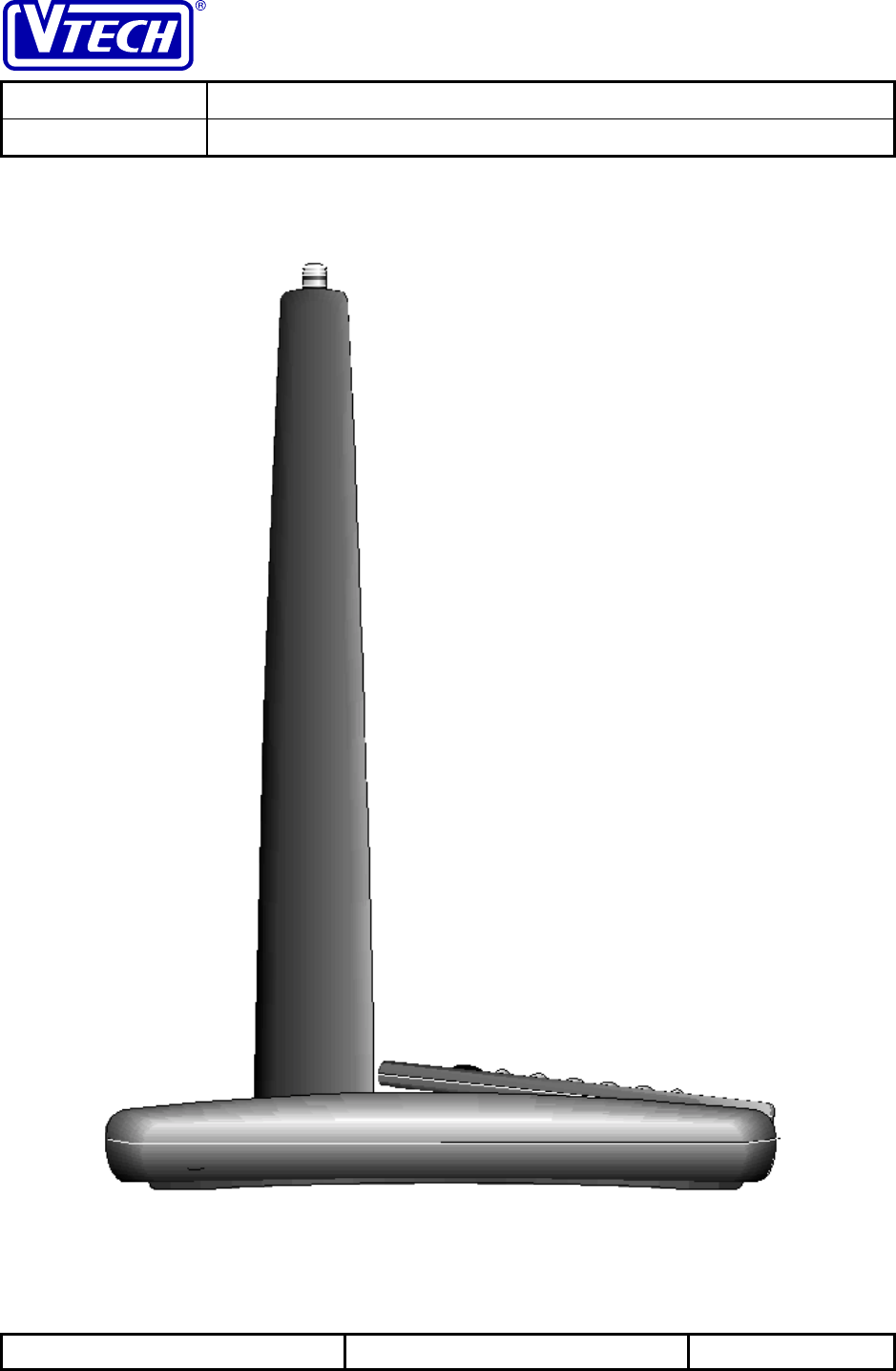
• Retractable antenna will be incorporated into headset design.
• Volume up/down keys available on headset module.
• Flash key will be available on headset module to switch between lines during a call
waiting condition.
• A CR2025 battery with an estimated lifetime of 1.5 yrs will be provided with remote
dialcard and will be easily replaced via a sliding battery door.
• The effective distance of the dialcard will be over 15 ft. in normal lighting conditions.
Under direct sunlight, the range will be limited to 4 ft (enough to allow hand held
dialing).
• A plastic loop at the top of the dialcard chassis will allow for the attachment of an
accessory strap to allow the user to hang the unit around the neck, dangle off the
wrist, or dangle of a belt clip.
• 64 different combinations of dialcard security code will be randomized in the factory
to prevent interference between different remote dialcards.
• Corded handset on base will have HI/MID/LOW volume control via slide switch on
handset.
• Base dialing keypad is provided.
• PPU will be provided for in SW as a future option.
• The base will be equipped with VMWI as an available option. The base will be
equipped with a speaker to indicate ringing, paging & other base status.
• The unit will include a ringer HI/LO/OFF on the side of the unit for volume
adjustment as well as programming of individual ringer types (base only).
• A tone pulse switch will be accessible on the bottom of the unit.
• POTS mode will be available on the base via the spare battery.
• A trickle charging bay will be provided on the base unit (20-30 hours charge time).
• Remote charger will fully charge headset battery within 2 hours.
• Remote charger LED will glow red during fast charging, and will go green after the
charge is complete. There will be no Power LED indication for the remote charger
unit.
• Headset will automatically turn OFF when placed in remote charging unit, regardless
of the mic boom position.
• Remote charger will have its own 300mAH power adapter which is interchangeable
with the base unit power adapter so the end user will not be confused.
• Headset will ring when in the remote charge and will auto-answer when lifted out of
the base cradle only if the mic boom is already in the ON position.

VTECH ENGINEERING CANADA LTD.
TITLE Product Specification
MODEL VTH1930 (Wireless Headset Phone)
Reference: PRC 00B6 Revision: 0 Page: 6 of 31
This document is proprietary to VTECH ENGINEERING CANADA LTD.
Specifications are preliminary and are subject to change without notice. 21146
1.3.3 Features Not Provided
• Will not have stutter dial detection.
• Will not have MUTE function on headset (accomplished by HOLD condition only).
• Will not have CID display in the base unit (provided in future models).
• Will not have quick charge capability in the base spare batt charger.
1.4 Cosmetic Styling
The following cosmetics renderings depict the proposed styling of the product components:
VTECH ENGINEERING CANADA LTD.
TITLE Product Specification
MODEL VTH1930 (Wireless Headset Phone)
Reference: PRC 00B6 Revision: 0 Page: 7 of 31
This document is proprietary to VTECH ENGINEERING CANADA LTD.
Specifications are preliminary and are subject to change without notice. 21146
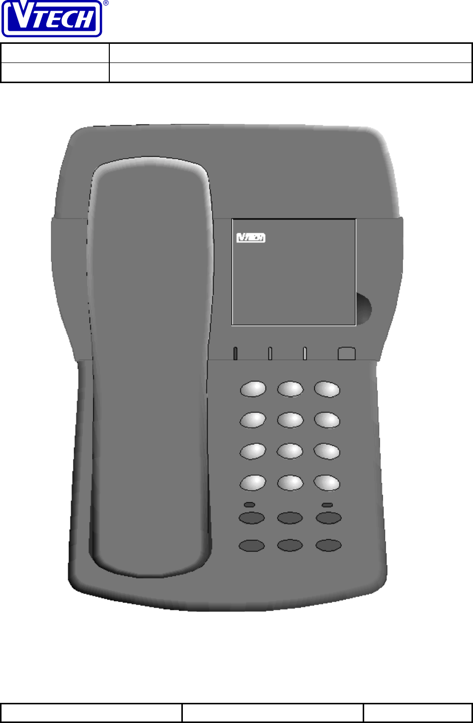
1.4.1 The Base Unit Cosmetics
MESSAGE WAITINGPOWER SPARE BAT EXT IN USE
1
11
1
2
22
2
3
33
3
4
44
4
5
55
56
66
6
7
77
78
88
8
9
99
9
*
**
*#
##
#
0
00
0
IINTERCOM PROGRAM HOLD
REDIAL MEMORY QUICK MEM
VTECH ENGINEERING CANADA LTD.
TITLE Product Specification
MODEL VTH1930 (Wireless Headset Phone)
Reference: PRC 00B6 Revision: 0 Page: 8 of 31
This document is proprietary to VTECH ENGINEERING CANADA LTD.
Specifications are preliminary and are subject to change without notice. 21146
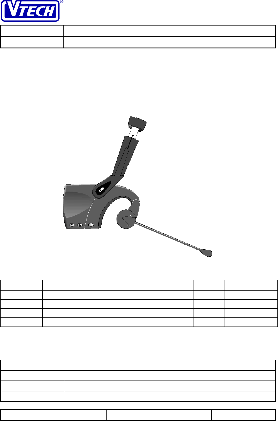
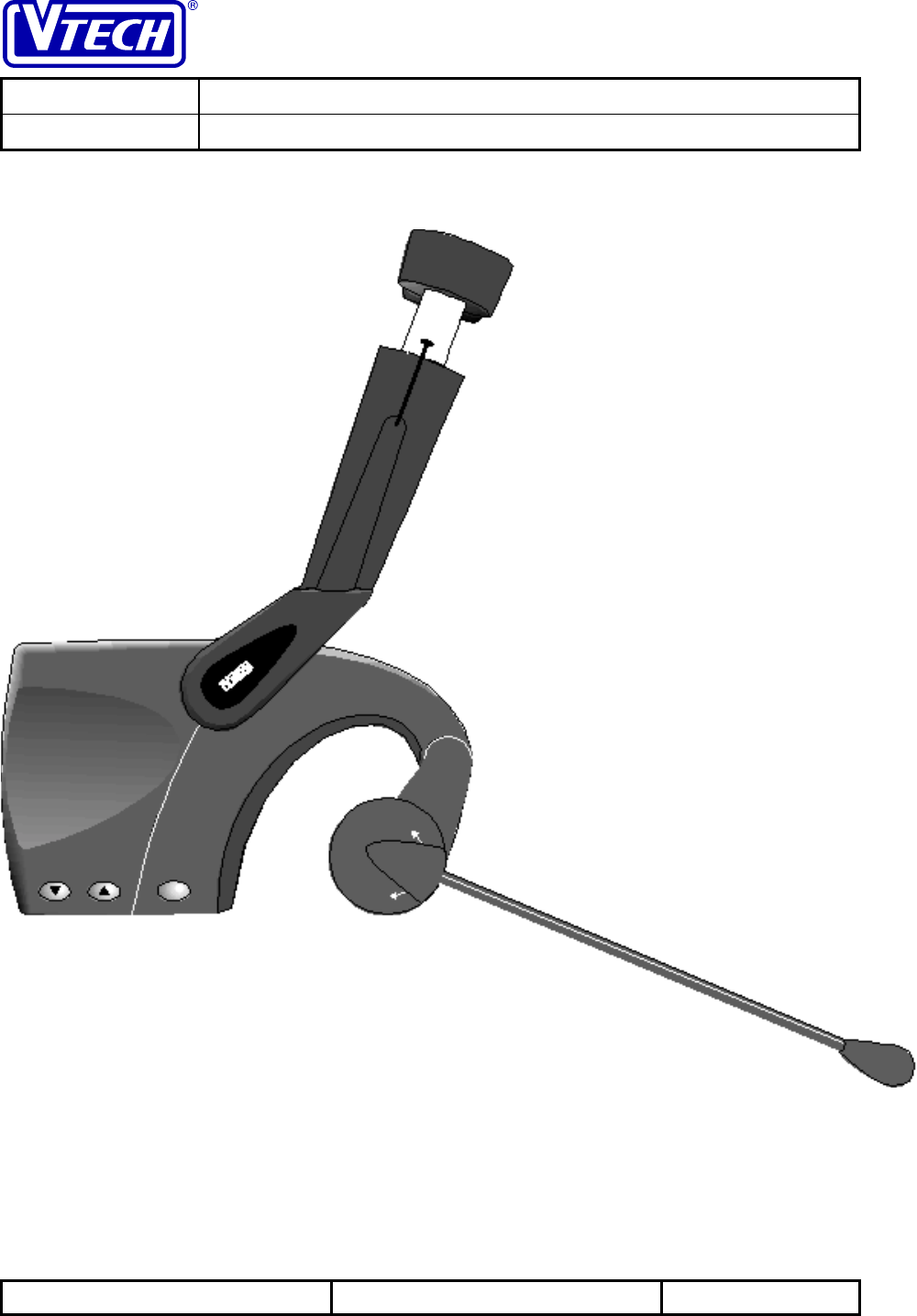
1.4.2 Headset Unit Cosmetics
VOLUME FLASH
VTH1930
VTECH ENGINEERING CANADA LTD.
TITLE Product Specification
MODEL VTH1930 (Wireless Headset Phone)
Reference: PRC 00B6 Revision: 0 Page: 9 of 31
This document is proprietary to VTECH ENGINEERING CANADA LTD.
Specifications are preliminary and are subject to change without notice. 21146
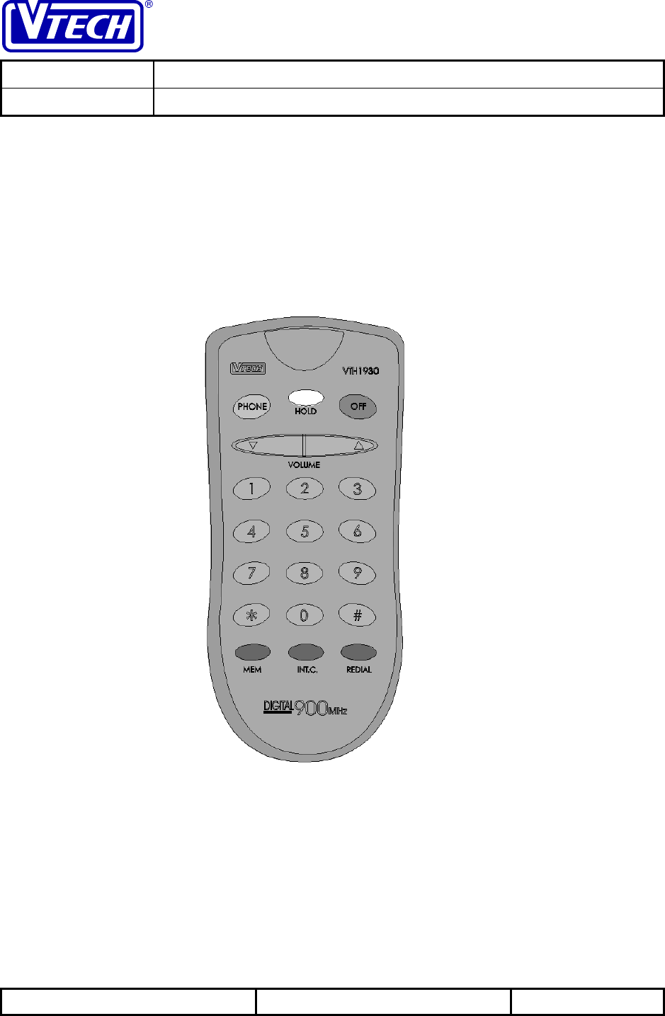
1.4.3 Remote Dialcard Cosmetics
VTECH ENGINEERING CANADA LTD.
TITLE Product Specification
MODEL VTH1930 (Wireless Headset Phone)
Reference: PRC 00B6 Revision: 0 Page: 10 of 31
This document is proprietary to VTECH ENGINEERING CANADA LTD.
Specifications are preliminary and are subject to change without notice. 21146
1.4.4 Remote Charger Cosmetics

VTECH ENGINEERING CANADA LTD.
TITLE Product Specification
MODEL VTH1930 (Wireless Headset Phone)
Reference: PRC 00B6 Revision: 0 Page: 11 of 31
This document is proprietary to VTECH ENGINEERING CANADA LTD.
Specifications are preliminary and are subject to change without notice. 21146
2 Functional Key and LED Indicator Descriptions
This section will provide a short description of the key and switch functions as well as any LED
indicators which may appear on the headset or base units.
2.1 Headset LED Indicators & Key Descriptions
2.1.1 Dual Color LED
Dual color green/red LED on headset to indicate ON (solid green), Incoming Ringing
(flashing green in cadence w/ringing), Extension or Base in use (flashing green), Low
Batt (flashing red), and Out of Range (alternating red/green).
2.1.2 Volume Up/Down keys
These keys are used to adjust the headset volume up or down; there will be 8
discrete volume steps with a step size of 3dB each. Press and hold this key changes
the handset receiver volume at a rate of one level per half second. There will be
DTMF feedback present in the headset earpiece to acknowledge the keypress.
Either key will act to temporarily mute the headset ringer during incoming ringing.
2.1.3 FLASH Key
This key will act to Flash the telephone line during an off-hook state. Otherwise,
activating this key will act to auto-answer a call during incoming ringing.
2.1.4 Mic Boom
The Mic boom is a two position switch; in the up position it acts to turn off the
headset unit and disables any input from the headset keys or the remote dialcard.
In the down position it activates the headset, acts to answer incoming ringing, and
allows the headset functions (including off) to be controlled via the remote dialcard.
2.2 Remote Dialcard LED Indicators & Key Descriptions
There are no LED indicators on the IR remote dialcard; this is done to eliminate excessive
current consumption and extend battery life.
2.2.1 PHONE KEY
Press this key to access a LINE. If the headset has already accessed a line,
pressing the PHONE key will flash the line. Pressing the PHONE key will cause the
unit to immediately access a line from any state or mode the phone is in including
hold.
2.2.2 HOLD KEY
This key has two functions. Pressing this key when the handset is off hook will
place the call on HOLD. Pressing HOLD a second time will cancel hold. Pressing
OFF will not cancel hold or end the call

VTECH ENGINEERING CANADA LTD.
TITLE Product Specification
MODEL VTH1930 (Wireless Headset Phone)
Reference: PRC 00B6 Revision: 0 Page: 12 of 31
This document is proprietary to VTECH ENGINEERING CANADA LTD.
Specifications are preliminary and are subject to change without notice. 21146
2.2.3 OFF KEY
Press this key to exit all modes. The OFF key will cause the unit to exit only the
mode that the phone is in at the time.
2.2.4 MEM KEY
Press this key during the off-hook state to access speed dial numbers.
2.2.5 INTERCOM KEY
Pressing the INT.COM key will generate a headset keybeep and send a paging
signal to the base causing it to emit a distinctive ring. When in idle mode, the base
will ring for a maximum of five times. To end the INTERCOM conversation, the user
must press the OFF key or return the mic boom to the UP position.
2.2.6 REDIAL KEY
Pressing REDIAL will immediately dial out the last number in the redial buffer. The
redial buffer size is 20 digits. During redial, the level of DTMF feedback generated
in the earpiece will be attenuated by approx.6 dB from the normal DTMF level
generated during live dialing.
2.2.7 VOLUME
KEY
Each press of this key will increment the headset receiver volume. There are a total
of 8 volume level settings. Pressing the volume up key during incoming ringing will
activate temporary ringer muting. Pressing a volume key will not generate a
keybeep.
2.2.8 VOLUME
KEY
This key operates the same as above except to decrement the headset receiver
volume.
2.3.9 0 ->9 Numeric Keys
In DTMF mode, pressing these keys will result in the appropriate DTMF tone being
sent out over the line. In PULSE mode, pressing these keys will result in the
appropriate pulse pattern being sent out over the line; A beep is heard from the
headset.
2.3 Base Unit & Corded Handset LED Indicators & Key Descriptions
2.3.1 POWER LED
This LED illuminates when the base power adapter is plugged in and power is
applied to the base unit.
2.3.2 SPARE BATTERY CHARGE LED
The Spare battery charge LED illuminates steadily when the spare battery is placed
into the base charging compartment.
2.3.3 HEADSET/EXTENSION IN USE LED
This LED flashes when the headset is off hook or when a parallel extension is picked
up.

VTECH ENGINEERING CANADA LTD.
TITLE Product Specification
MODEL VTH1930 (Wireless Headset Phone)
Reference: PRC 00B6 Revision: 0 Page: 13 of 31
This document is proprietary to VTECH ENGINEERING CANADA LTD.
Specifications are preliminary and are subject to change without notice. 21146
2.3.4 MESSAGE WAITING LED
This LED will flash whenever the base has received a VMWI signal from the C.O.. It
will remain in this state until either the cancel VMWI signal is received from the C.O.
or the base unit power is removed..
2.3.5 INTERCOM LED
This LED will illuminate whenever INTERCOM mode is active.
2.3.6 HOLD LED
This LED will illuminate whenever a call is placed on hold; it does not matter whether
the hold condition was initiated from the headset or the base.
2.3.7 INTERCOM KEY
Pressing the INT.COM key will generate a base keybeep and send a paging signal
to the headset causing it to emit a distinctive ring. When in idle mode, the headset
will ring for a maximum of five times. To end the INTERCOM conversation, the
user presses INT.COM on the base or OFF on the handset. If the handset is in
PHONE mode when the base pages it, the handset will generate a long, soft non-
intrusive ringing tone.
2.3.8 0 ->9 Numeric Keys
In DTMF mode, pressing these keys will result in the appropriate DTMF tone being
sent out over the line. If the key is held then the tone is continuously sent.
In PULSE mode, pressing these keys will result in the appropriate pulse pattern
being sent out over the line. A beep is heard from the base.
2.3.9 */TONE key
When the TONE/PULSE switch on the base is in the PULSE position, pushing this
key will change the outgoing numbers from PULSE to DTMF for the duration of the
call. In TONE mode, this sends out the DTMF tone for *.
2.3.10 # key
In DTMF mode, pressing this key sends out an appropriate DTMF tone for #. In
PULSE mode, this key is inactive.
2.3.11 MEM KEY
This key is used for recalling phone numbers stored in speed dial memory.
To dial a number stored in speed dial memory:
1.) Press SPEAKERPHONE to get a dial tone.
2.) Press MEM and the number key (00..20).
The number stored is dialed out - e.g. 555-1234.
Location 00 is shared with the QUICKMEM key and can be accessed by pressing
the QUICKMEM key or by entering speed dial location 00. MEM dialing numbers
can only be programmed from the handset.

VTECH ENGINEERING CANADA LTD.
TITLE Product Specification
MODEL VTH1930 (Wireless Headset Phone)
Reference: PRC 00B6 Revision: 0 Page: 14 of 31
This document is proprietary to VTECH ENGINEERING CANADA LTD.
Specifications are preliminary and are subject to change without notice. 21146
2.3.12 REDIAL KEY
This automatically dials the last number dialed out from the base unit. To use the
REDIAL, the user first goes off and then presses REDIAL. Pressing REDIAL will
generate a base keybeep.
2.3.13 QUICK MEM KEY
Pressing this key when in phone mode will dial out the contents of MEM location 00.
2.3.14 HOLD KEY
This puts the line on hold when in PHONE mode. Pressing HOLD will generate a
base keybeep.
2.3.15 MEM/PROG KEY
Beginning from idle mode, press and hold this to enter PROGRAM mode. An
acknowledgment keybeep will accompany this action.
2.3.16 Switchook
Lifting the corded base out of the cradle will activate phone mode on the base unit;
depressing the switchook for the correct duration will flash the line
2.3.17 Corded Handset VOLUME LOW/MID/HIGH
The base corded handset volume can be adjusted by selecting the slide switch
mounted to the side of the handset to the low, mid, or high position. There will be a
6 dB difference in the volume levels.
2.3.18 SPKR RINGER OFF/LOW/HIGH SWITCH
Sets the baseset ringer to the HIGH, LOW or OFF state.
2.3.19 Tone/pulse switch
This switch controls whether the unit will dial out using DTMF tones or using pulse
dialing. The factory default position is DTMF dialing.
2.4 Remote Charger LED Indicators
2.4.1 CHARGE STATUS LED
When the headset is not sitting on the remote charger, the Charge status LED will
be OFF. During “Quick Charging” the charge status LED will glow RED. Once the
headset battery has attained full charge, the charge status LED will Glow GREEN to
indicate that the headset is fully charged and ready to use.
VTECH ENGINEERING CANADA LTD.
TITLE Product Specification
MODEL VTH1930 (Wireless Headset Phone)
Reference: PRC 00B6 Revision: 0 Page: 15 of 31
This document is proprietary to VTECH ENGINEERING CANADA LTD.
Specifications are preliminary and are subject to change without notice. 21146
3 Operating Modes
The following section will outline in detail the operation of the product in particular modes in
accordance to various stimuli. Some sections will describe the operation of various elements in
response to different operating modes.
3.1 Headset & Remote Dialcard Unit
The headset and the Remote dialcard operation will be grouped together since the remote
dialcard is simply and Infrared extension of the headset.
3.1.1 Headset Phone Mode (OFF-HOOK)
The headset can enter PHONE mode (OFF-HOOK) in the following manner :
- Moving the mic boom switch to the extended or down position will always activate PHONE
mode.
- With the mic boom in the down position, and the unit in an ON-HOOK state, pressing the
PHONE key on the dialcard will always activate PHONE mode.
- When incoming ringing is present, pressing any key on the headset or dialcard with the
exception of the volume up/down keys will activate PHONE mode.
The response to stimuli while in PHONE mode is outlined below:
Remote Dialcard Action Response
OFF KEY ON-HOOK
PHONE KEY FLASH LINE
HOLD KEY ON-HOLD
INTERCOM NO ACTION (no Keybeep)
MEM ACCEPT MEM LOCATION
REDIAL DIAL OUT CONTENTS OF REDIAL BUFFER
VOLUME UP/DOWN INCREMENT/DECREMENT VOLUME SETTING (no keybeep)
# KEYS DIAL OUT CORRESPONDING DTMF OR PULSE DIGITS
(except * key activates temporary tone in pulse mode)
Headset Action Response
MIC BOOM TO UP POSITION ON-HOOK
FLASH KEY FLASH LINE
VOLUME UP/DOWN INCREMENT/DECREMENT VOLUME SETTING (no keybeep)
VTECH ENGINEERING CANADA LTD.
TITLE Product Specification
MODEL VTH1930 (Wireless Headset Phone)
Reference: PRC 00B6 Revision: 0 Page: 16 of 31
This document is proprietary to VTECH ENGINEERING CANADA LTD.
Specifications are preliminary and are subject to change without notice. 21146
Base Action Response
CORDED HANDSET LIFTED CORDED HANDSET OFF-HOOK
SWITCH HOOK FLASHED NO ACTION
HOLD KEY ON-HOLD
INTERCOM NON-INTRUSIVE PAGING TO HEADSET
MEM ACCEPT MEM LOCATION
REDIAL DIAL OUT CONTENTS OF REDIAL BUFFER
QUICK MEM DIAL OUT CONTENTS OF MEM LOCATION 00
PROGRAM NO ACTION
# KEYS DIAL OUT CORRESPONDING DTMF OR PULSE DIGITS
(except * key activates temporary tone in pulse mode)
Other Stimuli Response
PLACE HEADSET ON
CHARGER ON-HOOK
3.1.2 Headset IDLE Mode, Placed On remote Charger
The response to stimuli of the headset while in idle mode and resting on the remote charger is
outlined below:
Remote Dialcard Action Response
VOLUME UP/DOWN TEMPORARY HEADSET RINGER MUTING DURING
INCOMING RINGING
ALL KEYS NO ACTION
Headset Action Response
MIC BOOM TO UP/DOWN
POSITION NO ACTION
FLASH KEY NO ACTION
VOLUME UP/DOWN TEMPORARY HEADSET RINGER MUTING DURING
INCOMING RINGING
Base Action Response
INTERCOM PAGING TO HEADSET
ALL OTHER KEYS NO ACTION
Other Stimuli Response
REMOVE HEADSET FROM
CHARGER – MIC BOOM UP NO ACTION
REMOVE HEADSET FROM
CHARGER – MIC BOOM
DOWN
NO ACTION EXCEPT DURING INCOMING RI NGING WILL
AUTO ANSWER AND ENTER PHONE MODE
BASE PAGING HEADSET INTERCOM MODE CANNOT BE ENTERED ON REMOTE
CHARGER
INCOMING RINGING PHONE MODE CANNOT BE ENTERED ON REMOTE
CHARGER
VTECH ENGINEERING CANADA LTD.
TITLE Product Specification
MODEL VTH1930 (Wireless Headset Phone)
Reference: PRC 00B6 Revision: 0 Page: 17 of 31
This document is proprietary to VTECH ENGINEERING CANADA LTD.
Specifications are preliminary and are subject to change without notice. 21146
3.1.3 Headset IDLE Mode, Headset NOT Placed On remote Charger and with the Mic
Boom Switch in the DOWN Position
The response to stimuli of the headset while in idle mode, NOT resting on the remote charger
and with the mic boom down is outlined below:
Remote Dialcard Action Response
PHONE KEY OFF-HOOK
OFF KEY NO ACTION (No Keybeep)
HOLD KEY NO ACTION (No Keybeep)
INTERCOM PAGING TO BASE
MEM NO ACTION (No Keybeep)
REDIAL NO ACTION (No Keybeep)
VOLUME UP/DOWN NO ACTION (No Keybeep) EXCEPT TEMPORARY HEADSET
RINGER MUTING DURING INCOMING RINGING
# KEYS NO ACTION (No Keybeep)
Headset Action Response
MIC BOOM TO UP POSITION NO ACTION (No Keybeep)
FLASH KEY NO ACTION (No Keybeep)
VOLUME UP/DOWN NO ACTION (No Keybeep) EXCEPT TEMPORARY HEADSET
RINGER MUTING DURING INCOMING RINGING
Base Action Response
INTERCOM PAGING TO HEADSET
ALL OTHER KEYS NO ACTION
Other Stimuli Response
BASE PAGING HEADSET ONLY INTERCOM KEY WILL INITIATE INTERCOM MODE
INCOMING RINGING ALL HEADSET AND REMOTE DIALCARD KEYS WILL
ANSWER CALL, EXCEPT FOR VOLUME UP/DOWN KEYS.
3.1.4 Headset IDLE Mode, Headset NOT Placed On remote Charger and with the Mic
Boom Switch in the UP Position
The response to stimuli of the headset while in idle mode, NOT resting on the remote charger
and with the mic boom up is outlined below:
Remote Dialcard Action Response
ALL KEYS NO ACTION (No Keybeep)
VTECH ENGINEERING CANADA LTD.
TITLE Product Specification
MODEL VTH1930 (Wireless Headset Phone)
Reference: PRC 00B6 Revision: 0 Page: 18 of 31
This document is proprietary to VTECH ENGINEERING CANADA LTD.
Specifications are preliminary and are subject to change without notice. 21146
Headset Action Response
MIC BOOM TO DOWN
POSITION OFF-HOOK
FLASH KEY NO ACTION (No Keybeep)
VOLUME UP/DOWN NO ACTION (No Keybeep) EXCEPT TEMPORARY HEADSET
RINGER MUTING DURING INCOMING RINGING
Base Action Response
INTERCOM PAGING TO HEADSET
ALL OTHER KEYS NO ACTION
Other Stimuli Response
BASE PAGING HEADSET MOVING MIC BOOM TO THE DOWN POSITION WILL
INITIATE INTERCOM MODE
INCOMING RINGING ONLY MOVING MIC BOOM TO DOWN POSITION WILL
ANSWER CALL & INITIATE PHONE MODE
3.1.5 Headset in HOLD Mode, OFF Charger, Mic Boom DOWN
HOLD mode is initiated by pressing the HOLD key while the headset is in PHONE mode.
The response to stimuli of the headset while in HOLD mode is outlined below:
Remote Dialcard Action Response
PHONE KEY PHONE MODE
OFF KEY NO ACTION (No Keybeep)
HOLD KEY PHONE MODE
INTERCOM PAGES BASE
MEM NO ACTION (No Keybeep)
REDIAL NO ACTION (No Keybeep)
VOLUME UP/DOWN INCREMENT/DECREMENT VOLUME SETTING
# KEYS NO ACTION (No Keybeep)
Headset Action Response
MIC BOOM TO UP POSITION NO ACTION (No Keybeep)
FLASH KEY NO ACTION (No Keybeep)
VOLUME UP/DOWN INCREMENT/DECREMENT VOLUME SETTING
Base Action Response
INTERCOM PAGING TO HEADSET
ALL OTHER KEYS NO RELATED HEADSET ACTION
VTECH ENGINEERING CANADA LTD.
TITLE Product Specification
MODEL VTH1930 (Wireless Headset Phone)
Reference: PRC 00B6 Revision: 0 Page: 19 of 31
This document is proprietary to VTECH ENGINEERING CANADA LTD.
Specifications are preliminary and are subject to change without notice. 21146
3.1.6 Headset in HOLD Mode, OFF Charger, Mic Boom UP
The response to stimuli of the headset while in HOLD mode is outlined below:
Remote Dialcard Action Response
ANY KEY NO ACTION
Headset Action Response
MIC BOOM TO DOWN
POSITION HEADSET OFF-HOOK, CANCEL HOLD CONDITION
FLASH KEY NO ACTION (No Keybeep)
VOLUME UP/DOWN INCREMENT/DECREMENT VOLUME SETTING
Base Action Response
INTERCOM PAGING TO HEADSET
ALL OTHER KEYS NO RELATED HEADSET ACTION
3.1.7 Headset in INTERCOM Mode (Mic Boom must be Down & Base Corded must be
Lifted)
INTERCOM mode is entered by pressing the INTERCOM key on the headset to page the base;
if the base answers the page, then INTERCOM mode is enabled. INTERCOM mode can be
entered while in the IDLE or HOLD state.
The response to stimuli of the headset while in INTERCOM mode is outlined below:
Remote Dialcard Action Response
PHONE KEY PHONE MODE
OFF KEY EXIT INTERCOM & RETURN TO PREVIOUS MODE
HOLD KEY NO ACTION (No Keybeep)
INTERCOM NO ACTION (No Keybeep)
MEM NO ACTION (No Keybeep)
REDIAL NO ACTION (No Keybeep)
VOLUME UP/DOWN INCREMENT/DECREMENT VOLUME SETTING
# KEYS NO ACTION (No Keybeep)
Headset Action Response
MIC BOOM TO UP POSITION EXIT INTERCOM & ENTER IDLE MODE
FLASH KEY NO ACTION (No Keybeep)
VOLUME UP/DOWN INCREMENT/DECREMENT VOLUME SETTING
VTECH ENGINEERING CANADA LTD.
TITLE Product Specification
MODEL VTH1930 (Wireless Headset Phone)
Reference: PRC 00B6 Revision: 0 Page: 20 of 31
This document is proprietary to VTECH ENGINEERING CANADA LTD.
Specifications are preliminary and are subject to change without notice. 21146
Base Action Response
INTERCOM NO ACTION (No Keybeep)
RETURN BASE CORDED TO
CRADLE EXIT INTERCOM & RETURN TO PREVIOUS MODE
QUICK MEM EXIT INTERCOM, ENTER PHONE MODE AND DIAL OUT
QUICK MEM DIGITS
ALL OTHER KEYS NO ACTION (No Keybeep)
Other Stimuli Response
INCOMING RINGING HEADSET WILL RING & REMAIN IN INTERCOM MODE
3.2 Base Unit
3.2.1 Base Phone Mode (OFF-HOOK), Headset also in PHONE mode
The base can enter PHONE mode (OFF-HOOK) by lifting the corded handset out of its cradle,
except during Headset PAGING (which initiates INTERCOM mode).
The response to stimuli while in PHONE mode is outlined below:
Base Action Response
CORDED HANDSET
RECRADLED BASE EXITS PHONE MODE
SWITCH HOOK FLASHED LINE FLASH (except when headset is in PHONE mode)
HOLD KEY ON-HOLD
INTERCOM NO ACTION (no keybeep)
MEM ACCEPT MEM LOCATION
REDIAL DIAL OUT CONTENTS OF REDIAL BUFFER
QUICK MEM DIAL OUT CONTENTS OF MEM LOCATION 00
PROGRAM NO ACTION
# KEYS DIAL OUT CORRESPONDING DTMF OR PULSE DIGITS
(except * key activates temporary tone in pulse mode)
Remote Dialcard Action Response
OFF KEY HEADSET EXIT PHONE MODE
PHONE KEY PHONE MODE - NO LINE FLASH
HOLD KEY ON-HOLD
INTERCOM NON INTRUSIVE PAGING TONE AT BASE
MEM ACCEPT MEM LOCATION FROM B/S OR HEADSET
REDIAL DIAL OUT CONTENTS OF REDIAL BUFFER
VOLUME UP/DOWN INCREMENT/DECREMENT VOLUME SETTING (no keybeep)
# KEYS DIAL OUT CORRESPONDING DTMF OR PULSE DIGITS
(except * key activates temporary tone in pulse mode)
Headset Action Response
VTECH ENGINEERING CANADA LTD.
TITLE Product Specification
MODEL VTH1930 (Wireless Headset Phone)
Reference: PRC 00B6 Revision: 0 Page: 21 of 31
This document is proprietary to VTECH ENGINEERING CANADA LTD.
Specifications are preliminary and are subject to change without notice. 21146
MIC BOOM TO UP POSITION HEADSET EXIT PHONE MODE
FLASH KEY NO LINE FLASH
VOLUME UP/DOWN INCREMENT/DECREMENT VOLUME SETTING (no keybeep)
3.2.2 BASE IDLE Mode, Corded Headset Placed in Cradle, Headset in Idle Mode
The base is always in idle mode when the corded headset is placed in the base cradle.
The response to stimuli while in IDLE mode is outlined below:
Base Action Response
CORDED HANDSET LIFTED BASE PHONE MODE
SWITCH HOOK FLASHED N/A
HOLD KEY NO ACTION (no keybeep)
INTERCOM NO ACTION (no keybeep)
MEM NO ACTION (no keybeep)
REDIAL NO ACTION (no keybeep)
QUICK MEM NO ACTION (no keybeep)
PROGRAM PROGRAM MODE
# KEYS NO ACTION (no keybeep)
Remote Dialcard Action Response
INTERCOM BASE PAGING
ALL OTHER KEYS NO RELEVANT ACTION FOR HEADSET IDLE MODE
Headset Action Response
ALL KEYS & SWITCH NO RELEVANT ACTION FOR HEADSET IDLE MODE
Other Stimuli Response
HEADSET PAGING BASE LIFT CORDED HEADSET TO INITIATE INTERCOM MODE
INCOMING RINGING LIFT CORDED HEADSET TO INITIATE INTERCOM MODE
VTECH ENGINEERING CANADA LTD.
TITLE Product Specification
MODEL VTH1930 (Wireless Headset Phone)
Reference: PRC 00B6 Revision: 0 Page: 22 of 31
This document is proprietary to VTECH ENGINEERING CANADA LTD.
Specifications are preliminary and are subject to change without notice. 21146
3.2.3 BASE IDLE Mode, Corded Headset Placed in Cradle, Headset in PHONE Mode
The base is always in idle mode when the corded headset is placed in the base cradle.
The response to stimuli while in IDLE mode with the headset in PHONE Mode is outlined below:
Base Action Response
CORDED HANDSET LIFTED BASE PHONE MODE
SWITCH HOOK FLASHED N/A
HOLD KEY ON HOLD
INTERCOM NO ACTION (no keybeep)
MEM ACCEPT MEM LOCATION
REDIAL DIAL OUT CONTENTS OF REDIAL BUFFER
QUICK MEM DIAL OUT CONTENTS OF MEM LOCATION 00
PROGRAM NO ACTION (no keybeep)
# KEYS DIAL OUT CORRESPONDING DTMF OR PULSE DIGITS
(except * key activates temporary tone in pulse mode)
Remote Dialcard Action Response
ALL KEYS NO RELATED BASE ACTION
Headset Action Response
ALL KEYS NO RELATED BASE ACTION
3.2.4 BASE in HOLD Mode, Corded Headset in cradle
Hold mode can be initiated from either the headset or base unit by pressing the pressing the
HOLD key when either the base or headset is in PHONE mode.
The following describes the reponse to stimuli when the base is in HOLD Mode:
Base Action Response
CORDED HANDSET PICKED
UP HOLD CANCELLED - BASE PHONE MODE
SWITCH HOOK FLASHED N/A
INTERCOM NO ACTION (no keybeep)
MEM NO ACTION (no keybeep)
REDIAL NO ACTION (no keybeep)
QUICK MEM NO ACTION (no keybeep)
PROGRAM PROGRAM MODE
# KEYS NO ACTION (no keybeep)
VTECH ENGINEERING CANADA LTD.
TITLE Product Specification
MODEL VTH1930 (Wireless Headset Phone)
Reference: PRC 00B6 Revision: 0 Page: 23 of 31
This document is proprietary to VTECH ENGINEERING CANADA LTD.
Specifications are preliminary and are subject to change without notice. 21146
Remote Dialcard Action Response
PHONE KEY HOLD CANCELLED - HEADSET PHONE MODE (boom down)
HOLD KEY HOLD CANCELLED - HEADSET PHONE MODE (boom down)
INTERCOM BASE PAGING
ALL OTHER KEYS NO RELATED BASE ACTION
Headset Action Response
MIC BOOM TO DOWN
POSITION HOLD CANCELLED - HEADSET PHONE MODE
FLASH KEY NO ACTION (no keybeep)
VOLUME UP/DOWN NO ACTION
Other Stimuli Response
HEADSET PAGING BASE LIFT CORDED HEADSET TO INITIATE INTERCOM MODE
3.2.5 BASE in HOLD Mode, Corded Headset Picked Up out of Cradle
Hold mode can be initiated from either the headset or base unit by pressing the pressing the
HOLD key when either the base or headset is in PHONE mode.
The following describes the reponse to stimuli when the base is in HOLD Mode, with the corded
headset picked up out of the base cradle:
Base Action Response
CORDED HANDSET
RECRADLED NO ACTION (no keybeep)
SWITCH HOOK FLASHED HOLD CANCELLED - BASE PHONE MODE
HOLD KEY HOLD CANCELLED - BASE PHONE MODE
INTERCOM HEADSET PAGING
MEM NO ACTION (no keybeep)
REDIAL NO ACTION (no keybeep)
QUICK MEM NO ACTION (no keybeep)
PROGRAM NO ACTION
# KEYS NO ACTION (no keybeep)
Remote Dialcard Action Response
PHONE KEY HOLD CANCELLED - HEADSET PHONE MODE (boom down)
HOLD KEY HOLD CANCELLED - HEADSET PHONE MODE (boom down)
INTERCOM BASE PAGING
ALL OTHER KEYS NO RELATED BASE ACTION
Headset Action Response
MIC BOOM TO DOWN
POSITION HOLD CANCELLED - HEADSET PHONE MODE
FLASH KEY NO ACTION (no keybeep)
VOLUME UP/DOWN NO ACTION
VTECH ENGINEERING CANADA LTD.
TITLE Product Specification
MODEL VTH1930 (Wireless Headset Phone)
Reference: PRC 00B6 Revision: 0 Page: 24 of 31
This document is proprietary to VTECH ENGINEERING CANADA LTD.
Specifications are preliminary and are subject to change without notice. 21146
Other Stimuli Response
HEADSET PAGING BASE PRESS INTERCOM TO INITIATE INTERCOM MODE
3.2.6 Base INTERCOM Mode
The base can enter INTERCOM Mode by paging the headset (press INTERCOM key) and
having the headset answer the page to initiate INTERCOM. The base can also enter
INTERCOM mode in the opposite manner by answering a page from the Headset. The corded
handset is always lifted during INTERCOM mode.
The response to stimuli while in INTERCOM mode is outlined below:
Base Action Response
CORDED HANDSET
RECRADLED EXIT INTERCOM MODE
SWITCH HOOK FLASHED EXIT INTERCOM MODE - BASE PHONE MODE ACTIVE
HOLD KEY NO ACTION (no keybeep)
INTERCOM EXIT INTERCOM MODE
MEM NO ACTION (no keybeep)
REDIAL NO ACTION (no keybeep)
QUICK MEM EXIT INTERCOM, ENTER PHONE MODE AND DIAL OUT
QUICK MEM DIGITS
PROGRAM NO ACTION (no keybeep)
# KEYS NO ACTION (no keybeep)
Remote Dialcard Action Response
OFF KEY EXIT INTERCOM MODE - RETURN TO PREVIOUS MODE
PHONE KEY EXIT INTERCOM MODE - PHONE MODE
HOLD KEY NO ACTION (no keybeep)
INTERCOM EXIT INTERCOM MODE
MEM NO ACTION (no keybeep)
REDIAL NO ACTION (no keybeep)
VOLUME UP/DOWN INCREMENT/DECREMENT VOLUME SETTING (no keybeep)
# KEYS NO ACTION (no keybeep)
Headset Action Response
MIC BOOM TO UP POSITION EXIT INTERCOM MODE
FLASH KEY NO ACTION (no keybeep)
VOLUME UP/DOWN INCREMENT/DECREMENT VOLUME SETTING (no keybeep)
Other Stimuli Response
INCOMING RINGING BASE WILL RING & REMAIN IN INTERCOM MODE

VTECH ENGINEERING CANADA LTD.
TITLE Product Specification
MODEL VTH1930 (Wireless Headset Phone)
Reference: PRC 00B6 Revision: 0 Page: 25 of 31
This document is proprietary to VTECH ENGINEERING CANADA LTD.
Specifications are preliminary and are subject to change without notice. 21146
4 "Special" Features & Operating Modes
This section is also used to describe any special hardware or software features that do not fall
under the description of a particular mode.
VTECH ENGINEERING CANADA LTD.
TITLE Product Specification
MODEL VTH1930 (Wireless Headset Phone)
Reference: PRC 00B6 Revision: 0 Page: 26 of 31
This document is proprietary to VTECH ENGINEERING CANADA LTD.
Specifications are preliminary and are subject to change without notice. 21146
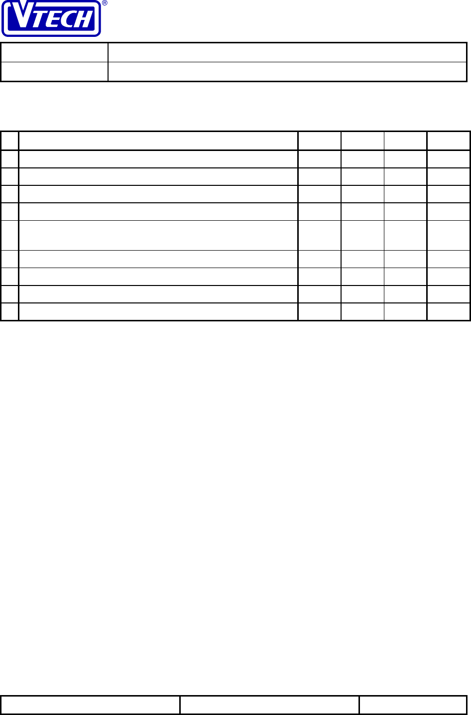
5 Electrical Specifications
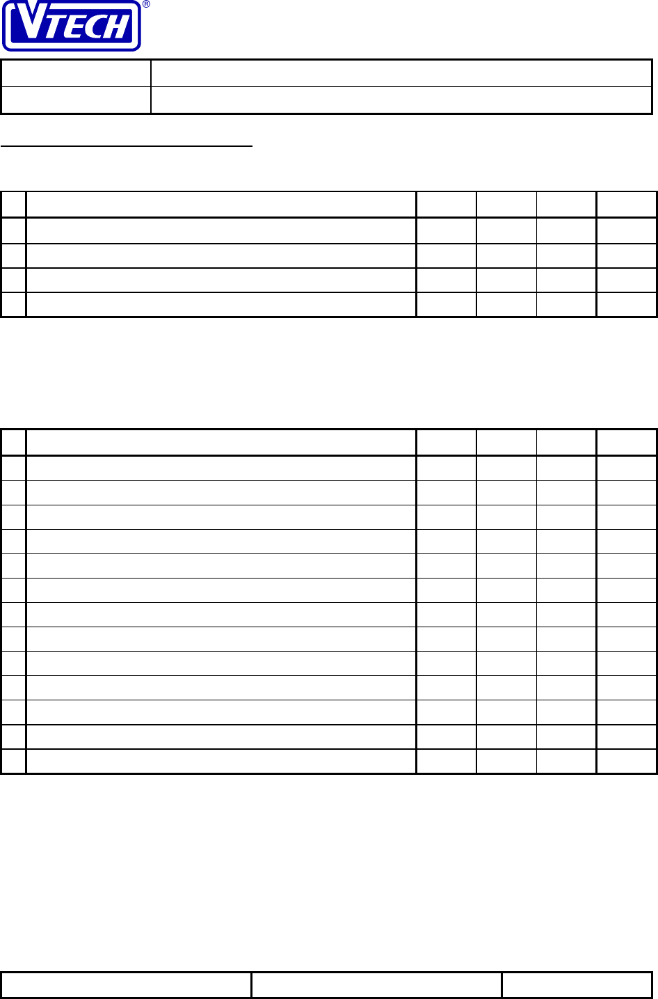
5.1 Operating Conditions
Parameter Min Typ Max Units
Operating Temperature Range 0 25150 °C
Base Unit Operating Voltage (AC Voltage, 60Hz) 96 1201144 Vrms
Base Unit Operating Voltage (AC Adapter Output) 91Vdc
Handset Operating Voltage23.2 3.614.2 Vdc
Notes: 1. Typical value represents the nominal testing value
2. Handset operates from a 3-cell NiMH Battery
6.2 DC Electrical Characteristics
Specifications marked with * are guaranteed at the nominal testing temperature and voltage on
all units with the use of automated production test equipment (ATE)
Parameter Min Typ Max Units
* Base Unit Current - Standby Mode1,2 TBD mA
* Base Unit Current - Talk Mode1,2 TBD mA
Handset Current - Sleep Mode 1 3 mA
* Handset Current - Wake Mode 45 70 mA
* Handset Current - Talk Mode 65 101 mA
* Handset Sleep Duration - Standby Mode 750 1150 ms
Handset Wake Duration - Standby Mode 52 60 ms
* Low Battery Detection Threshold (HS) 3.4 Vdc
* MCU Shutdown Threshold (HS) 3.2 Vdc
Handset Standby Time 6 Days
Handset Continuous Talk Time 7 Hours
* Loaded Cradle Charge Contact Voltage33.3 4.3 V
* Loaded Spare Battery Charge Contact Voltage31.7 2.5 V
Notes: 1. DC current from 9v power supply
2. Cradle and spare battery charge currents = 0mA
3. Voltage measured across a 50Ω charge circuit load resistor

VTECH ENGINEERING CANADA LTD.
TITLE Product Specification
MODEL VTH1930 (Wireless Headset Phone)
Reference: PRC 00B6 Revision: 0 Page: 27 of 31
This document is proprietary to VTECH ENGINEERING CANADA LTD.
Specifications are preliminary and are subject to change without notice. 21146
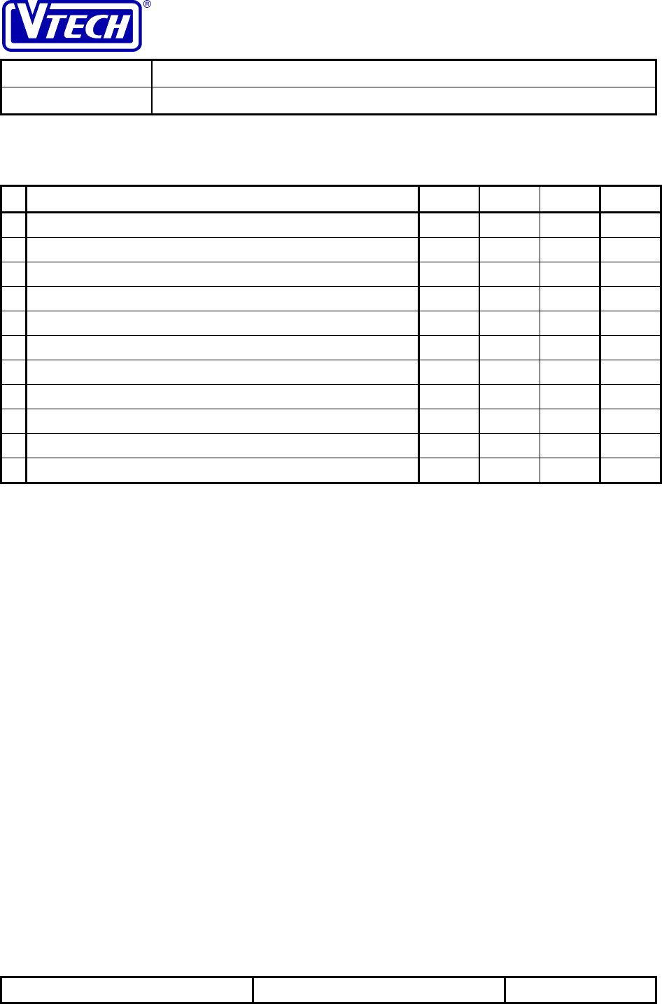
6.3 Headset Audio Specifications
Specifications marked with * are guaranteed at the nominal testing temperature and voltage on
all units with the use of automated production test equipment (ATE)
Parameter Min Typ Max Units
* Transmit Objective Loudness Rating (TOLR)1TBD dB
* Receive Objective Loudness Rating (ROLR)1,2 TBD dB
* Sidetone Objective Loudness Rating (SOLR)3TBD dB
* Receive volume adjustment range TBD dB
* Transmit Direction Acoustic Overload (into
microphone)4TBD dBspl
* Receive Direction Acoustic Overload (from receiver)4TBD dBspl
Transmit Direction Noise520 dBrnC
Receive Direction Noise2,5 35 dB(A)
Peak Acoustic Pressure6TBD dBspl
Notes: 1. Tested using 0kft of simulated telephone line
2. Tested at normal (low) volume level
3. Base unit connected to 0kft of simulated telephone line terminated with 900Ω
4. Acoustic level that results in 5% THD, measured at 1kHz through a 5kHz
lowpass filter
5. Handset isolated from sound input and mechanical disturbances
6. Tested at high volume level
VTECH ENGINEERING CANADA LTD.
TITLE Product Specification
MODEL VTH1930 (Wireless Headset Phone)
Reference: PRC 00B6 Revision: 0 Page: 28 of 31
This document is proprietary to VTECH ENGINEERING CANADA LTD.
Specifications are preliminary and are subject to change without notice. 21146
6.3 Base Corded Audio Specifications
Specifications marked with * are guaranteed at the nominal testing temperature and voltage on
all units with the use of automated production test equipment (ATE)
Parameter Min Typ Max Units
* Transmit Objective Loudness Rating (TOLR)1-40 -46 -53 dB
* Receive Objective Loudness Rating (ROLR)1,2 51 +46 41 dB
* Sidetone Objective Loudness Rating (SOLR)3+3 +8 +19 dB
* Receive volume adjustment range TBD dB
* Transmit Direction Acoustic Overload (into
microphone)4105 dBspl
* Receive Direction Acoustic Overload (from receiver)4105 dBspl
Transmit Direction Noise520 dBrnC
Receive Direction Noise2,5 35 dB(A)
Peak Acoustic Pressure6130 dBspl
Notes: 1. Tested using 0kft of simulated telephone line
2. Tested at normal (low) volume level
3. Base unit connected to 0kft of simulated telephone line terminated with 900Ω
4. Acoustic level that results in 5% THD, measured at 1kHz through a 5kHz
lowpass filter
5. Handset isolated from sound input and mechanical disturbances
6. Tested at high volume level
VTECH ENGINEERING CANADA LTD.
TITLE Product Specification
MODEL VTH1930 (Wireless Headset Phone)
Reference: PRC 00B6 Revision: 0 Page: 29 of 31
This document is proprietary to VTECH ENGINEERING CANADA LTD.
Specifications are preliminary and are subject to change without notice. 21146
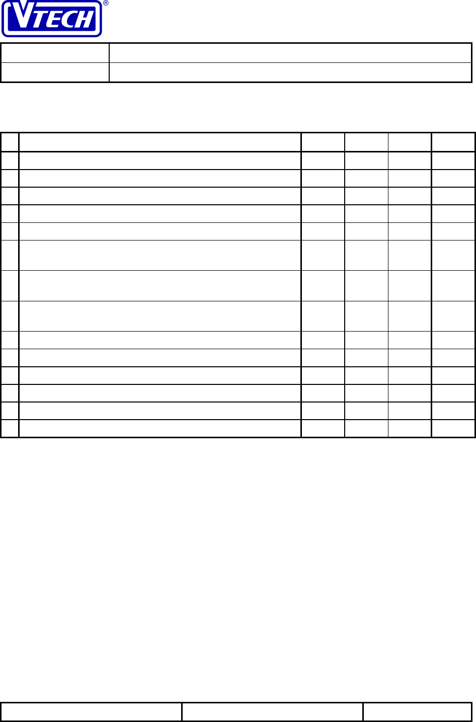
6.4 Telephone Line Interface Specifications
Specifications marked with * are guaranteed at the nominal testing temperature and voltage on
all units with the use of automated production test equipment (ATE)
Parameter Min Typ Max Units
* DTMF Frequency Tolerance -1.5 +1.5 %
* DTMF Low Group Tone Level1-7.5 -5.0 -4.0 dBm
* DTMF High Group Tone Level1-5.5 -3.0 -2.0 dBm
DTMF Combined Tone Level1+2.0 dBm
DTMF High Group Preemphasis (Twist) 2.0 4.0 dB
Pulse Dialling Break Duration 60 ms
Pulse Dialling Make Duration 40 ms
Pulse Dialling Rate 10 pps
Ring Detection Frequency2,3 15 68 Hz
Ring Response Voltage340 Vrms
Ring No-Response Voltage415 Vrms
Notes: 1. Measured across a 900Ω terminating impedance
2. The ringer must ring with signals within this range
3. Measured with a frequency of 20Hz
4. The ringer must not ring with signals within this range
VTECH ENGINEERING CANADA LTD.
TITLE Product Specification
MODEL VTH1930 (Wireless Headset Phone)
Reference: PRC 00B6 Revision: 0 Page: 30 of 31
This document is proprietary to VTECH ENGINEERING CANADA LTD.
Specifications are preliminary and are subject to change without notice. 21146
6.5 Radio Specifications
Specifications marked with * are guaranteed at the nominal testing temperature and voltage on
all units with the use of automated production test equipment (ATE)
Parameter Min Typ Max Units
Number of RF Duplex Channels110 -
Duplex Frequency 22.75 MHz
RF Channel Spacing 300 kHz
RF Bandwidth2150 kHz
IF Frequency 10.70 MHz
Base Unit Transmission Frequency 902.3
0905.0
0MHz
Headset Transmission Frequency 925.0
5927.7
5MHz
Transmitter Frequency Stability (over temperature
range) -10 +10 kHz
* Base FSK Peak Deviation - Data 40 50 60 kHz
* Headset FSK Peak Deviation - Data 40 50 60 kHz
* Receiver Sensitivity - 30dB SINAD3-105 -106 dBm
Adjacent Channel Rejection455 dB
Image Rejection465 dB
* Clear Channel Detection Level -100 -80 dBm
Notes: 1. A duplex channel includes 1 base to handset link and 1 handset to base link
2. 3dB bandwidth of IF filter
3. Measured through a CCITT audio weighting filter
4. RF level of desired signal set to provide 25dB SINAD (CCITT); rejection is
relative level of interference signal above desired signal to reduce SINAD to 20dB
(CCITT)
VTECH ENGINEERING CANADA LTD.
TITLE Product Specification
MODEL VTH1930 (Wireless Headset Phone)
Reference: PRC 00B6 Revision: 0 Page: 31 of 31
This document is proprietary to VTECH ENGINEERING CANADA LTD.
Specifications are preliminary and are subject to change without notice. 21146
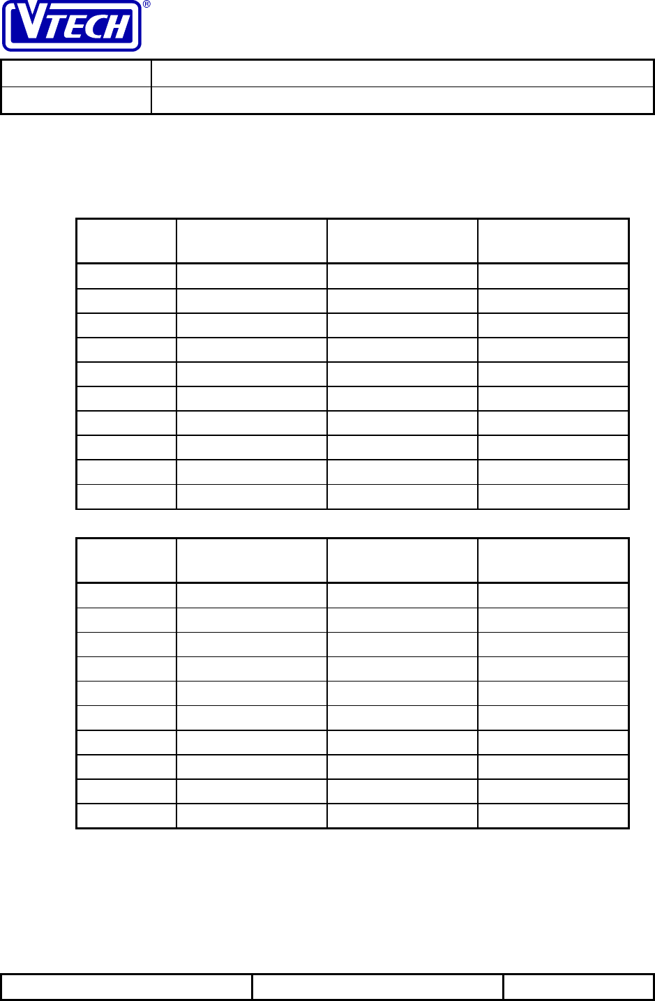
6.6 Frequency Allocation Tables
The RF channels for the 910ADL are allocated in fixed pairs as indicated in the tables below.
The duplex frequency is maintained at a fixed 22.75MHz for all 10 channels.
6.6.1 Base Unit Frequencies
Channel # Transmit
Frequency Receive
Frequency Rx LO Frequency
1 902.30 MHz 925.05 MHz 914.35 MHz
2 902.60 MHz 925.35 MHz 914.65 MHz
3 902.90 MHz 925.65 MHz 914.95 MHz
4 903.20 MHz 925.95 MHz 915.25 MHz
5 903.50 MHz 926.25 MHz 915.55 MHz
6 903.80 MHz 926.55 MHz 915.85 MHz
7 904.10 MHz 926.85 MHz 916.15 MHz
8 904.40 MHz 927.15 MHz 916.45 MHz
9 904.70 MHz 927.45 MHz 916.75 MHz
10 905.00 MHz 927.75 MHz 917.05 MHz
6.6.2 Headset Frequencies
Channel # Transmit
Frequency Receive
Frequency Rx LO Frequency
1 925.05 MHz 902.30 MHz 913.00 MHz
2 925.35 MHz 902.60 MHz 913.30 MHz
3 925.65 MHz 902.90 MHz 913.60 MHz
4 925.95 MHz 903.20 MHz 913.90 MHz
5 926.25 MHz 903.50 MHz 914.20 MHz
6 926.55 MHz 903.80 MHz 914.50 MHz
7 926.85 MHz 904.10 MHz 914.80 MHz
8 927.15 MHz 904.40 MHz 915.10 MHz
9 927.45 MHz 904.70 MHz 915.40 MHz
10 927.75 MHz 905.00 MHz 915.70 MHz