VTech Telecommunications 80-5348-00 VTech 5825 & 5850 User Manual Important Safety Instructions

VTech Telecommunications Ltd VTech 5825 & 5850 Important Safety Instructions

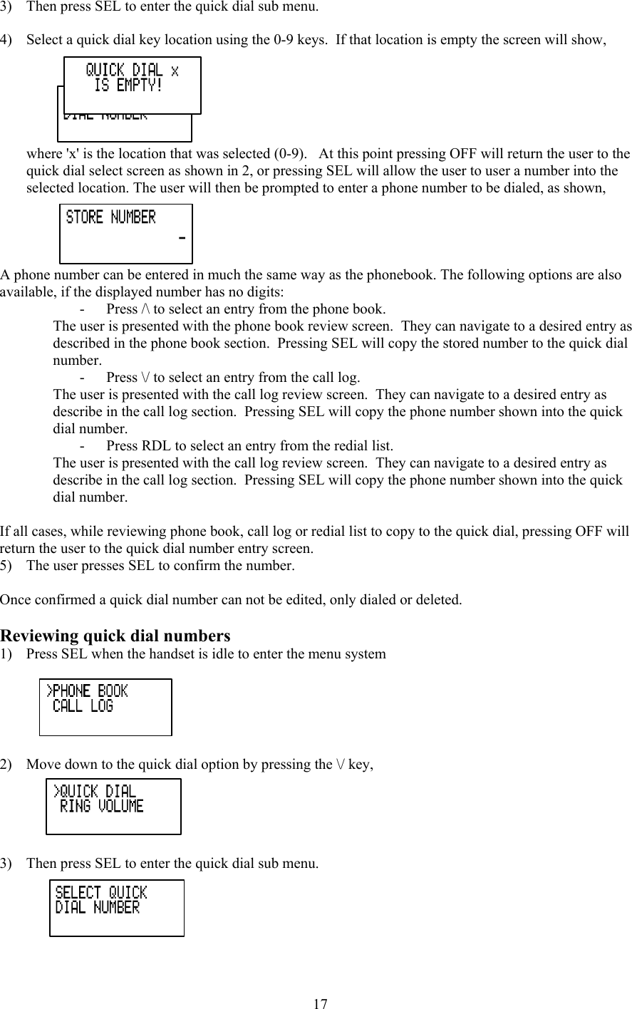
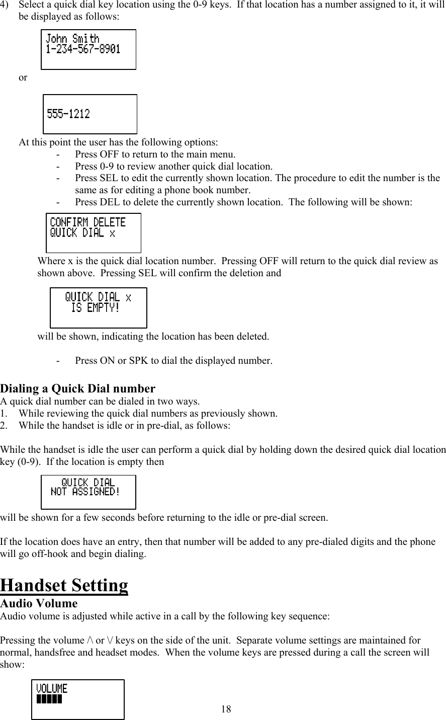
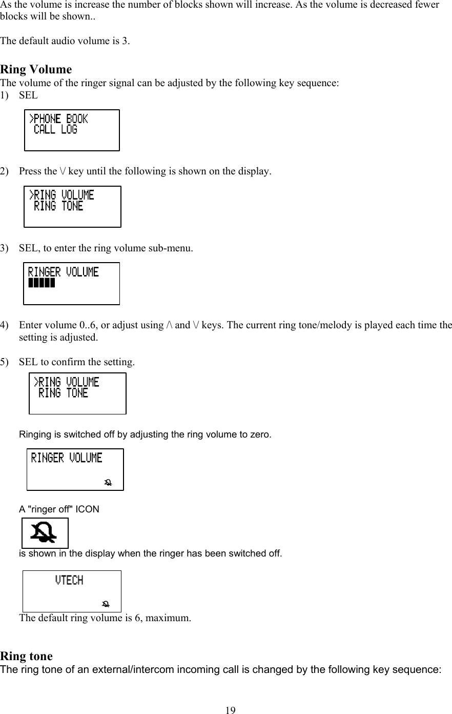
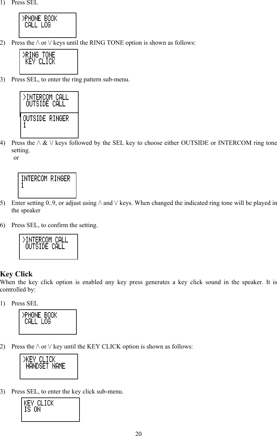
5825 draft manual without caution

Important Safety Instructions  When using your telephone equipment, basic safety precautions should always be followed to reduce the risk of fire, electric shock and injury, including the following: 1. Read and understand all instructions. 2. Follow all warnings and instructions marked on the product. 3. Unplug this product from the wall outlet before cleaning. Do not use liquid cleaners or aerosol cleaners. Use a damp cloth for cleaning. 4. Do not use this product near water (for example, near a bath tub, kitchen sink, or swimming pool). 5. Do not place this product on an unstable cart, stand, or table. The product may fall, causing serious damage to the product. 6. Slots and openings in the cabinet and the back or bottom are provided for ventilation. To protect it from overheating, these openings must not be blocked by placing the product on the bed, sofa, rug, or other similar surface. This product should never be placed near or over a radiator or heat register. This product should not be placed in a built-in installation where proper ventilation is not provided. 7. This product should be operated only from the type of power source indicated on the marking label. If you are not sure of the type of power supply to your home, consult your dealer or local power company. 8. Do not allow anything to rest on the power cord. Do not locate this product where the cord will be abused by persons walking on it. 9. Never push objects of any kind into this product through cabinet slots as they may touch dangerous voltage points or short out parts that could result in a risk of fire or electric shock. Never spill liquid of any kind on the product. 10. To reduce the risk of electric shock, do not disassemble this product. Opening or removing cabinet parts other than specified access doors may expose you to dangerous voltages or other risks. Incorrect  eassembling can cause electric shock when the appliance is subsequently used. 11. Do not overload wall outlets and extension cords as this can result in the risk of fire or electric shock. 12. Unplug this product from the wall outlet and contact VTECH under the following conditions: A. When the power supply cord or plug is damaged or frayed. B. If liquid has been spilled into the product. C. If the product has been exposed to rain or water. D. If the product does not operate normally by following the operating instructions. Adjust only those controls that are covered by the operating instructions, because improper adjustment of other controls may result in damage and will often require extensive work to restore the product to normal operation. E. If the product has been dropped and the cabinet has been damaged. F. If the product exhibits a distinct change in performance. 13. Avoid using a telephone (other than a cordless type) during an electrical storm. There may be a remote risk of electric shock from lightning. 14. Do not use this or any cordless telephone to report a gas leak in the vicinity of the leak.  VTECH COMMUNICATIONS INC. CUSTOMER SERVICE : 1-800-595-9511. In Canada, call VTech Electronics Ltd. At 1-800-267-7377.   BEFORE USING YOUR ip 5825 SYSTEM, CAREFULLY PEEL OFF THE PROTECTIVE FILM, COVERING THE DISPLAYS.   SAVE THESE INSTRUCTIONS       1
Introduction The ip 5825 is an advanced cordless telephone that operates in the 5.8GHz frequency range. Your ip 5825 is capable of supporting up to a maximum of 2 Handsets.  This manual is designed to familiarize you with the ip 5825 cordless telephone. We strongly recommend you read the manual before using your phone.  STOP!! If you have questions about this product, or if you’re having difficulty with setup or operation, do not return your phone to the store. Call our Customer Support Center at 1-800-595-9511 In Canada, call 1-800-267-7377                               2
Parts Check List  1. Base Unit  6. Belt Clip 2. Handset  7. Base Wall Mounting Bracket 3. Handset Charger  8. Charger Wall Mounting Bracket 4. Base AC Power Adapter  9. Owner’s Manual 5. Telephone Line Cord  10. Battery Cells     To purchase replacement battery cells, call VTech Communications Inc. at 1-800-595-9511. In Canada, call VTech Electronics Ltd. at 1-800-267-7377.                 Placing the parts here which including in GB                             3
The Handset Layout               Place the HS here with relative call-outs                    1. Antenna 2. Volume Control 3. Soft Keys 4. CID 5. Select (Menu) 6. On (Flash) 7.  Dialing Keys (0-9, *, #) 8. Redial (Pause) 9. Mute (Delete) 10. Speakerphone 11. LCD Display 12.  Headset jack (2.5mm) 13. Phonebook 14. Off (Clear) 15. Intercom        4
The Base Unit Layout                Place the Base here with relative call-outs                    1.  In Use LED 2. Charging LED 3. Message Waiting LED 4. Page key           5
Setup  Connecting power to Base Unit/Handset Charger 1.  Plug the AC power adapter into an electrical outlet, and the DC connector into the bottom of the Base Unit.     Place Base illustration here        2. Choose the location for your Handset Charger, and plug its power supply into an electrical outlet.     Place charger illustration here       Installation of Battery Cells in Handset       Place the illustration showing the step of installation of battery cells  Follow the steps below:  1. Remove the battery cover by pressing on the indent and sliding downward. 2. Place the new battery cells in the Handset with the positive and negative poles aligned in the battery compartment. 3. Replace the battery cover by sliding it upwards. 4. If the new battery cells are not already charged, place the Handset in its Charger, and allow it to charge for 12 hours. After initial charge, a maintenance charge of 8 hours should be sufficient.            6
Charging of the Handset Battery Cells  The Handset of your ip 5825 cordless telephone is powered by a rechargeable battery cells. It charges automatically whenever the Handset is in its charger. You should charge the battery pack for 12 hours when you first receive your phone. You’ll know the battery pack needs charging when:  • The low battery message is displayed :  • The Handset seems completely dead, the LCD is completely clear and does not activate when you press the keys.  Place the LOW BATT LCD here   IMPORTANT: 1.  Do not dispose of battery cell in a fire, the cell may explode. 2.  Do not open or mutilate the battery cell. Toxic substances may be released, causing harm to eyes or skin. 3.  Exercise care in handling battery cell in order to prevent an accidental short of the charge contacts, potentially causing the battery pack to overheat. 4.  Do not dispose of this battery cell into household garbage. Please refer to the information concerning proper battery recycling. 5.  Do not charge the battery cell with other electrical device.   Connecting to phone line   Plug one end of the telephone line cord into the jack on the back of the Base Unit. Plug the other end of this cord into the wall jack.   Place the illustration showing connection between base and wall jacl   Checking for dial tone  After the battery is charged, press ON on the Handset.  The Phone icon will appear on the Handset display, and you will hear dial tone. If not, see In Case of Difficulty.  Tone/Pulse selection Your ip 5825 is preset for tone dialing. See BASE SETTINGS for details.   (place ‘!’ inside a triangle) CAUTION: Use only the VTech power supply provided with your telephone.  IMPORTANT: FOR MAXIMUM PERFORMANCE OF YOUR CORDLESS TELEPHONE SYSTEM: 1. Choose a central location for your Base Unit. 2. Install your Base Unit and Extension Handsets way from electronic equipment, such as personal computers, television sets and microwave ovens. 3. In locations where there are multiple cordless telephones, separate base units as much as possible. 4. Install your telephone equipment away from heat sources and sunlight. 5. Avoid excessive moisture, dust or extreme cold.      7
Wall Mounting  The Wall Mount brackets are designed for use on standard wall mount plates only. Wall mounting is optional. 1. Plug the AC adapters into an electrical outlet, and the DC connector to the bottom of the Base Unit. 2. Connect the telephone line cord to the jack on the bottom of the Base Unit, and the other end to the wall jack. 3. Line up the tabs on the wall mount adapters with the holes on the bottom of the Base Unit/back of the Handset Charger. Snap the wall mount bracket firmly in place. 4. Mount the Base Unit/Handset Charger on the wall. Position the Base Unit/Handset Charger so the  mounting studs will fit into the holes on the wall mount bracket. Slide Base Unit/Handset Charger down on the mounting studs until it locks into place.        Place the illustrations of base and charger wall mounting here             Handset and Base Indicators  Handset Icons  Icon Description    Place all relative icons in this column       Place all relative description  Handset LEDs  LED Description    Place all relative icons in this column       Place all relative description  8
Base Unit Icons  Icon Description    Place all relative icons in this column       Place all relative description  Base LEDs  LED Description    Place all relative icons in this column       Place all relative description                                     9
Phone Book Operation  The handsets share a common phone book, which is stored in the base station. This means that entries inserted by one handset are available for other handsets, and if one deletes a phone book entry, it will disappear from both handsets. The phone book size will hold 50 entries assuming a name with a maximum length of 16 characters and a 32 digit number. The phone book entries are sorted and presented to the user in alphabetical order.   Names are entered using the numerical keys. Multiple key presses of the dialing digit keys is used to generate characters, see the table 5.2. The cursor moves to the next position if another numerical key is pressed or by pressing the /\ key. The last entered character is deleted by pressing DELETE or \/. The entire name is cleared with a long DELETE key press.   Key  Character versus key press numbers    1 2 3 4 5 6 7 8 9 1  space 1        2  A B C 2 a b C     3  D E F 3 d e F     4  G H I 4 g h I     5  J K L 5  j  k L     6  M N O  6  m  n  O     7  P Q R S 7 p Q r  s 8  T U V 8 t u V    9  W X Y  Z  9  w X  y  z 0  0         *  * ? ! / ( )       #  # ' , - . &       The phone book is entered via the menu, as described below or by pressing the /\ key in idle (quick access key) whereby the handset jumps directly to the phone book search menu.   The phone book is accessed as follows:  1)  Press SEL, to enter the menu.  2)  SEL, to enter the Phone book sub-menu.   Storing a new entry 1)  Press the /\ key in idle, or scroll through the sub-menu with the /\ and \/ keys and press SEL with "STORE" in the first line.  2)  If the phone book is full the screen will show,  10
 3)  If the phone book is not full, the user will be prompted to enter the phone number to be stored as shown below:  4)  Enter the number, up to 32 digits.  Note a number MUST be entered.  Refer to the number edit section for more information about key operation in this mode.   In cases the number exceeds 16 digits, the top line will be used to show the entire number.   5)  Press SEL to confirm the number.  If there is no number, the user can not proceed to the next step.  If there is duplicate number in the phone book, the screen will show,  and the user will remain in the store number screen.  If the number is unique the user will move to the name entry screen, 6) Enter the associated name. Refer to the name edit section for more information about key operation in this mode.  7)  Press SEL to confirm the name. A name must be entered, if a name not entered, the user can not proceed to the next step. Unlike phone numbers duplicate names are allowed. The record is stored in the phone book and the record is shown in the phone book review mode.   11
The user can press CLEAR to return to the phone book operation screen, which will show the last operation:   Dialing from the phone book A number can be recalled and dialed from the phone book by: 1)  Press the /\ key in idle, or scroll through the sub-menu with the /\ & \/ keys and press SEL with "REVIEW" in the first line.  The first phone book entry will be shown.  2)  Scroll through the phone book entries using /\ and \/ keys or enter first character of the name to be searched (using the dial digit keys) and continue navigating using the /\ or \/ as scroll keys, until you reach the entry to be dialed.  3)  Press ON or SPK, to dial the number.    Editing a phone book entry 1)  Press the /\ key in idle, or scroll through the sub-menu with the /\ & \/ keys and press SEL with "REVIEW" in the first line.  2)  Scroll through the phone book entries using /\ and \/ keys or enter first character of the name to be searched (using the dial digit keys) and continue navigating using the /\ or \/ as scroll keys, until you reach the entry to be edited.  3)  Press SEL to enter number edit mode   4)  Edit the number as required, using the following options:  12
 When editing or storing a number the user may do any of the following: -  Enter a digit by pressing 0-9, -  Enter a pause by holding REDIAL, -  Delete a digit by pressing DELETE, -  Delete the entire string by holding DELETE, -  Position the cursor to another location by pressing /\ or \/, -  Insert a number from the redial list by pressing REDIAL.  5)  Press SEL to confirm the number and enter name edit mode.   6)  Edit the name as required, using the following options:  -  Enter characters using the keys 0-9, * and # (See previous character entry table), -  Press DELETE to delete the character under the cursor, or to the left if at the end of the string. -  Hold DELETE to delete the entire string, -  Press /\ and \/ to position move to another character  7)  Press SEL to confirm change.    Delete a phone book entry 1)  Press the /\ key in idle, or scroll through the sub-menu with the /\ & \/ keys and press SEL with "REVIEW" in the first line.  2)  Scroll through the phone book entries using /\ and \/ keys or enter first character of the name to be searched (using the dial digit keys) and continue navigating using the /\ or \/ as scroll keys, until you reach the entry to be removed.  3)  Press DELETE to delete the entry. The phone returns to the previous entry,  or the next entry if the first entry was the entry that was deleted.   Additional note on long phone numbers.  13
When reviewing the phone book the second line of the display will display phone number up to 16 digits, on a formatted presentation.  For numbers larger than 16 digits only the last 13 digits will be displayed, as shown in the following example:  The "<*" indicates there are additional digits to the left, and the * key can be pressed to scroll the display over to see them.    "<" and ">" indicate additional digits of the left or right side respectively, and the keys "*" or "#" can be used to scroll the phone number to see the additional digits,     Calls Log (Caller ID) All incoming calls with valid caller ID number are stored in a call log. Name and time/date information is also stored in the call log if the central office sends it out.  The number of entries stored in the call log is indicated in idle mode:  The number of unanswered calls (new), if any, is indicated:  The new call indication is removed when all calls in the call log have been reviewed. The NEW icon indicates, in all screens, that there are new calls log entries that have not been reviewed. The call log is entered via the menu, as described below or by pressing the \/ key in idle (quick access key) whereby the handset jumps directly to the call log review.  The call log is reviewed as follows:   1)  SEL, to enter the menu.  14
 2)  Press \/ to get to the call log option  3)  SEL, to enter the Call log sub-menu. 4)  The caller name is shown in the first line of the display, and the number in the second line. If time and date information is contained in the CID and there are three lines in the display, it is shown in the third line. The name contained in the received CID is replaced by the name in the phone book, if the phone book contains a matching number, i.e. the phone book name takes precedence.   5)  Scroll through the call log entries using /\ and \/ keys.   The following actions are possible from the call log: -  Dialing the caller displayed by pressing the ON or SPK keys. -  Deleting the caller displayed by pressing the DELETE key. The phone returns to call log review. -  Deleting all entries in the call log by pressing long DELETE. After this the user will be asked for confirmation and he can either accept the deletion with SEL (= yes) or cancel it with OFF (= no).   If the user presses SEL, all entries in the call log will be deleted and the handset indicates the call log is empty and then returns to the idle state. If the user selects OFF, the phone returns to the last viewed entry. -  Storing the caller displayed in the phone book by pressing the SEL key. If the call log entry has a name and a number it will be added to the phone book and the screen will show:  Before returning the call log entry. If the phone number already exists in the phone book, the entry will not be stored, and the screen will show:   15
 If there is no room in the phone book for the new entry, the display will show:  If the call log entry is missing a name or number, the user will be prompted to enter one before the item is stored in the phone book.  If both a name and number is missing, for example as in a private listing, the request will be rejected with the message:  -  Exiting the call log review by pressing the OFF key. -  ‘!’-character in the right hand side of the first line indicates that the call has not previously been reviewed. The ‘!’-character is cleared when stepping to the next entry in the log or when leaving the call log.   -  The maximum length of the name shown in the first line is 16 characters. If the name as received is longer, only the first 16 characters will be seen. -  The incoming calls are sorted by the order of arrival; the latest is shown first.  Calls from the same number will each have separate call log entries.   If the call log is full, the oldest entry is deleted to make room for the new call. If the call log is empty when the user tries to enter to Call log review, a message the following message is displayed:  It is possible to change the number format in the call log before storing the name/number in the phone book or dialing the caller. Pressing the ’#’ key will toggle the number format. The available number formats depend on the number of digits received number.   Quick Dialing Up to 10 'quick dial 'numbers may be entered into each handset.  It is possible to 'quick dial' numbers with just a single key press.  The quick dial list in each handset is unique to that handset and is not shared with the other handset.  Entering a Quick Dial number 1)  Press SEL when the handset is idle to enter the menu system  2)  Move down to the quick dial option by pressing the \/ key,   16
3)  Then press SEL to enter the quick dial sub menu.  4)  Select a quick dial key location using the 0-9 keys.  If that location is empty the screen will show, where 'x' is the location that was selected (0-9).   At this point pressing OFF will return the user to the quick dial select screen as shown in 2, or pressing SEL will allow the user to user a number into the selected location. The user will then be prompted to enter a phone number to be dialed, as shown, A phone number can be entered in much the same way as the phonebook. The following options are also available, if the displayed number has no digits: -  Press /\ to select an entry from the phone book. The user is presented with the phone book review screen.  They can navigate to a desired entry as described in the phone book section.  Pressing SEL will copy the stored number to the quick dial number. -  Press \/ to select an entry from the call log. The user is presented with the call log review screen.  They can navigate to a desired entry as describe in the call log section.  Pressing SEL will copy the phone number shown into the quick dial number. -  Press RDL to select an entry from the redial list. The user is presented with the call log review screen.  They can navigate to a desired entry as describe in the call log section.  Pressing SEL will copy the phone number shown into the quick dial number.  If all cases, while reviewing phone book, call log or redial list to copy to the quick dial, pressing OFF will return the user to the quick dial number entry screen. 5)  The user presses SEL to confirm the number.  Once confirmed a quick dial number can not be edited, only dialed or deleted.  Reviewing quick dial numbers 1)  Press SEL when the handset is idle to enter the menu system  2)  Move down to the quick dial option by pressing the \/ key,  3)  Then press SEL to enter the quick dial sub menu.   17
4)  Select a quick dial key location using the 0-9 keys.  If that location has a number assigned to it, it will be displayed as follows: or At this point the user has the following options: -  Press OFF to return to the main menu. -  Press 0-9 to review another quick dial location. -  Press SEL to edit the currently shown location. The procedure to edit the number is the same as for editing a phone book number. -  Press DEL to delete the currently shown location.  The following will be shown: Where x is the quick dial location number.  Pressing OFF will return to the quick dial review as shown above.  Pressing SEL will confirm the deletion and will be shown, indicating the location has been deleted.  -  Press ON or SPK to dial the displayed number.  Dialing a Quick Dial number A quick dial number can be dialed in two ways. 1.  While reviewing the quick dial numbers as previously shown. 2.  While the handset is idle or in pre-dial, as follows:  While the handset is idle the user can perform a quick dial by holding down the desired quick dial location key (0-9).  If the location is empty then will be shown for a few seconds before returning to the idle or pre-dial screen.  If the location does have an entry, then that number will be added to any pre-dialed digits and the phone will go off-hook and begin dialing.  Handset Setting Audio Volume Audio volume is adjusted while active in a call by the following key sequence:   Pressing the volume /\ or \/ keys on the side of the unit.  Separate volume settings are maintained for normal, handsfree and headset modes.  When the volume keys are pressed during a call the screen will show:  18
 As the volume is increase the number of blocks shown will increase. As the volume is decreased fewer blocks will be shown..  The default audio volume is 3.  Ring Volume The volume of the ringer signal can be adjusted by the following key sequence:  1) SEL  2)  Press the \/ key until the following is shown on the display.  3)  SEL, to enter the ring volume sub-menu.  4)  Enter volume 0..6, or adjust using /\ and \/ keys. The current ring tone/melody is played each time the setting is adjusted.   5)  SEL to confirm the setting.   Ringing is switched off by adjusting the ring volume to zero.   A "ringer off" ICON  is shown in the display when the ringer has been switched off.  The default ring volume is 6, maximum.    Ring tone The ring tone of an external/intercom incoming call is changed by the following key sequence:   19
1) Press SEL 2)  Press the /\ or \/ keys until the RING TONE option is shown as follows: 3)  Press SEL, to enter the ring pattern sub-menu.  4)  Press the /\ & \/ keys followed by the SEL key to choose either OUTSIDE or INTERCOM ring tone setting. or   5)  Enter setting 0..9, or adjust using /\ and \/ keys. When changed the indicated ring tone will be played in the speaker  6)  Press SEL, to confirm the setting.  Key Click When the key click option is enabled any key press generates a key click sound in the speaker. It is controlled by:   1) Press SEL  2)  Press the /\ or \/ key until the KEY CLICK option is shown as follows:  3)  Press SEL, to enter the key click sub-menu.  20
 4)  Enable key click by pressing 1 or/\, or disable key click by pressing the 0 or \/ key.  5)  Press SEL, to confirm the setting.  Key click is enabled by default.  Handset Name It is possible to gives each handset its' own unique name. The name is shown in the first line during idle replacing the "VTECH" normally shown during idle.  The name is strictly local, is not used within the system to address handsets and purely cosmetic.  The name can be a maximum of 16 characters in length.  The handset naming procedure is as follows:   1) Press SEL  2)  Press the /\ or \/ keys until the HANDSET NAME option is shown as follows:  3)  Press SEL, to enter the handset name sub-menu.  4)  Enter handset name (characters are entered in the same way as for the phone book).  5)  Press SEL, to confirm the setting.  When returning to idle the display shows:  21
 Language The language used in the actual handset can be selected by the following sequence:  1) Press SEL  2)  Press the /\ or \/ keys until the LANGUAGE option is shown as follows:  3)  Press SEL, to enter the language selection sub-menu. The current language is shown in the second line. Select Spanish, French or English by pressing /\ or \/ key.  4)  Press SEL, to confirm the setting. The phone returns to the previous menu.  The display texts in three languages (English, Spanish and French) are stored in the handset ROM. There is an EEPROM parameter in the handset, which tells, which language is selected. Default value is English, but the language can be changed to Spanish or French during production by programming the EEPROM parameter.   Clear Message waiting The Message waiting indication can be removed from the display by the following sequence:  1) Press SEL  2)  Press the /\ or \/ keys until the CLR MSG WAITING option is shown as follows:  3)  Press SEL, to enter the message sub-menu.   22
 4)  Confirm clearing of the message waiting indication by pressing SEL (= yes), or cancel clearing by pressing OFF (= no). After this the phone returns to the previous menu.  Dial Method It is possible change the method of dialing between DTMF and pulse dialing if the CO supports pulse dialing.   1) Press SEL  2)  Press the /\ or \/ keys until the DIAL TYPE option is shown as follows:  3)  Press SEL, to enter the dial sub-menu.  4)  Press the /\ or \/ to choose the method of dialing , the display looks like the one below  5)  Alternately the user can select pulse dialing by pressing 1 or /\. Select DTMF dialing by pressing the 0 or \/.  6)  Press SEL to confirm the setting.  The default dial method is DTMF.   When the phone is in pulse dial mode, it is possible to switch to temporary DTMF mode during an ongoing call by pressing the key *.  Once pressed DTMF will be used for the rest of that particular external call.       23
Handset Operation Making Calls   • Press ON  (or,  SPEAKERPHONE  to use the Handset Speakerphone feature). Dial the phone number. -OR- • Dial the phone number first; then press ON  (or SPEAKERPHONE).  • Press OFF to end your call   Place the Handset here with circling the ON or Speakerphone key   Answering Calls  From the Handset • Press any key except OFF and the softkeys.  • Press OFF to end your call.    Place the Handset here with circling the OFF key   Intercom Call Pressing INT key when the handset is idle initiates an intercom call.  - Press INT  The call is performed and when the other handset answers, the display will change to:  If the other handset is out of range, turned off or on an external call, the display will show and a busy tone will be heard on the earpiece, or through the speaker if in handsfree mode.  An intercom call is terminated by: -  Pressing OFF or INT, -  Placing the handset in the charger  After terminating an INTERCOM CALL, the display on both handsets will show: On the handset that did not terminate the call a busy tone will be heard in the indicating the other  24
handset has ended the call.  After several seconds the display will return to idle and the busy tone will stop.  Call Forward & Call Transfer An external call can be forwarded or transferred from one handset to the other handset.  The difference between forward and transfer depends on if the sending handset needs to talk with the receiving handset, before the external call is actually sent to the other handset.  Call Forward A handset on an external call can forward it to the other handset by holding the INT key.   The display will initially show:   If the base can connect to the other handset, the display will change to:   And then return to the idle display.   If the base can not find the other handset as a result of it being out of range or powered off, the display will show:    And the external will 'call back' to the handset.  Call Transfer An external call is transferred by: 1.  Press INT key (the external call is put on hold) 2.  Destination handset will ring, showing an intercom call. 3.  Pressing the ON key on the destination handset will answer the intercom call. 4.  Discussing external call with other handset 5.  Press OFF, on the first handset, to transfer external call to other handset  If there is no answer on the destination handset, the first handset can reconnected to the held call by pressing INT to reconnect to the external call.  Call Back After forwarding a call, a CALL BACK is generated in the forwarding handset if the forwarded call is not answered within a timeout of 30 seconds. When a call is returned to a handset it will show the following while ringing:    25
If the returned call is not answered within 30 seconds, the phone automatically goes on hook, dropping the external call.  Conference It is possible to establish a conference between two handsets and the external line.  If a handset already has a connection to the external line, and another handset goes off-hook, a conference is immediately established.  Both handsets will show:   Both handsets connected to the external line are allowed to transmit DTMF digits / dialing pulses to the line.   If a handset is on the process of transferring a call to the other handset it is possible to conference with both calls by holding the INT key.  Holding INT with connected to either party, when transferring, or call toggling, will immediately conference both handsets and external line.  A handset can leave the conference by going on-hook, by pressing OFF, or placing the handset on the base or charging cradle. The connection continues between the remaining handset and the external party.  Redial at On-Hook state Pressing REDIAL while the handset is idle or pre-dialing will access the last dialed number.  Subsequent presses of REDIAL will access previously dialed numbers.  After the fifth number the redial list will cycle back to the most recently dialed number.  Alternately the user can user the /\ and \/ keys to scroll through the 5 previously dialed numbers.  Pressing OFF will cancel the redial list review.  Pressing ON or SPK will add the shown redial number to any pre-dialed digits, go off-hook and start dialing.  Pressing SEL add just add the shown redial to any pre-dialed digits. . Redial at Off-Hook state Pressing REDIAL when on an external call will display the last dialed number.   After two second the shown number will be automatically dialed.  If during this time, REDIAL is pressed again the display will return to the external call presentation, and the number will not be dialed.  Flash  During an ongoing external call, a flash of 600ms is generated on the line when pressing the FLASH/ON key.  Mute It is possible to mute the microphone during a conversation by pressing the DELETE/MUTE key. The microphone is un-muted by pressing the DELETE/MUTE key again.  In case the external line is muted, when establishing an intercom connection, the line is un-muted automatically after the intercom call is terminated.  The line is also un-muted after a flash (register recall)   26
A text message in the display indicates when the microphone is first muted.    The MUTE icon will also be shown whenever the microphone is muted.  When the muting is disabled a test message on the display will briefly be shown.   And the MUTE icon will turn off.  Page The page call function is used as an aid to locate the handsets.  It can be only done from the base.  To activate paging the user presses the PAGE button on the base.  All handsets not currently active in a call will show: and start the paging sound.  Any handset that showing this display can cancel the paging by pressing any of the PHONE, 0-9, *, # or SPK keys.  A second press of the base PAGE button can also cancel paging.         27
Headset Operation  Your ip 5825 cordless telephone is equipped with a 2.5mm Headset Jack for use with an optional accessory Headset for hands-free operation. If you choose to use the Headset option, you must obtain an optional  accessory Headset, which is compatible with the ip 5825.  To purchase a Headset, call VTECH Customer Service at 1-800-595-9511.  Once you have a compatible 2.5mm Headset, locate the Headset Jack on the ip 5825 Handset. Connect the plug on the Headset cord to the jack on the cordless Handset. The plug should fit securely. Do not force the connection.      Place the Handset with headset plug-in NOTE : Whenever a compatible Headset is connected to the cordless Handset, the microphone on the Handset will be muted. This is done to limit the effect of background noise. Many compatible headsets have a reversible, monaural design. You can wear your Headset on either ear, leaving one ear free for room conversation.    Place the Handset with belt-clip  Belt Clip  The ip 5825 is also equipped with a detachable belt clip. Align the pins on the inside edge of the clip with the notches on the sides of the ip 5825 Handset. The belt clip should snap securely into place. Do not force the connection.    Maintenance Taking Care Of Your Telephone Your ip 5825 cordless telephone contains sophisticated electronic parts, so it must be treated with care.  Avoid rough treatment Place the Handset down gently. Save the original packing materials to protect your telephone if you ever  need to ship it.  Avoid water Your telephone can be damaged if it gets wet. Do not use the Handset outdoors in the rain, or handle it with wet hands. Do not install your Base Unit near a sink, bathtub or shower.  Electrical storms Electrical storms can sometimes cause power surges harmful to electronic equipment.  For your own safety, use caution when using electric appliances during storms.  Cleaning your telephone Your telephone has a durable plastic casing that should retain its luster for many years.  Clean it only with a soft cloth slightly dampened with water or a mild soap. Do not use excess water or cleaning solvents of any kind.     28
Remember that electrical appliances can cause serious injury if used when you are wet or standing in water. If your Base Unit should fall into water, DO NOT RETRIEVE IT UNTIL YOU UNPLUG THE POWER CORD AND TELEPHONE LINE CORDS FROM THE WALL. Then pull the unit out by the unplugged cords.   In Case Of Difficulty If you have difficulty operating your phone, the suggestions below should solve the problem. If you still have difficulty after trying these suggestions, call VTECH Communications at 1-800-595-9511. In Canada, call VTECH Electronics at 1-800-267-7377.  The Phone Doesn’t Work At All • Make sure the Power Cord is plugged in. • Make sure the telephone line cord is plugged firmly into the Base Unit and the telephone wall jack. • Make sure the batteries are properly charged. If the ‘LOW BATTERY’ message is shown, the battery pack needs charging.  No Dial Tone • First check all the suggestions above. • If you still don’t hear a dial tone, disconnect the Base Unit from the telephone jack and connect a different phone. If there is no dial tone on that phone either, the problem is in your wiring or local service. Contact your local telephone company.  You Get Noise, Static, Or A Weak Signal Even When You’re Near The Base Unit • Household appliances plugged into the same circuit as the Base Unit can sometimes cause interference. Try moving the appliance or the Base Unit to another outlet.  You Get Noise, Static, Or A Weak Signal When You’re Away From The Base Unit • You may be out of range. Either move closer to the Base, or relocate the Base Unit. • The layout of your home may be limiting the range. Try moving the Base Unit to another position.  The Handset Does Not Ring When You Receive A Call • Make sure you have the ringers activated. To set the ringer, see HANDSET SETTINGS  • Make sure the telephone line cord is plugged firmly into the Base Unit and the telephone jack. Make sure the power cord is plugged in. • You may be too far from the Base Unit. • You may have too many extension phones on your telephone line to allow all of them to ring. Try plugging some of the other phones.  You Hear Other Calls While Using Your Phone • Disconnect your Base Unit from the telephone jack, and plug in a regular telephone.  If you still hear other calls, the problem is probably in your wiring or local service. Call your local telephone company.  You Hear Noise In The Handset, And None Of The Keys Or Buttons Work • Make sure the power cord is plugged in.  Common Cure For Electronic Equipment  If the unit does not seem to be responding normally, then try putting the Handset in the cradle. If it does not seem to respond, do the following (in the orderlisted) : 1. Disconnect the power to the Base. 2. Disconnect the Handset battery, and spare battery pack, if applicable. 3. Wait a few minutes. 4. Connect power to the Base. 5. Re-install the battery pack (s) 6.  Watch for Handset to display :  Place the LCD here showing “FOUND BASE”    29
Warranty Statement What does this limited warranty cover? • The manufacturer of this VTECH product, VTECH Communications, warrants to the holder of a valid proof of purchase (“Consumer” or “you”) that the product and all accessories provided by VTECH in the sales package (“Product”) are free from material defects in material and workmanship, pursuant to the following terms and conditions, when installed and used normally and in accordance with operation instructions, This limited warranty extends only to the Consumer for Products purchased and used in the United States of America.  What will VTECH Communications do if the Product is not free from material defects in materials and workmanship during the limited warranty period (“Materially Defective Product”)? • During the limited warranty period, VTECH’s authorized service representative will repair ot replace at VTECH’s option, without charge, a Materially Defective Product.  If we repair this product, we may use new or refurbished replacement parts. If we choose to replace this product, we may replace it with a new or refurbished product of the same or similar design. VTECH will return repaired or replacement products to you in working condition. VTECH will retain defective parts, modules, or equipment. Repair or replacement of Product, at VTECH’s option, is your exclusive remedy. You should expect the repair or replacement to take approximately 30 days.  How long is the limited warranty period? • The limited warranty period for the product extends for ONE(1) YEAR from the date of purchase if we repair or replace a Materially Defective Product under the terms of this limited warranty. This limited warranty also applies to repaired or replacement Products for a period of either (a) 90 days from the date the repaired or replacement Product is shipped to you or (b) the time remaining on the original one-year warranty; whichever is longer.  What is not covered by this limited warranty? This limited warramty does not cover  1. Product that has been subjected to misuse, accident, shipping or other physical damage, improper installation, abnormal operation or handling, neglect, inundation, fire, water or other liquid intrusion; or 2. Product that has been damaged due to repair, alteration or modification by anyone other than an authorized service representative of VTECH; or 3. Product to the extent that the problem experienced is caused by signal conditions, network reliability or cable or antenna systems; or 4.Product to the extent that the problem is caused by use with non-VTECH electrical accessories; or 5.Product whose warranty/quality stickers, Product serial numbers plates or electronic serial numbers have been removed, altered or rendered illegible; or 6. Product purchased, used, serviced, or shipped for repair from outside the united States, or used for commercial or institutional purposes (including but not limited to Products used for rental purposes); or 7. Product returned without vallid proof of purchase (see 2 below); or 8.Charges for installation or set up, adjustment of customer controls, and installation or repair of systems outside the unit.  How do you get warranty service? • To obtain warranty service in the United States of America, call 1 800-595- 9511 for instructions regarding where to return the Product. Before calling for service, please check the user’s manual. A check of the Product controls and features may save you a service call. • Except as provided by applicable law, you assume the risk of loss or damage during transit and transportation and are responsible for delivery or handling charges incurred in the transport of Product(s) to the service location. VTECH will return repaired or replaced product under this limited warranty to you, transportation, delivery or handling charges prepaid. VTECH assumes no risk for damage or loss of the Product in transit. • If the Product failure is not covered by this limited warranty, or proof of purchase does not meet the terms of this limited warranty, VTECH will notify you and will request that you authorize the cost of repair and return shipping costs for the repair of Products that are not covered by this limited warranty.  What must you return with the Product to get warranty service? 1. Return the entire original package and contents including the Product to the VTECH service location along with a description of the malfunction or difficulty;  30
2. Include “valid proof of purchase” (sales receipt) identifying the Product purchased (Product model) and the date of purchase or receipt; and 3. Provide your name, complete and correct mailing address, and telephone number.  Other Limitations • This warranty is the complete and exclusive agreement between you and VTECH. It supersedes all other written or oral communications related to this Product. VTECH provides no other warranties for this product. The warranty exclusively describes all of VTECH’s responsibilities regarding the product.   There are no other express warranties. No one is authorized to make modifications to this limited warranty and you should not rely on any such modification.  State Law Rights: This warranty gives you specific legal rights, and you may also have other rights which vary from state to state.  Limitations: Implied warranties, including those of fitness for a particular purpose and merchantability (an unwritten warranty that the product is fit for ordinary use) are limited to one year from date of purchase. Some states do not allow limitations on how long an implied warranty lasts, so the above limitation may not apply to you.  • In to event shall VTECH be liable for any indirect, special, incidental, consequential, or similar damages(including, but not limited to lost profits or revenue, inability to use the product, or other associated equipment, the cost of substitute equipment, and claims by third parties) resulting from the use of this product, some states do not allow the exclusion or limitation of incidental or consequential damages, so the above limitation or exclusion may not apply to you.   FCC, ACTA and IC Regulations This equipment complies with Parts 15 of the Federal Communications Commission (FCC) rules for the United States. It also complies with regulations RSS210 and CS-03 of Industry and Science Canada. Operation is subject to the following two conditions: (1) this device may not cause interference, and (2) this device must accept any interference, including interference that may cause undesired operation of the device.  A label is located on the underside of the Base Unit containing either the FCC registration number and Ringer Equivalence Number (REN) or the IC registration number and Load Number. You must, upon request, provide this information to your local telephone company.  This equipment is compatible with inductively coupled hearing aids.  Should you experience trouble with this telephone equipment, please contact: VTech Communications Inc CUSTOMER SERVICE. at 1-800-595-9511. In Canada, call VTECH Electronics at 1-800-267-7377. For repair/warranty information. The telephone company may ask you to disconnect this equipment from the line network until the problem has been corrected.  FCC Part 15 Warning: Changes or modifications to this unit not expressly approved by the party responsible for compliance could void the user’s authority to operate the equipment. The equipment has been tested and found to comply with part 15 of the FCC rules.  These limits are designed to provide reasonable protection against harmful interference in a residential installation. This equipment generates, uses and can radiate radio frequency energy and, if not installed and used in accordance with the instructions, may cause harmful interference to radio communications. However, there is no guarantee that interference will not occur in a particular installation. If this equipment does cause harmful interference to radio or television reception, which can be determined by turning the equipment off and on, the user is encouraged to try and correct the interference by one or more of the following measures:  • Reorient or relocate the receiving antenna. • Increase the separation between the equipment and receiver. • Connect the equipment into an outlet or on a circuit different from that to which the receiver is connected. • Consult the dealer or an experienced radio/TV technician for help.   31
FCC Part 68 and ACTA If this equipment was approved for connection to the telephone network prior to July 23, 2001, it complies with Part 68 of the Federal Communications Commission (FCC) rules. If the equipment was approved after that date, it complies with the Part 68 rules and with Technical Requirements for Connection of Equipment to the Telephone Network adopted by the Administrative Council for Terminal Attachments (ACTA). We are required to provide you with the following information.  1. Product identifier and REN information The label on the back or bottom of this equipment contains, among other things, an identifier indicating product approval and the Ringer Equivalence Number (REN). This information must be provided to your local telephone company upon request. For equipment approved prior to July 23, 2001, the product identifier is preceded by the phrase “FCC Reg No.” and the REN is listed separately. For equipment approved after that date, the product identifier is preceded by “US” and a colon (:), and the REN is encoded in the product identifier without a decimal point as the sixth and seventh characters following the colon. For example, the product identifier US:AAAEQ03T123XYZ would indicate an REN of 0.3. The REN is used to determine how many devices you may connect to your telephone line and still have them ring when you are called. In most, but not all areas, the sum of all RENs should be five (5.0) or less. You may want to contact your local telephone company for more information.  2. Connection and use with the nationwide telephone network The plug and jack used to connect this equipment to the premises wiring and the telephone network must comply with the applicable Part 68 rules and technical requirements adopted by ACTA. A compliant telephone cord and modular plug is provided with this product. It is designed to be connected to a  compatible modular jack that is also compliant. An RJ11 jack should normally be used for connecting to a single line and an RJ14 jack for two lines. See Installation Instructions in the user’s manual. This equipment may not be used with Coin Telephone Lines or with Party Lines. If you have specially wired alarm dialing equipment connected to your telephone line, ensure the connection of this equipment does not disable your alarm equipment. If you have questions about what will disable alarm equipment, consult your telephone company or a qualified installer.  3. Repair instructions If this equipment is malfunctioning, it must be unplugged from the modular jack until the problem has been corrected. Repairs to this telephone equipment can only be made by the manufacturer or its authorized agents. For repair procedures, follow the instructions outlined under the Limited Warranty.  4. Rights of the telephone company If this equipment is causing harm to the telephone network, the telephone company may temporarily discontinue your telephone service. The telephone company is required to notify you before interrupting service. If advancenotice is not practical, you will be notified as soon as possible. You will be given the opportunity to correct the problem and the telephone company is required to inform you of your right to file a complaint with the FCC. Your telephone company may make changes in its facilities, equipment, operation, or procedures that could affect the proper functioning of this product. The telephone company is required to notify you if such changes are planned.  5. Hearing aid compatibility If this product is equipped with a corded or cordless handset, it is hearing aid compatible.  6. Programming/testing of emergency numbers If this product has memory dialing locations, you may choose to store police, fire department and emergency medical service telephone numbers in these locations. If you do, please keep three things in mind:  a We recommend that you also write the telephone number on the directory card, so that you can still dial the mergency number manually if the memory dialing feature doesn’t work.   b This feature is provided only as a convenience, and the manufacturer assumes no responsibility for customer reliance upon the memory feature. c Testing the emergency telephone numbers you have stored is not recommended. However, if you do make a call to an emergency number: • You must remain on the line and briefly explain the reason for the call before hanging up. • Programming/testing of emergency numbers should be performed during off-peak hours, such as in the early morning or late evening, when the emergency services tend to be less busy.  IC (Industry Canada)  32
This telephone is registered for use in Canada. The term “IC:” before the radio certification number only signifies that Industry Canada technical  specifications were met.  Notice: This equipment meets the applicable Industry Canada Terminal Equipment Technical Specifications. This is confirmed by the registration number. The abbreviation, IC, before the registration number signifies that registration was performed based on a Declaration of Conformity indicating that Industry Canada technical specifications were met. It does not imply that Industry Canada approved the equipment.  Notice: The Ringer Equivalence Number (REN) for this terminal equipment is 0.1. The REN assigned to each terminal equipment provides an indication of the maximum number of terminals allowed to be connected to a telephone interface. The termination on an interface may consist of any combination of devices subject only to the requirement that the sum of the Ringer Equivalence Numbers of all the devices does not exceed five.Before installing this equipment, users should ensure that it is permissible to be connected to the facilities of the local telecommunications company. The equipment must also be installed using an acceptable method of connection. The customer should be aware that compliance with the above conditions may not prevent degradation of services in some situations. Repairs to certified equipment should be made by an authorized Canadian maintenance facility  designated by the supplier. Any repairs or alterations made by the user to this equipment, or equipment malfunctions, may give the telecommunications company cause to request the user to disconnect the equipment. Users should ensure for their own protection that the electrical ground connections of the power utility, telephone lines and internal metallic water pipe system, if present, are connected together. This precaution may be particularly important in rural areas.  Caution : Users should not attempt to make such connections themselves, but should contact the appropriate electrical inspection authority, or electrician, as appropriate.  Your ip 5825 is designed to operate at the maximum power allowed by the FCC and IC. This means your Handset and Base Unit can communicate only over a certain distance - which will depend on the location of the Base Unit and Handset, weather, and the construction and layout of your home or office.   The RBRC Seal The RBRC Seal on the nickel-metal-hydride battery indicates that VTech Communications, Inc. is voluntarily participating in an industry program to collect and recycle these batteries at the end of their useful lives, when taken out of service within the United States and Canada. The RBRC program provides a convenient alternative to placing used nickel-metal-hydride batteries into the trash or municipal waste,which may be illegal in your area. VTech’s participation in RBRC makes it easy for you to drop off the spent battery at local retailers participating in the RBRC program or at authorized VTech product service centers. Please call 1-800-8-BATTERY  for information on Ni-MH battery recycling and disposal bans/restrictions in your area.VTech’s involvement in this program is part of its commitment to protecting our environment and conserving natural resources.  RBRC is a registered trademark of Rechargeable Battery Recycling Corporation.R   Technical Specifications (this part will change accordingly)  FREQUENCY CONTROL Crystal controlled PLL synthesizer  TRANSMIT FREQUENCY Base : 5744.736 - 5825.952 MHz Handset: 2401.056 - 2482.272 MHz  33
 RECEIVE FREQUENCY Base: 2401.056 - 2482.272 MHz Handset : 5744.736 - 5825.952 MHz  CHANNELS 95 Channels  NOMINAL EFFECTIVE RANGE Maximum power allowed by FCC and IC. Actual operating range may vary according to environmental conditions at the time of use.  SIZE Handset : 193mm x 52mm x 40mm (including antenna) Base : 192mm x 143mm x 91mm Charger: 77mm x 69mm x 54mm  WEIGHT Handset : 138 grams (excluding Battery Pack) Base : 396 grams Charger : 216 grams  POWER REQUIREMENTS Handset : 2.4V 1400mAh NiMH Battery Pack Base : 7 VDC @ 900mA Charger : 6 VDC @ 300mA  MEMORY Speed Dial: 50 Memory locations; up to 32 digits per location CID : Alphanumeric Display 50 Memory locations SPECIFICATIONS ARE TYPICAL AND MAY CHANGE WITHOUT NOTICE.        Table Of Contents  Important Safety Instructions …………………………………………………………………………...  1    Introduction…………………………………………………………………………………………………….  2 Parts Check List……………………………………………………………………………………………….  3 The Handset Layout…………………………………………………………………………………………..  4 The Base Layout………………………………………………………………………………………………  5    Getting Started………………………………………………………………………………………………  6 Setup…………………………………………………………………………………………………………… 6         Connecting power to Base Unit/Handset Charger…………………………………………………..  6  34
        Installation of Battery Cells in Handset……………………………………………………………….  6         Charging of the Handset Battery Cells………………………………………………………………..  7         Connecting to phone line………………………………………………………………………………  7         Checking for dial tone………………………………………………………………………………….   7         Tone/Pulse Selection………………………………………………………………………………….  7    Wall Mounting…………………………………………………………………………………………………  8    Basic Operation………………………………………………………………………………………………  8 Handset and Base Indicators……………………………………………………………………………….  8         Handset Icons………………………………………………………………………………………….  8         Handset LEDs………………………………………………………………………………………….  8         Base Unit Icons………………………………………………………………………………………..  9         Base LEDs………………………………………………………………………………………………  9    Phone Book Operation………………………………………………………………………………………  10         Storing a new entry…………………………………………………………………………………….  10         Dialing from the phone book………………………………………………………………………….  12         Editing a phone book entry……………………………………………………………………………  12         Deleting a phone book entry………………………………………………………………………….  13    Calls Log (Caller ID)…………………………………………………………………………………………  14    Quick Dialing…………………………………………………………………………………………………  16         Editing a Quick Dial Number…………………………………………………………………………  16         Reviewing Quick Dial Number……………………………………………………………………….  17         Dialing a Quick Dial Number…………………………………………………………………………  18    Handset Setting……………………………………………………………………………………………..  18         Audio Volume………………………………………………………………………………………….  18         Ring Voulme…………………………………………………………………………………………..  19         Ring Tone……………………………………………………………………………………………..  19         Key Click………………………………………………………………………………………………..  20         Handset Name………………………………………………………………………………………….  21         Language………………………………………………………………………………………………..  22         Clear Message Waiting………………………………………………………………………………..  22         Dial Method…………………………………………………………………………………………….  23    Advanced Operations……………………………………………………………………………………….  24 Handset Operation…………………………………………………………………………………………..  24          Making Calls…………………………………………………………………………………………….  24          Answering Calls…………………………………………………………………………………………  24          Intercom Call…………………………………………………………………………………………….  24          Call Forward & Call Transfer…………………………………………………………………………..  25                    Call Forward……………………………………………………………………………………..  25                    Call Transfer…………………………………………………………………………………….  25                    Call Back………………………………………………………………………………………….  25                    Conference……………………………………………………………………………………….  26          Redial at On-Hook State………………………………………………………………………………..  26          Redial at Off-Hook State……………………………………………………………………………….  26          Flash……………………………………………………………………………………………………...  26          Mute………………………………………………………………………………………………………  26          Page………………………………………………………………………………………………………  27    Headset  Operation……………………………………………………………………………………………  28    Additional Information………………………………………………………………………………………  28 Maintenance…………………………………………………………………………………………………… 28 In Case of Difficulty…………………………………………………………………………………………….  29 Warranty Statement……………………………………………………………………………………………  30 FCC, ACTA and IC Regulations……………………………………………………………………………..  31  35
The RBRC Seal……………………………………………………………………………………………….. 32 Technical Specifications………………………………………………………………………………………  33   36

Navigation menu