VTech Telecommunications 80-7597-01 WiFi Gateway User Manual 1
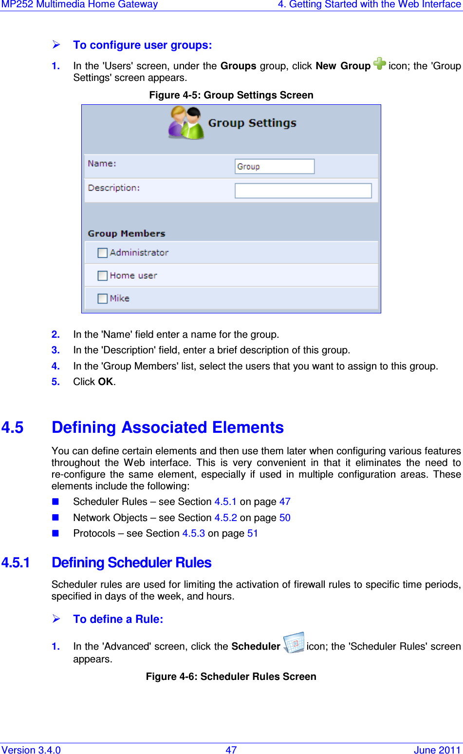
VTech Telecommunications Ltd WiFi Gateway 1
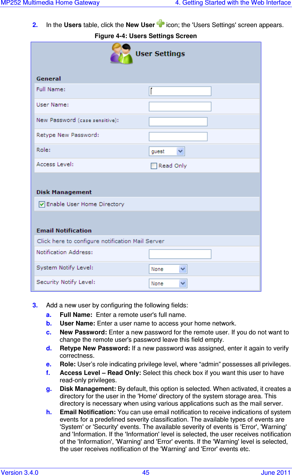
UserManual.wiki
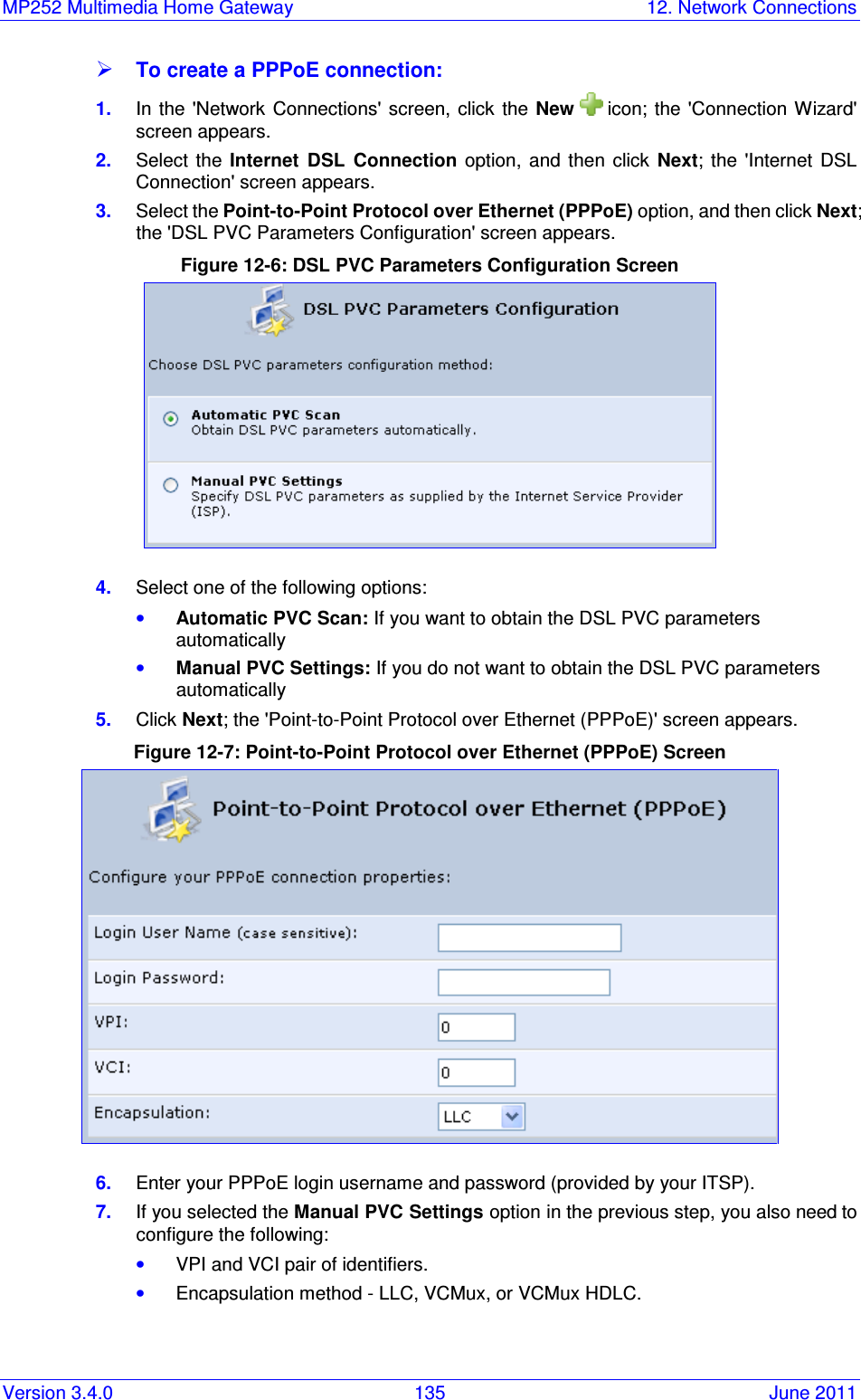
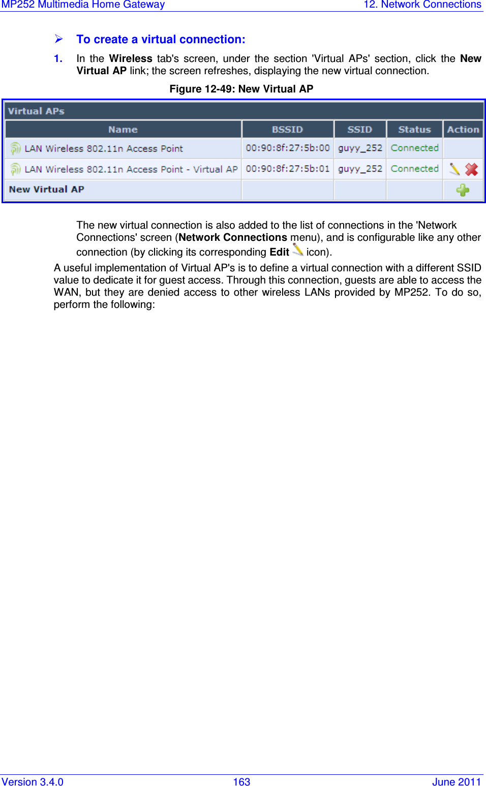
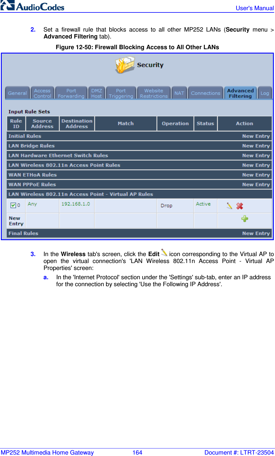
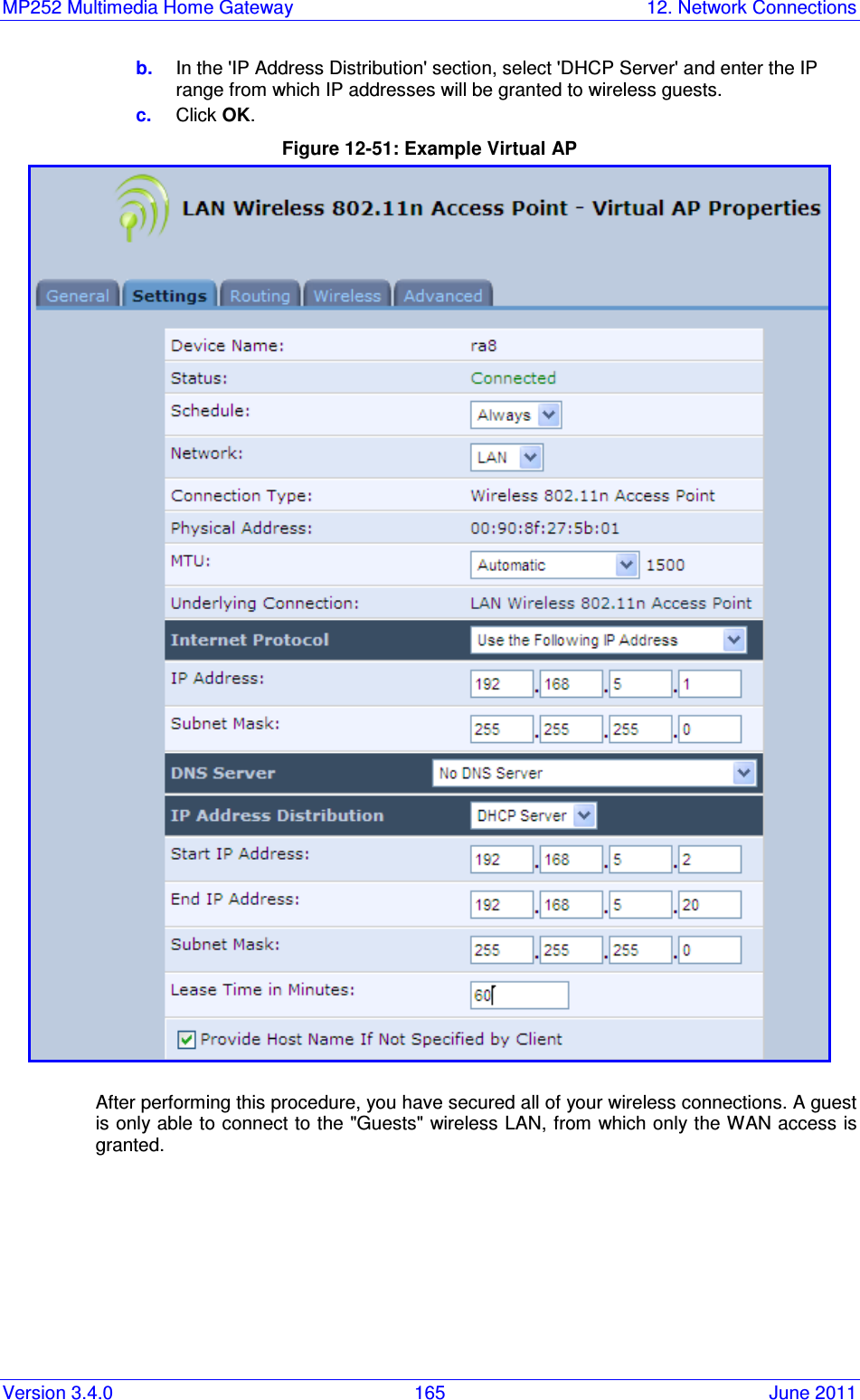
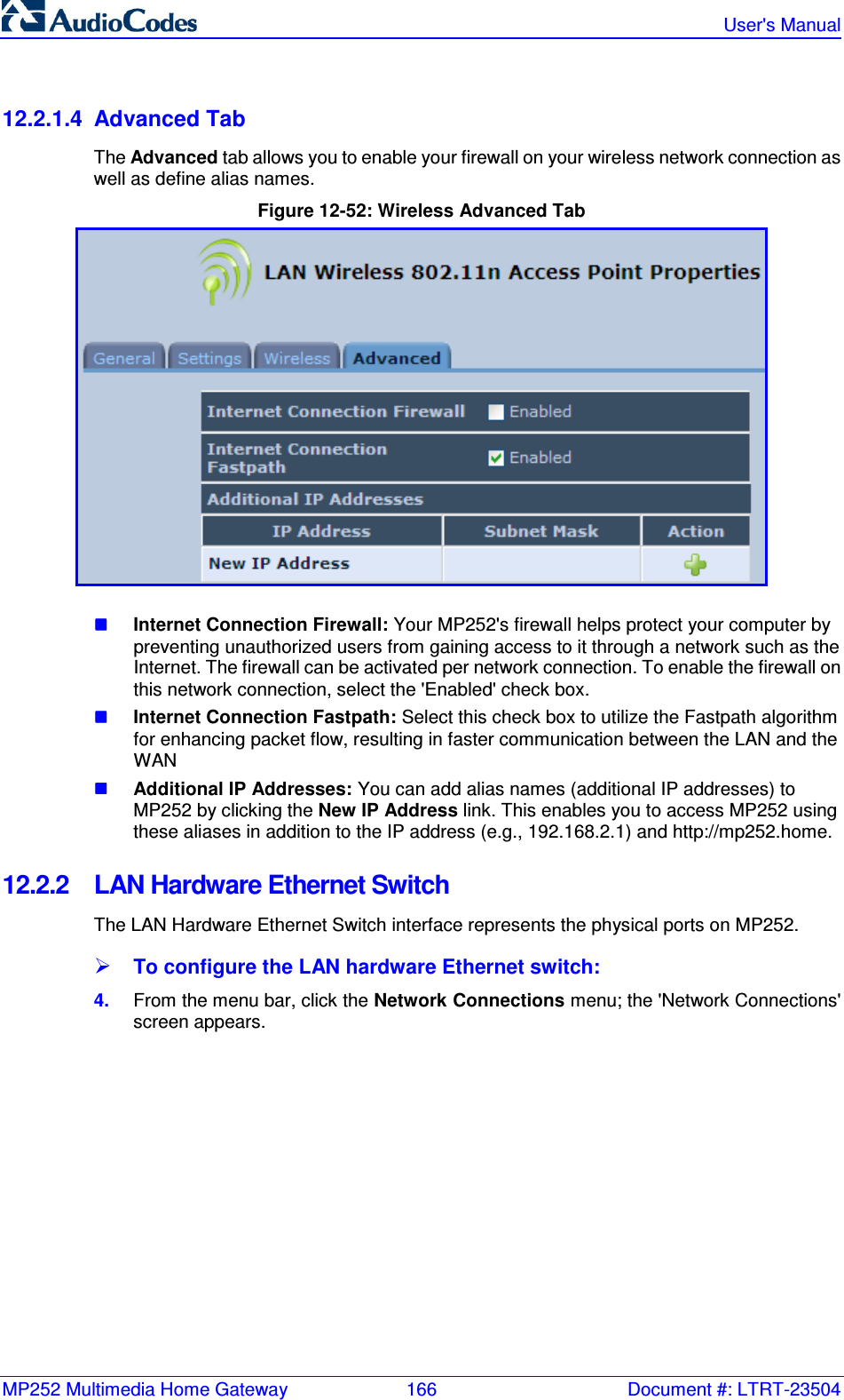
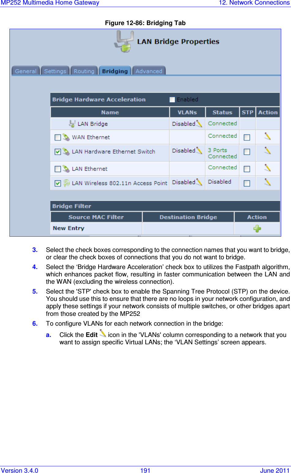
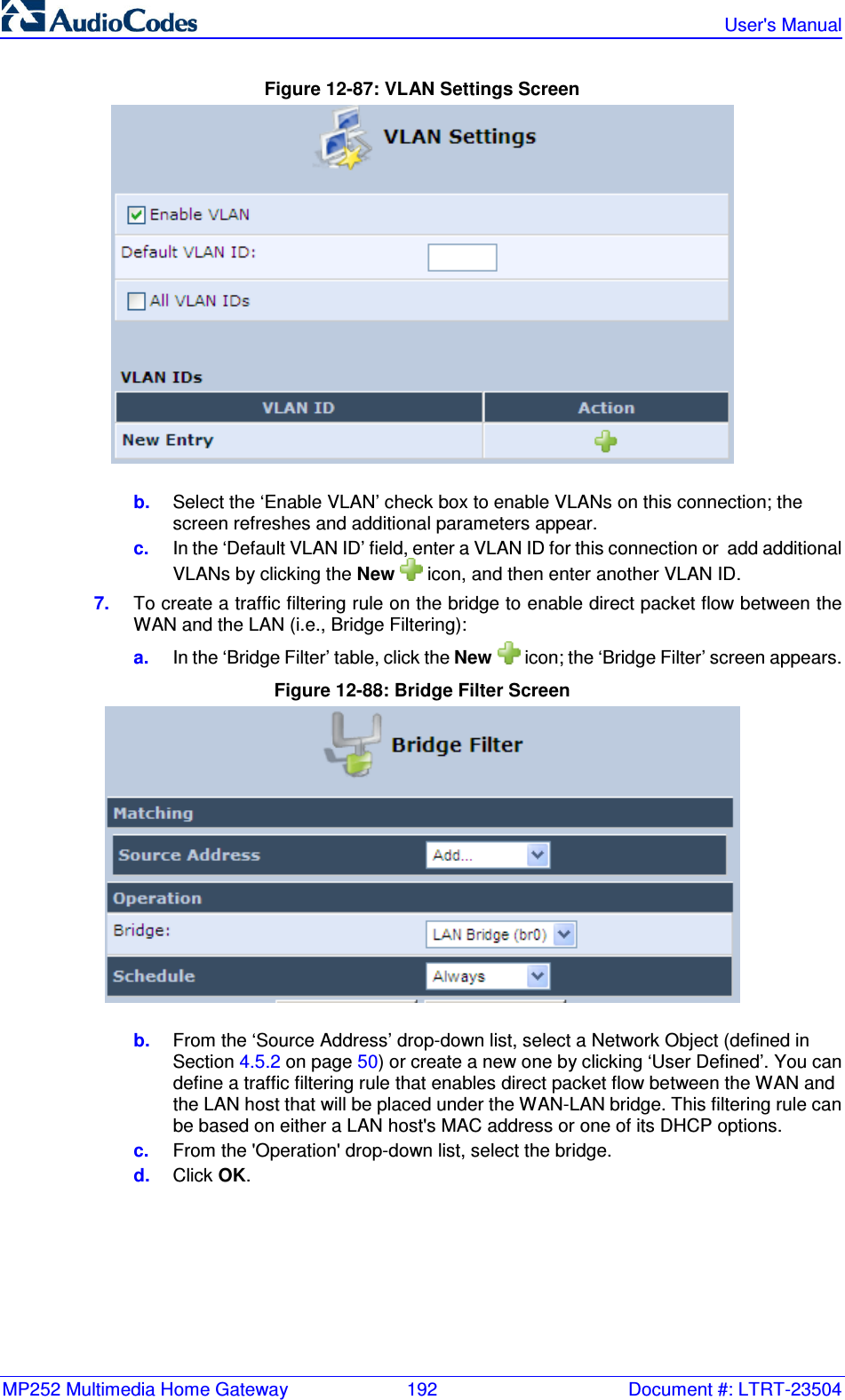
>
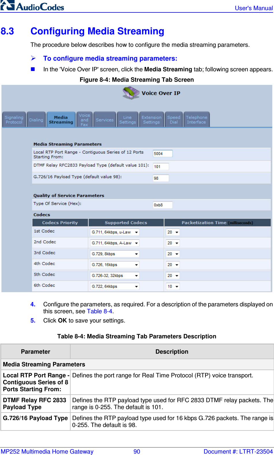
VTech Telecommunications
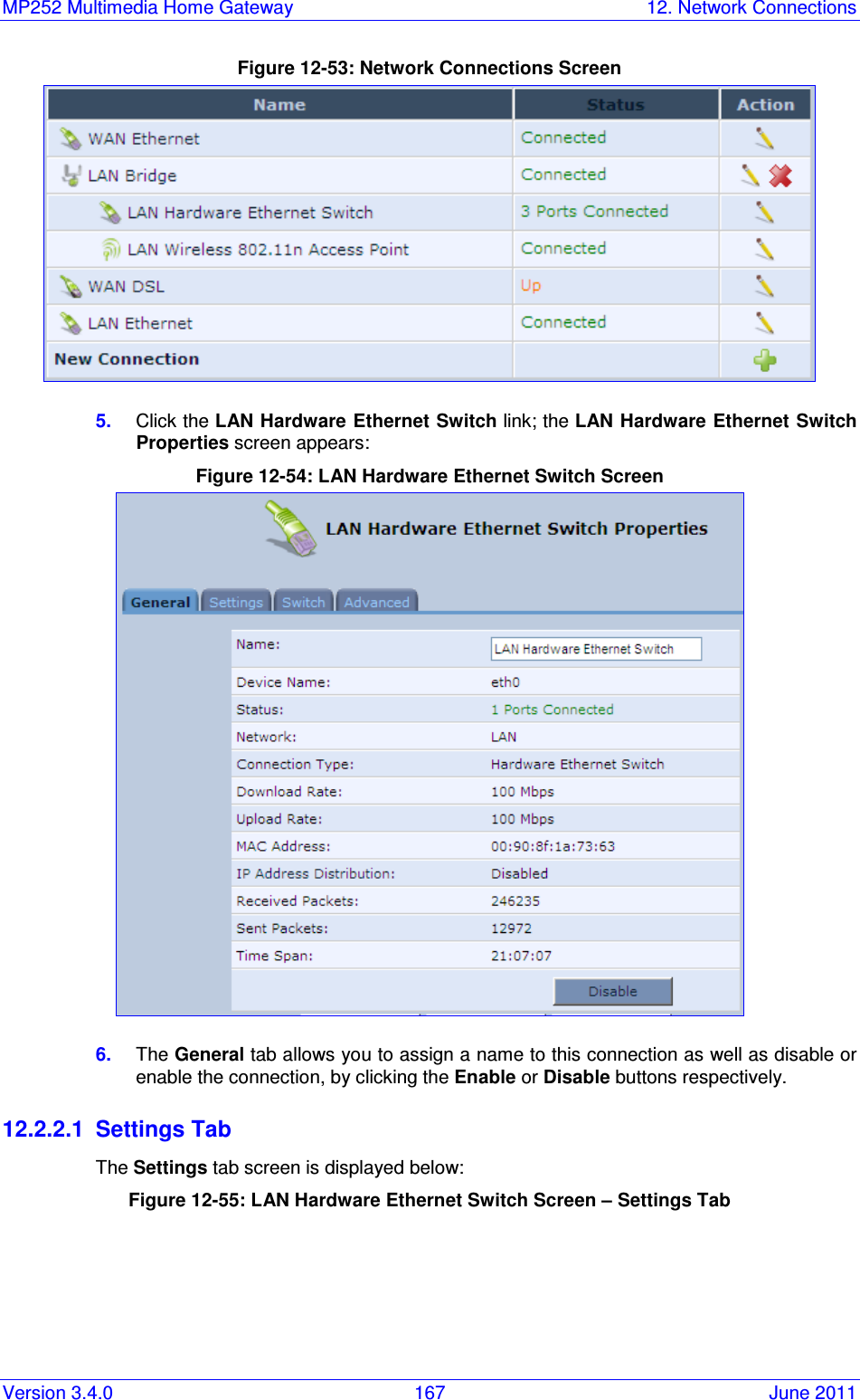
>
80-7597-01 User Manual
>
User Manual 1
Contents
1.
User Manual 1
2.
User Manual 2
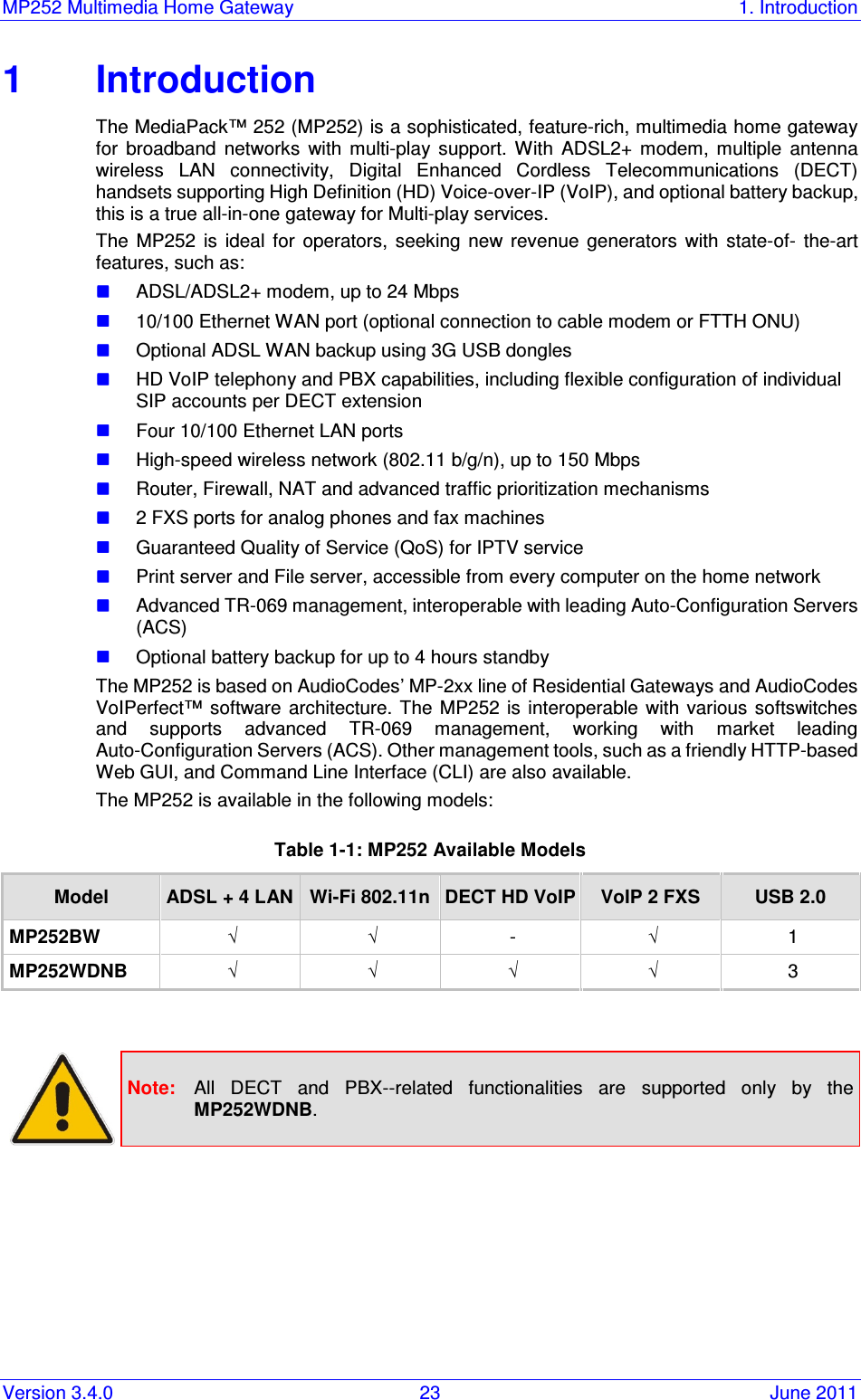
3.
User Manual 3
User Manual 1
Navigation menu
Upload a User Manual
Namespaces
Wiki Guide
HTML
PDF
Info
Views
User Manual
Discussion / Help
Navigation

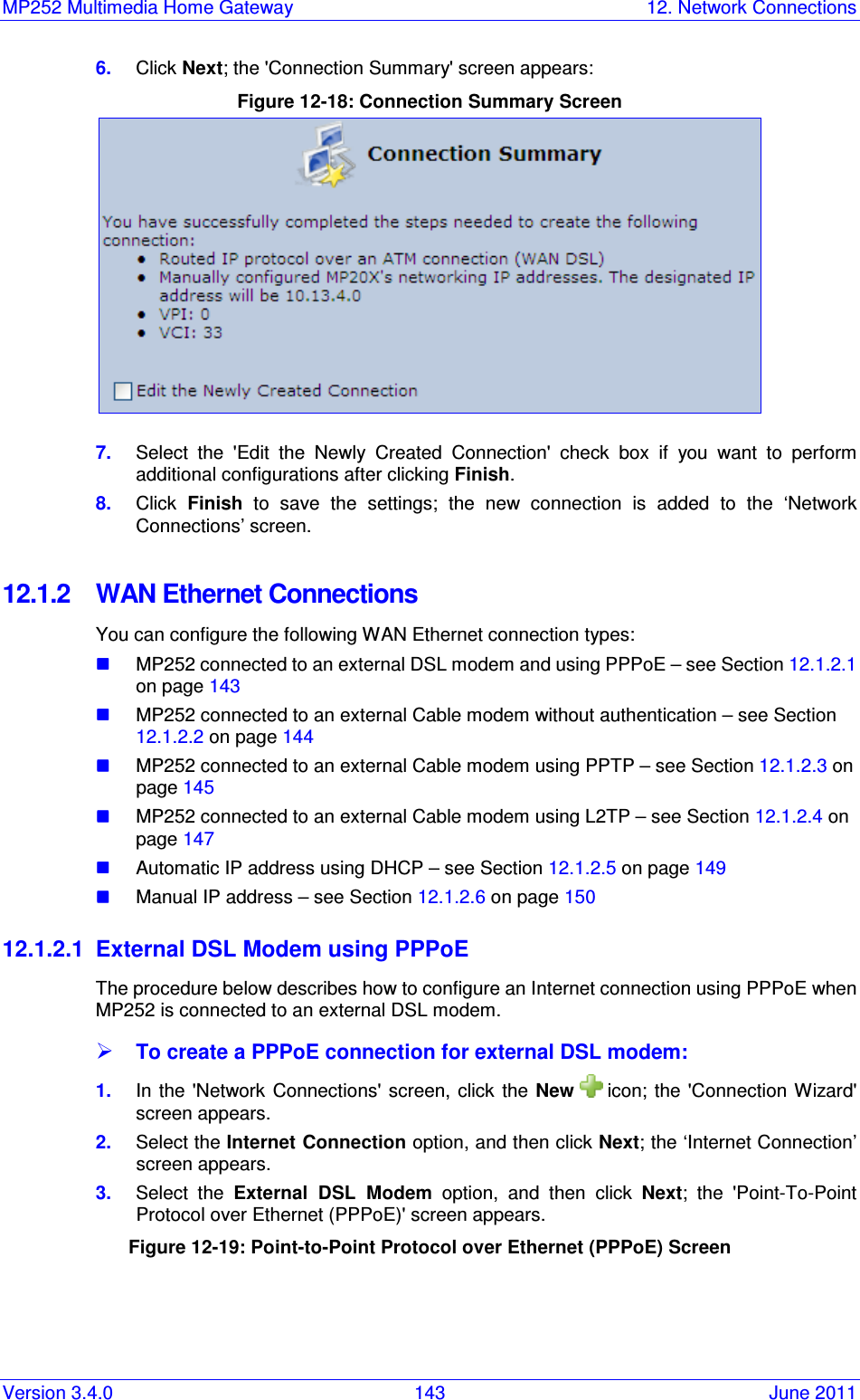
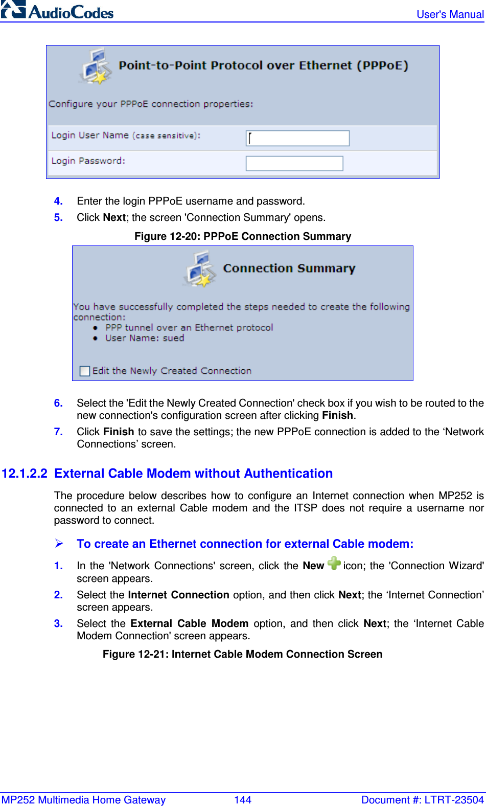
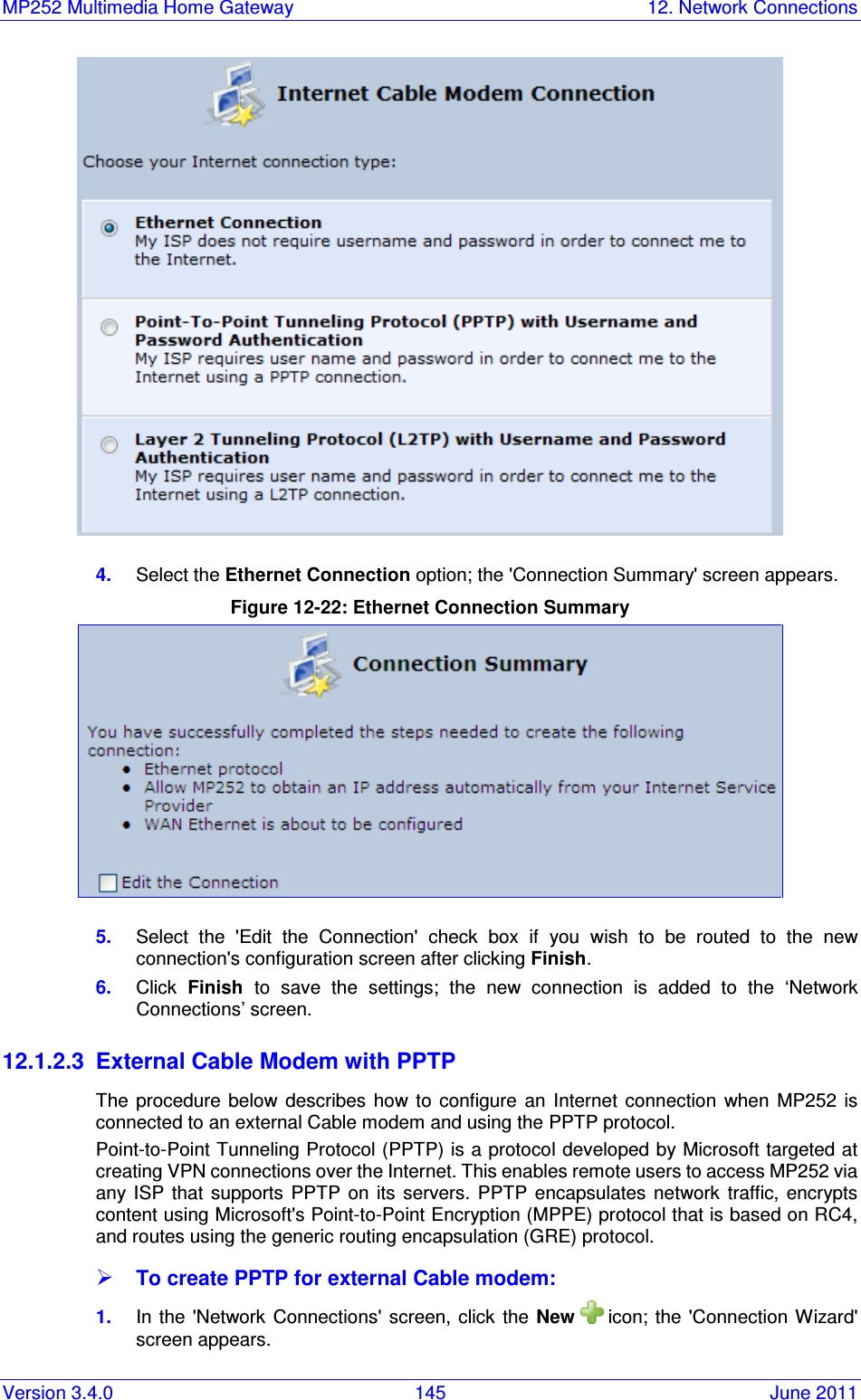
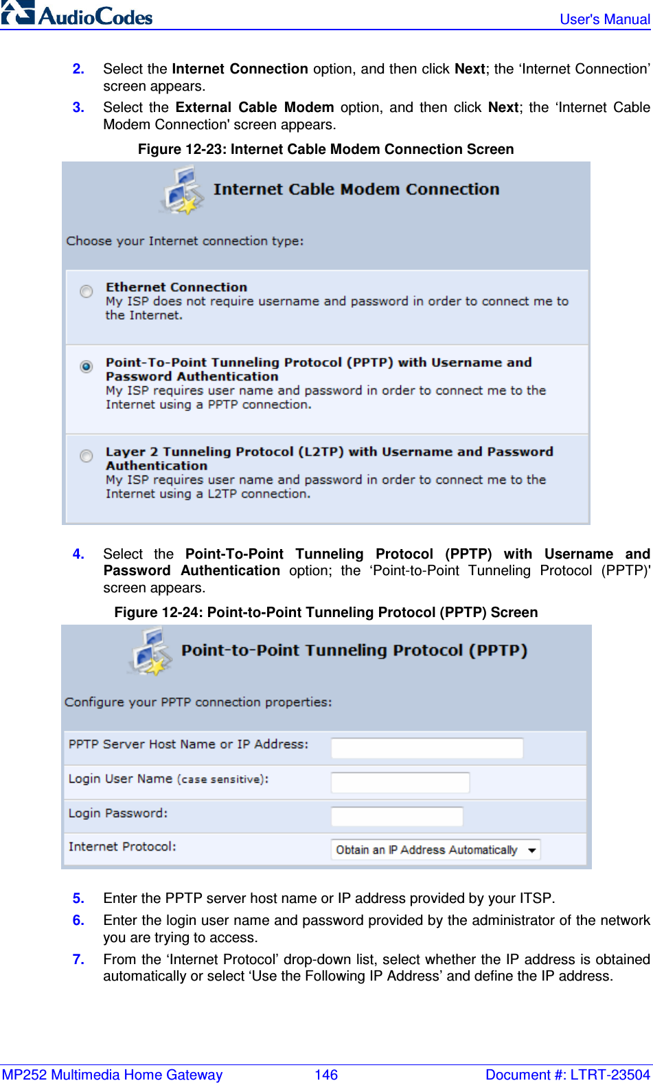
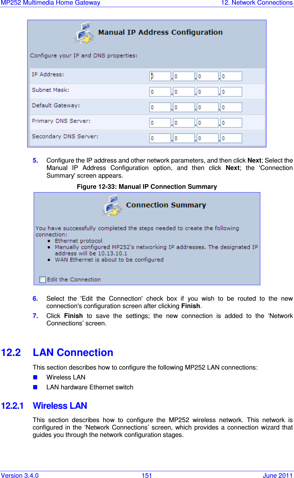
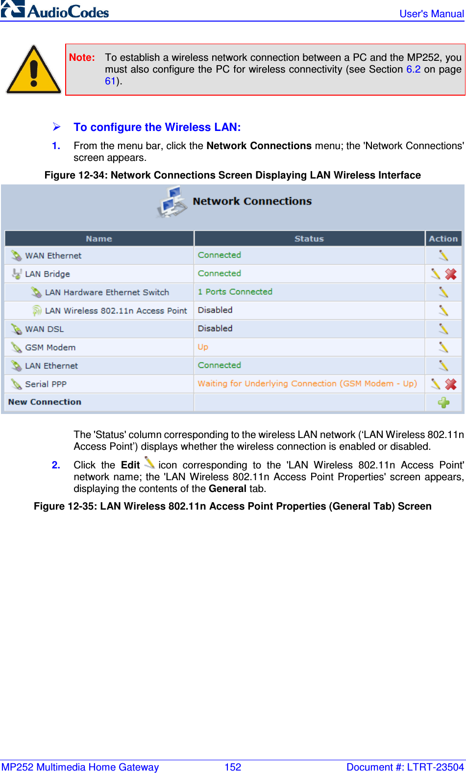
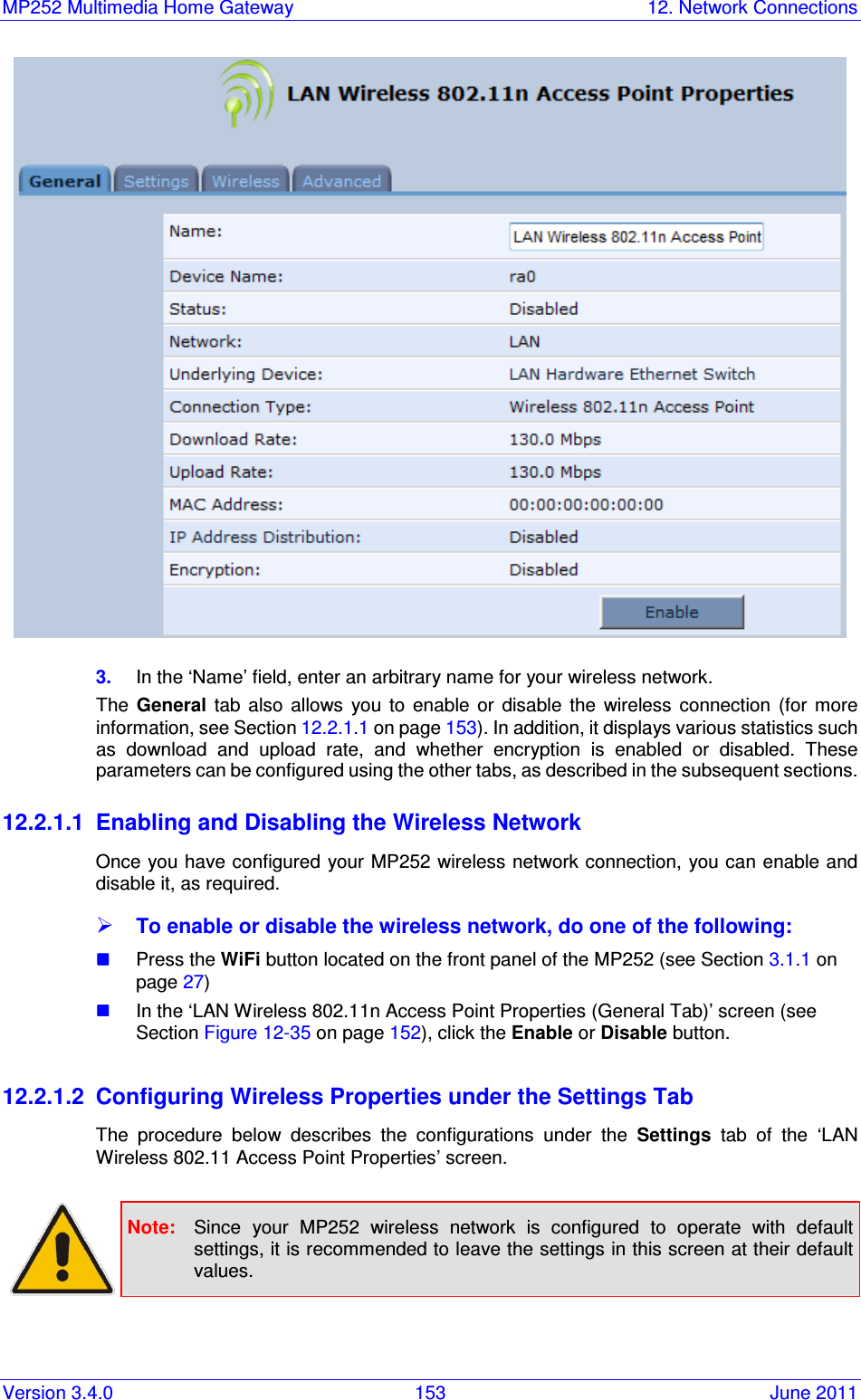
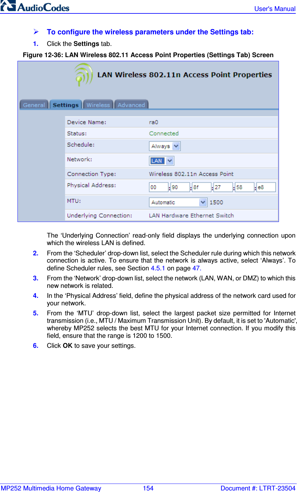
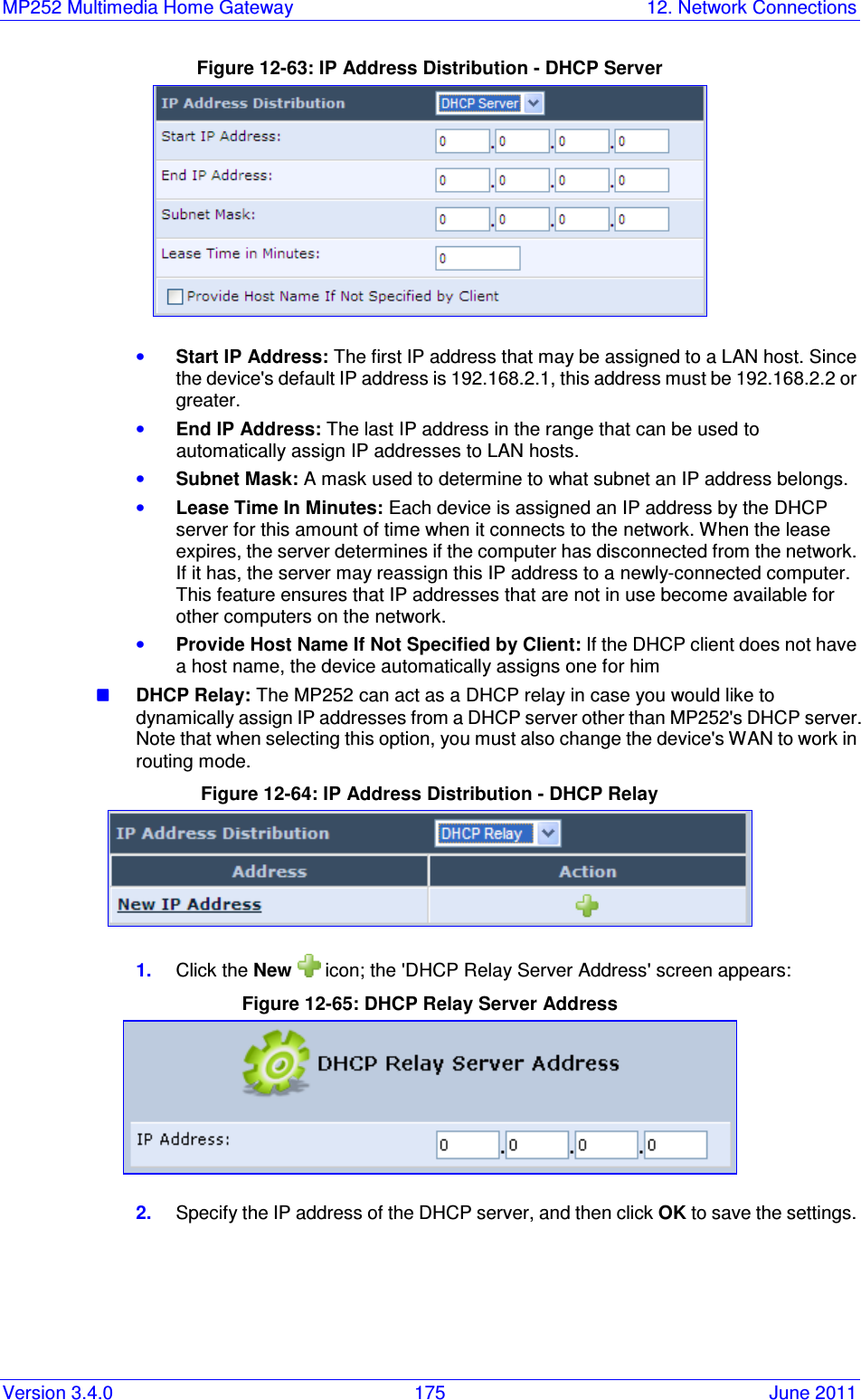
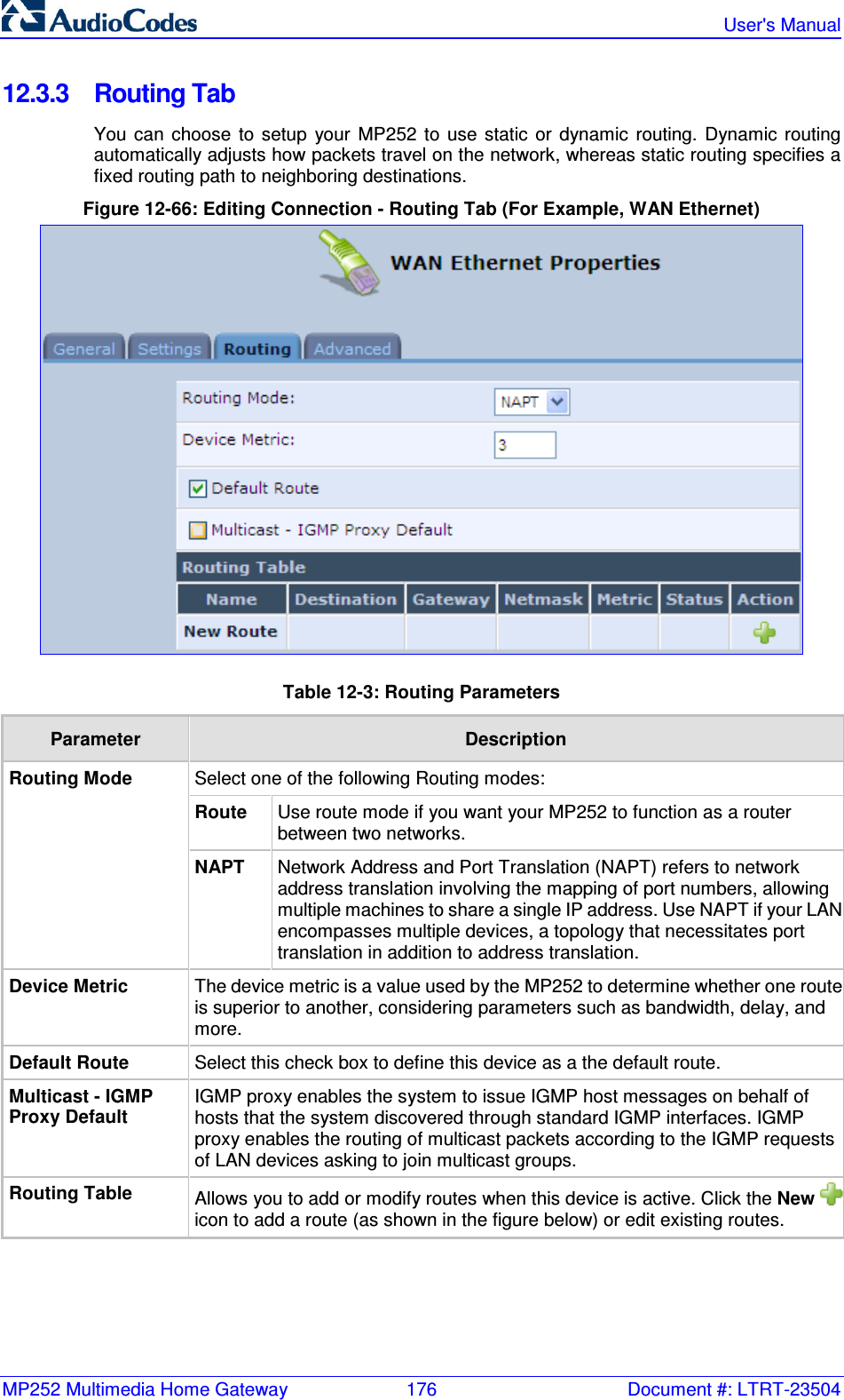
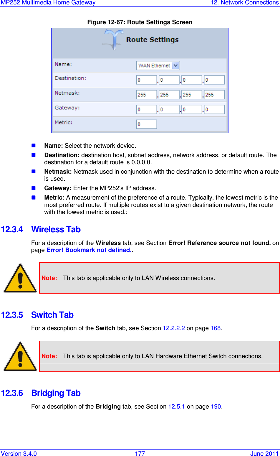
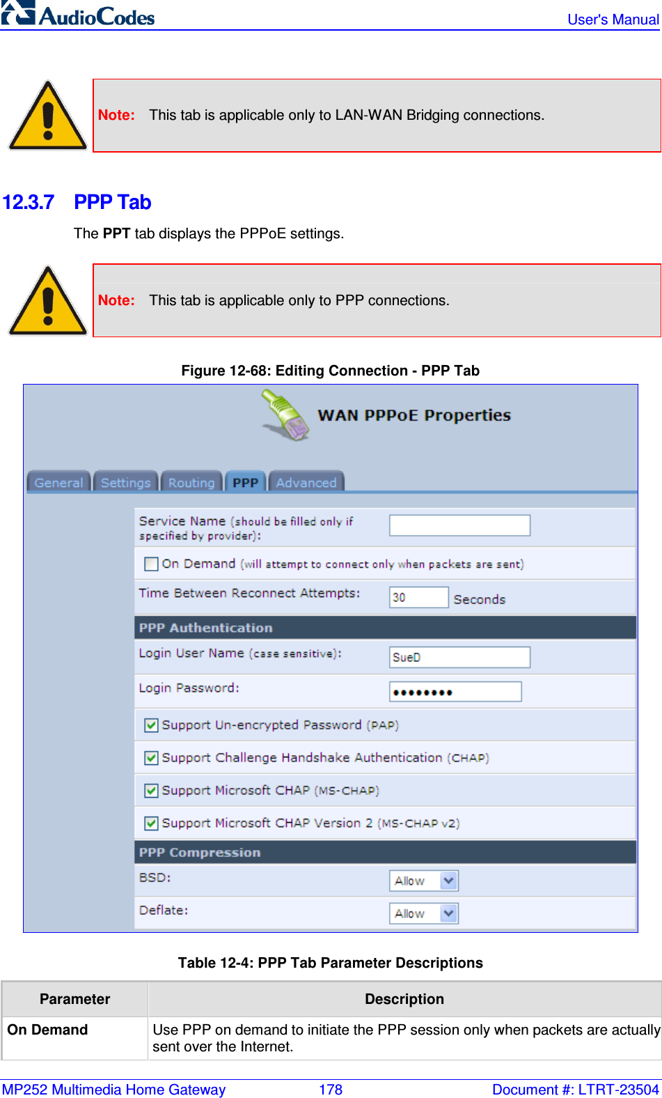
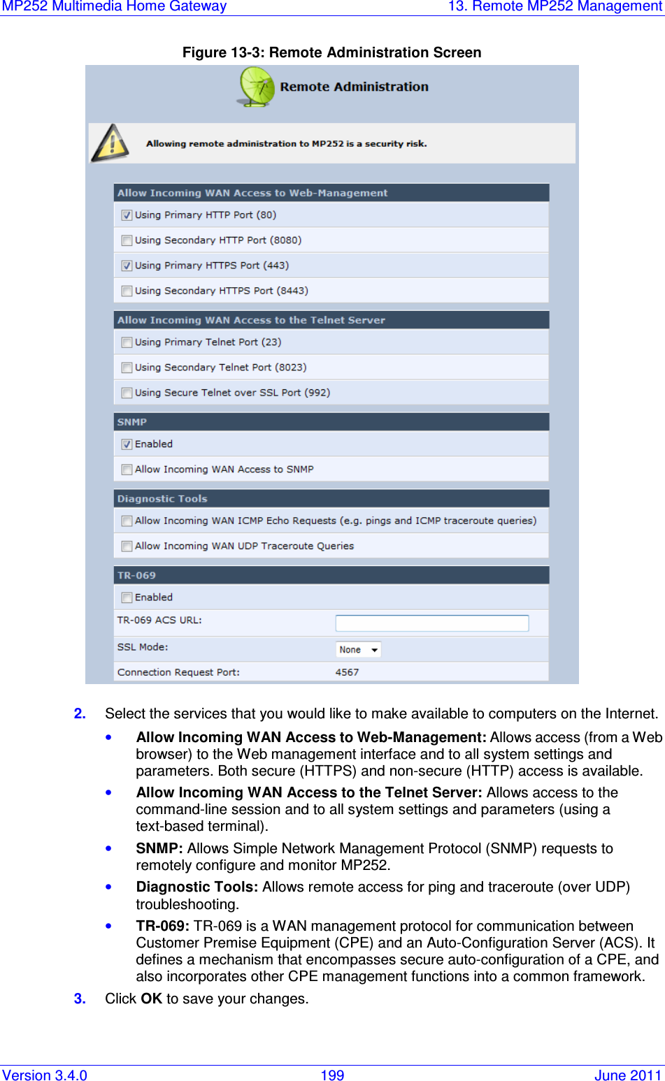
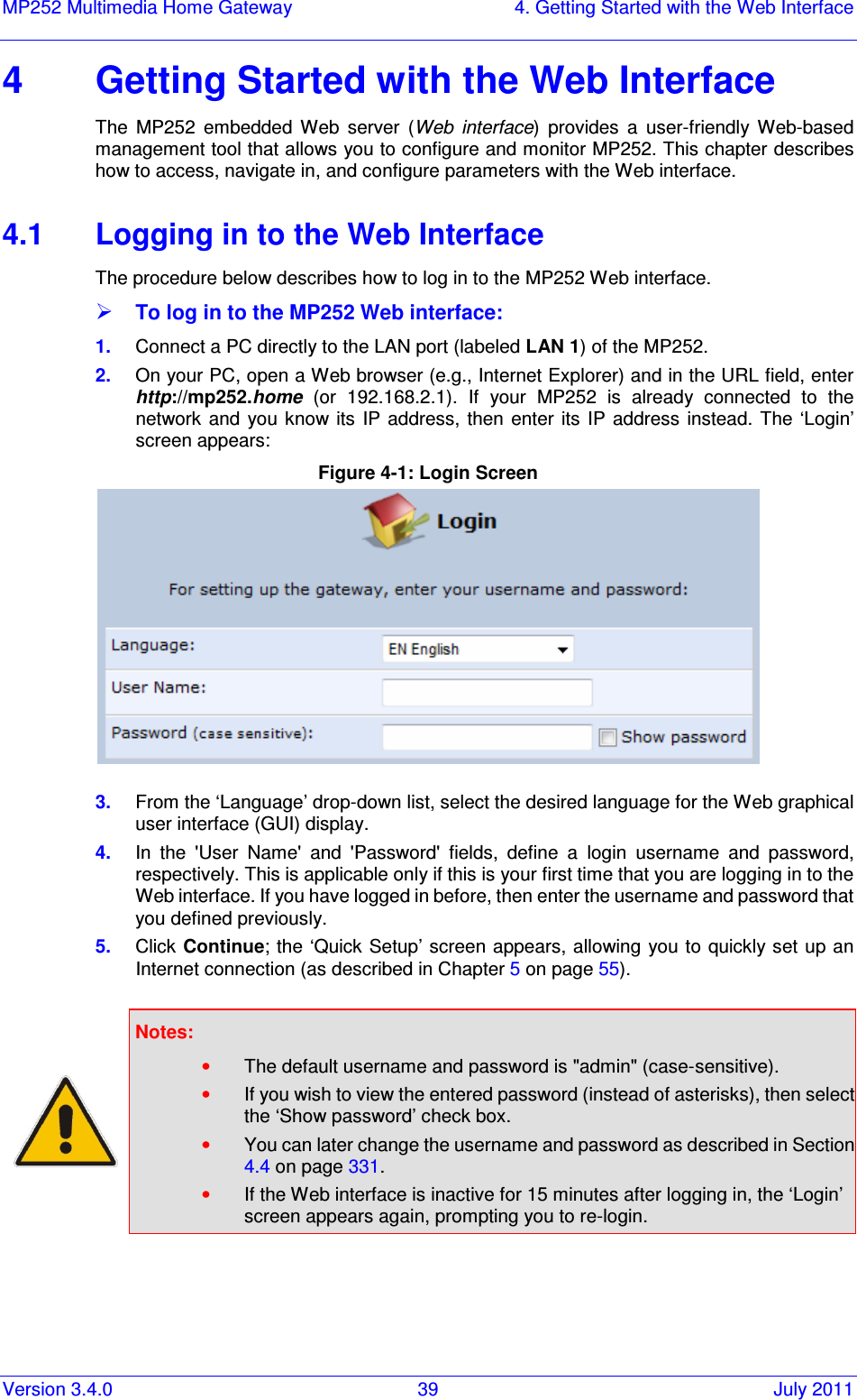
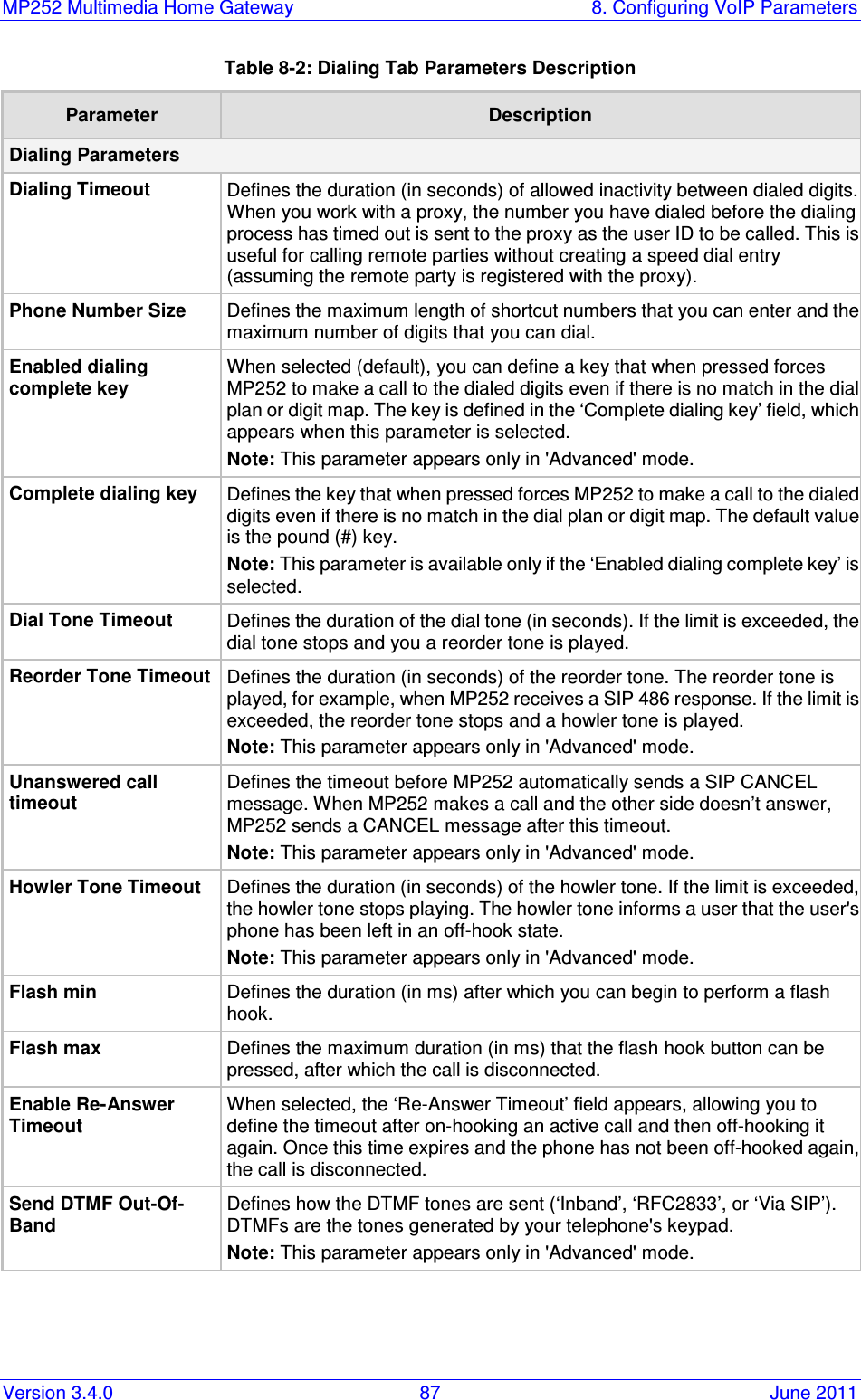
![MP252 Multimedia Home Gateway 1. Introduction Version 3.4.0 21 June 2011 For Customers in Canada This Class [B] digital apparatus complies with Canadian ICES-003. Cet appareil numérique de la classe [B] est conforme à la norme NMB-003 du Canada. Operation is subject to the following two conditions: (1) this device may not cause interference, and (2) this device must accept any interference, including interference that may cause undesired operation of the device. This device and its antenna(s) must not be co-located or operating in conjunction with any other antenna or transmitter. The County Code Selection feature is disabled for products marketed in the US/Canada. IC Radiation Exposure Statement This equipment complies with IC RSS-102 radiation exposure limits set forth for an uncontrolled environment. This equipment should be installed and operated with minimum distance of 20 cm between the radiator and your body.](https://usermanual.wiki/VTech-Telecommunications/80-7597-01.User-Manual-1/User-Guide-1590997-Page-21.png)


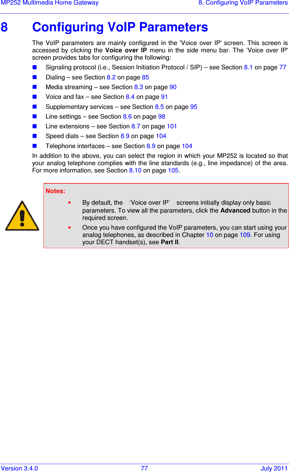
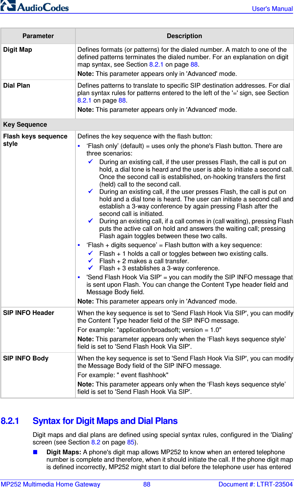
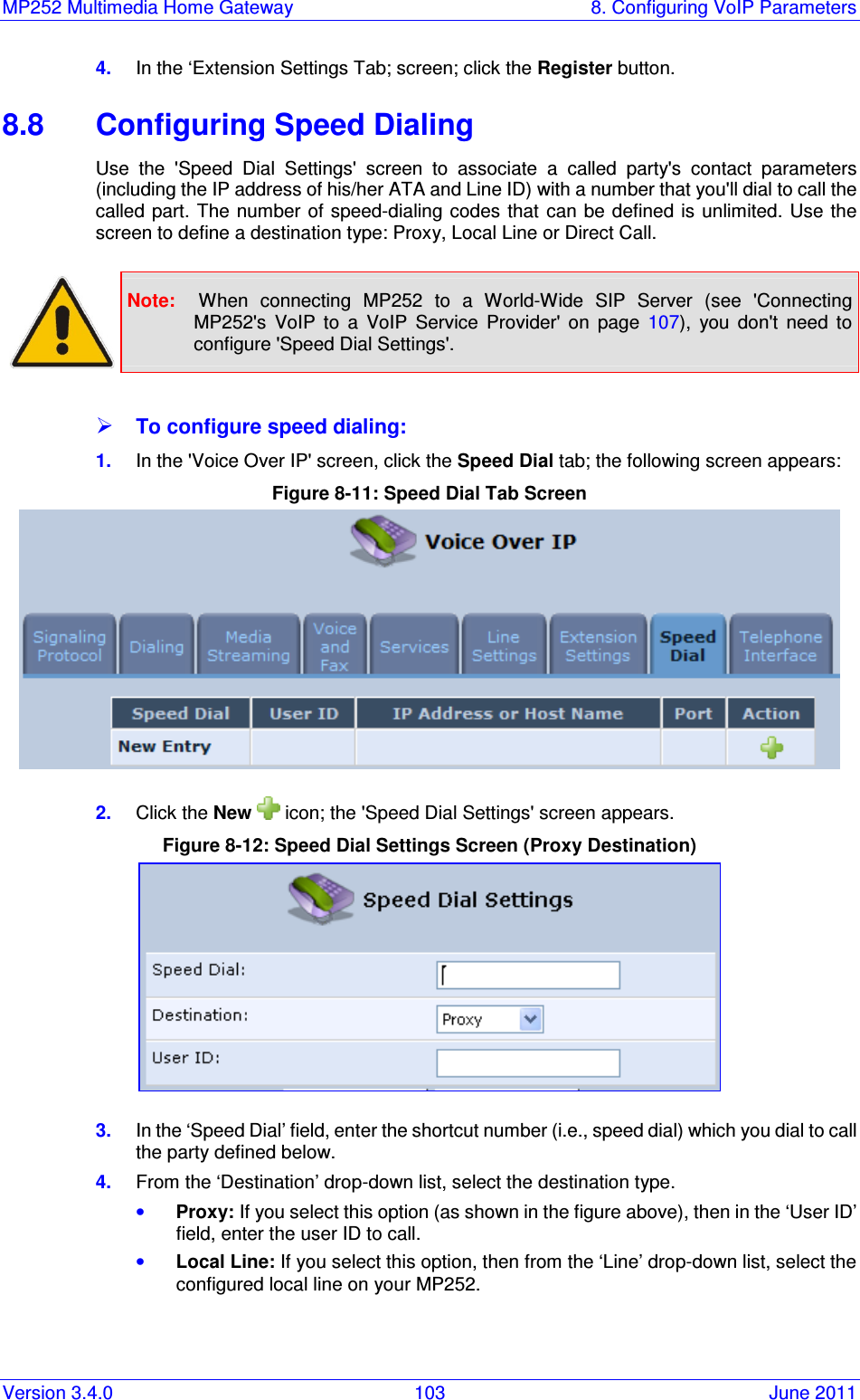
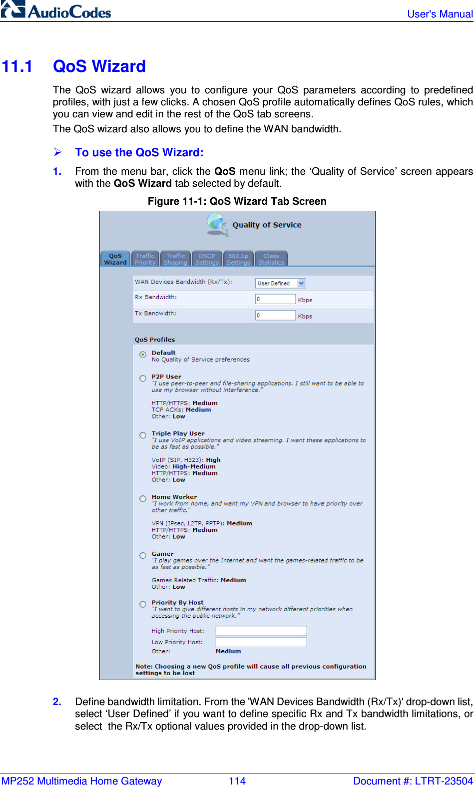
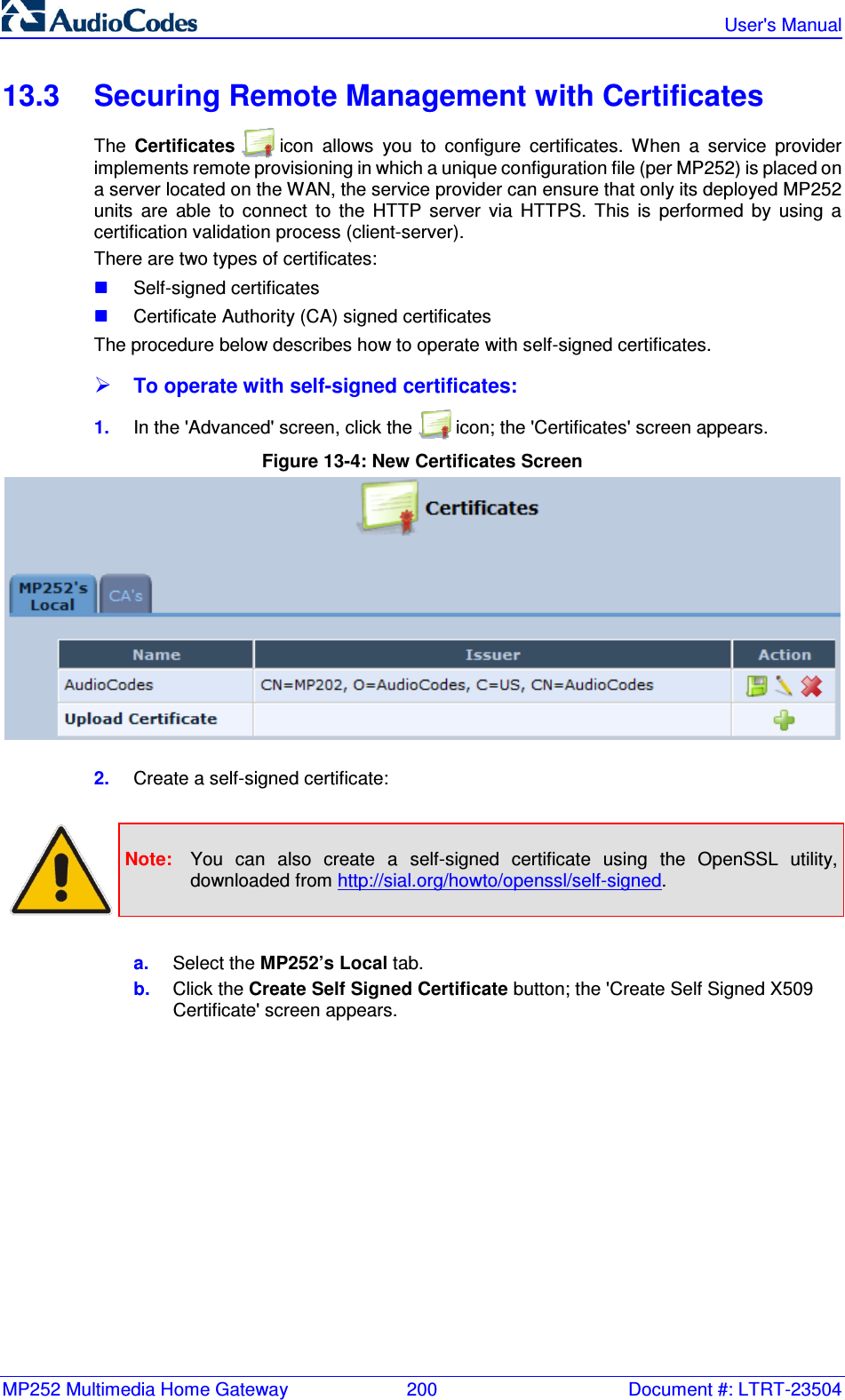
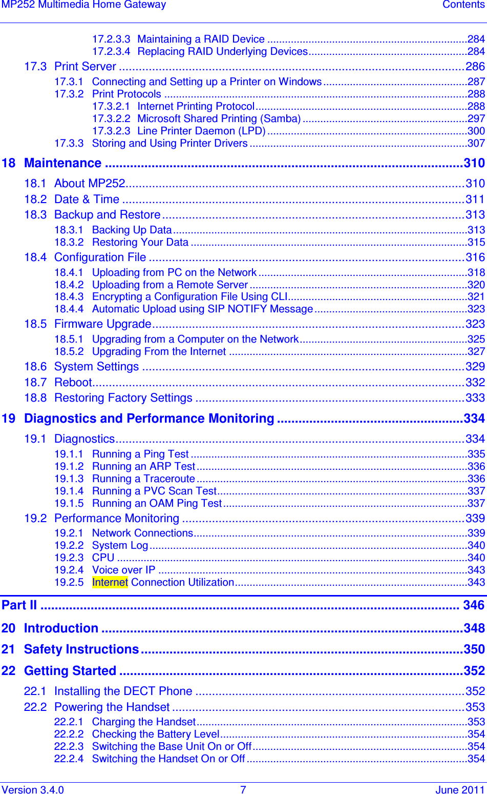
![MP252 Multimedia Home Gateway 8. Configuring VoIP Parameters Version 3.4.0 89 June 2011 all the required digits. A digit map is defined either by a (case insensitive) "string" or by a list of strings. Each string in the list is an alternative numbering scheme, specified either as a set of digits or as an expression over which MP252 attempts to find a shortest possible match. The syntax that can be used in each numbering scheme is described in the table below. Dial Plans: A dial plan translates specific patterns into specific SIP destination addresses. For example, dial plan rule "4xxx=Line_\\\@10.1.2.3" sends a dialed number consisting of the digit “4” followed by any three digits to IP address 10.1.2.3. The syntax of the pattern on the left of the '=' sign is described in the table below. Table 8-3: Dial Plan (for Left of '=' Sign) and Digit Map Syntax Type Syntax Digit A digit from "0" to "9". DTMF A digit, or one of the symbols "A", "B", "C", "D", "#", or "*". Extensions may be defined. Wildcard The symbol "x" which denotes any digit ("0" to "9"). Range One or more DTMF symbols enclosed between square brackets ("[" and "]"). Sub-range Two digits separated by a hyphen ("-") which matches any digit between and including the two. The subrange can only be used inside a range construct, i.e., between "[" and "]". Position A period (".") which matches an arbitrary number, including zero, of occurrences of the preceding construct. For example: [2-9]11|0|100|101|011xxx.|9011xxx.|1[2-9]xxxxxxxxx|91[2-9]xxxxxxxxx|9[2-9]xxxxxx|*xx|[8]xxxx|[2-7]xxx [2-9]11: 911 rule: 211, 311, 411, 511, 611, 711, 811, 911 are dialled immediately 0: Local operator rule 100: Auto-attendant default extension 101: Voicemail default extension 011xxx.: International rule without prefix 9011xxx.: International rule with prefix 1[2-9]xxxxxxxxx: LD rule without prefix 91[2-9]xxxxxxxxx: LD rule with prefix 9[2-9]xxxxxx: Local call with prefix *xx: 2-digit star codes [1-7]xx: A regular 3-digit extension that does not start with 9 or 8 is dialed immediately [2-7]xx: A regular 3-digit extension that does not start with 9, 8, or 1 is dialed immediately [2-7]xxx: A regular 4-digit extension that does not start with 9, 8, or 1 is dialed immediately [8]xxx: A 3-digit extension prefixed with an 8 (routes calls directly to voicemail of extension xxx) [8]xxxx: A-4 digit extension prefixed with an 8 (routes calls directly to voicemail of extension xxxx)](https://usermanual.wiki/VTech-Telecommunications/80-7597-01.User-Manual-1/User-Guide-1590997-Page-89.png)