VTech Telecommunications 80-7597-01 WiFi Gateway User Manual 1
VTech Telecommunications Ltd WiFi Gateway 1
Contents
- 1. User Manual 1
- 2. User Manual 2
- 3. User Manual 3
User Manual 1
AudioCodes CPE & Access Gateway Products
MP252 Multimedia Home Gateway
User's Manual
MP252BW and MP252WDNB
MediaPack™ 252 Multimedia Home Gateway Series
Version 3.4.0
Document #: LTRT-23504

Version 3.4.0 3 June 2011
MP252 Multimedia Home Gateway Contents
Contents
1
Introduction .......................................................................................................23
2
Package Contents and Prerequisites ..............................................................25
3
Hardware Description .......................................................................................27
3.1 Physical Description .............................................................................................27
3.1.1
Front Panel ..............................................................................................................27
3.1.1.1
Front-Panel Buttons Description ..............................................................28
3.1.1.2
Front-Panel LEDs Description..................................................................29
3.1.2
Rear Panel ...............................................................................................................30
3.1.2.1
Rear-Panel Port Description.....................................................................31
3.1.2.2
Rear-Panel LEDs Description ..................................................................32
3.2 Cabling .................................................................................................................33
3.3 Mounting ..............................................................................................................34
Part I ........................................................................................................................ 37
4
Getting Started with the Web Interface ...........................................................39
4.1 Logging in to the Web Interface............................................................................39
4.2 Menu Bar Description ...........................................................................................40
4.3 Managing Tables..................................................................................................43
4.4 Configuring Users.................................................................................................44
4.5 Defining Associated Elements ..............................................................................47
4.5.1
Defining Scheduler Rules ........................................................................................47
4.5.2
Defining Network Objects ........................................................................................50
4.5.3
Defining Protocols....................................................................................................51
4.6 Logging out the Web Interface..............................................................................53
5
Viewing a Graphical Display of the MP252 Network ......................................55
6
Configuring Computers for Connecting to the MP252 Network....................59
6.1 Wired Computers .................................................................................................59
6.1.1
Configuring Computers Running on Windows XP...................................................59
6.1.2
Configuring Computers Running on Linux...............................................................60
6.2 Connecting PC to MP252 Wireless Networks .......................................................61
7
Connecting MP252 to the Internet ...................................................................63
7.1 Quickly Setting up an Internet Connection in the Web Interface ...........................63
7.1.1
WAN Ethernet..........................................................................................................64
7.1.1.1
Manual IP Address Ethernet Connection .................................................65
7.1.1.2
Automatic IP Address Ethernet Connection.............................................65
7.1.1.3
PPPoE ......................................................................................................66
7.1.1.4
PPTP ........................................................................................................66
7.1.1.5
L2TP .........................................................................................................67
7.1.2
WAN DSL ................................................................................................................68
7.1.2.1
PPPoE ......................................................................................................68
7.1.2.2
PPPoA ......................................................................................................69
7.1.2.3
Routed ETHoA .........................................................................................69
7.1.2.4
Bridged ETHoA ........................................................................................70
7.1.2.5
CLIP..........................................................................................................70
7.2 Using the Automatic Dialer for Internet Connection ..............................................72
7.2.1
Recommended Configuration..................................................................................72
7.2.2
Setting up and Starting the Automatic Dialer...........................................................74

MP252 Multimedia Home Gateway 4 Document #: LTRT-23504
User's Manual
7.2.3
Quitting Automatic Dialer for Manual Configuration ................................................75
8
Configuring VoIP Parameters ..........................................................................77
8.1 Configuring the SIP Signaling Protocol.................................................................78
8.1.1
Configuring Proxy Redundancy...............................................................................84
8.2 Configuring Dialing Parameters............................................................................86
8.2.1
Syntax for Digit Maps and Dial Plans ......................................................................88
8.3 Configuring Media Streaming ...............................................................................90
8.3.1
Configuring Codecs .................................................................................................91
8.3.1.1
Supported Codecs....................................................................................91
8.3.1.2
Packetization Time...................................................................................91
8.4 Configuring Voice and Fax ...................................................................................91
8.5 Configuring Supplementary Services....................................................................95
8.6 Configuring Line Settings .....................................................................................99
8.7 Configuring Line Extensions...............................................................................102
8.8 Configuring Speed Dialing..................................................................................103
8.9 Enabling Polarity Reversal..................................................................................104
8.10 Selecting Regional Settings for Analog Lines .....................................................105
9
Connecting MP252 to an ITSP........................................................................107
9.1 Opening a SIP Account ......................................................................................107
9.2 Configuring VoIP Parameters.............................................................................107
10
Making VoIP Calls with your Analog Telephones ........................................109
10.1 Making a Call......................................................................................................109
10.2 Answering a Waiting Call....................................................................................109
10.3 Placing a Call on Hold ........................................................................................110
10.4 Transferring a Call..............................................................................................110
10.5 Establishing a 3-Way Conference Call................................................................111
10.6 Forwarding Calls to another Phone ....................................................................112
11
Quality of Service............................................................................................113
11.1 QoS Wizard........................................................................................................114
11.2 Traffic Shaping ...................................................................................................115
11.2.1
Device Traffic Shaping...........................................................................................115
11.2.2
Shaping Classes....................................................................................................117
11.2.2.1
Class Rules ............................................................................................118
11.3 Traffic Priority .....................................................................................................120
11.4 DSCP Mapping...................................................................................................123
11.5 802.1p Mapping..................................................................................................126
11.6 Class Statistics ...................................................................................................127
11.7 Configuring Basic VoIP QoS...............................................................................128
12
Network Connections .....................................................................................131
12.1 Configuring a WAN Connection..........................................................................131
12.1.1
WAN DSL Connections .........................................................................................133
12.1.1.1
Determine Protocol Type Automatically (PVC Scan).............................133
12.1.1.2
PPPoE ....................................................................................................134
12.1.1.3
PPPoA ....................................................................................................136
12.1.1.4
Routed ETHoA or Bridged ETHoA.........................................................138
12.1.1.5
CLIP........................................................................................................140

Version 3.4.0 5 June 2011
MP252 Multimedia Home Gateway Contents
12.1.1.6
IPoA........................................................................................................142
12.1.2
WAN Ethernet Connections...................................................................................143
12.1.2.1
External DSL Modem using PPPoE.......................................................143
12.1.2.2
External Cable Modem without Authentication ......................................144
12.1.2.3
External Cable Modem with PPTP.........................................................145
12.1.2.4
External Cable Modem with L2TP..........................................................147
12.1.2.5
DHCP .....................................................................................................149
12.1.2.6
Manual IP Address .................................................................................150
12.2 LAN Connection .................................................................................................151
12.2.1
Wireless LAN .........................................................................................................151
12.2.1.1
Enabling and Disabling the Wireless Network .......................................153
12.2.1.2
Configuring Wireless Properties under the Settings Tab .......................153
12.2.1.3
Configuring Wireless Properties under the Wireless Tab ......................155
12.2.1.4
Advanced Tab ........................................................................................166
12.2.2
LAN Hardware Ethernet Switch .............................................................................166
12.2.2.1
Settings Tab ...........................................................................................167
12.2.2.2
Switch Tab..............................................................................................168
12.2.2.3
Advanced Tab ........................................................................................170
12.3 Editing Network Connections and Advanced Configuration ................................170
12.3.1
General Tab...........................................................................................................171
12.3.2
Settings Tab...........................................................................................................171
12.3.2.1
Internet Protocol Settings .......................................................................173
12.3.3
Routing Tab ...........................................................................................................176
12.3.4
Wireless Tab..........................................................................................................177
12.3.5
Switch Tab .............................................................................................................177
12.3.6
Bridging Tab ..........................................................................................................177
12.3.7
PPP Tab ................................................................................................................178
12.3.8
PPTP tab ...............................................................................................................179
12.3.9
Advanced Tab........................................................................................................180
12.4 VLAN Settings ....................................................................................................181
12.4.1
Settings Tab...........................................................................................................183
12.4.1.1
IP Address Distribution...........................................................................184
12.4.2
Routing Tab ...........................................................................................................186
12.4.3
Advanced Tab........................................................................................................187
12.5 LAN-WAN Bridge Settings..................................................................................188
12.5.1
Editing LAN-WAN Bridging ....................................................................................190
13
Remote MP252 Management..........................................................................193
13.1 Overview ............................................................................................................193
13.1.1
Remote Configuration............................................................................................193
13.1.2
Remote Management ............................................................................................194
13.1.2.1
Firmware Upgrade..................................................................................195
13.1.2.2
Status and Performance Monitoring.......................................................196
13.1.2.3
Alarms, Notifications and Logging..........................................................197
13.2 Enabling Remote Management ..........................................................................197
13.3 Securing Remote Management with Certificates ................................................200
13.4 Remote Configuration and Management Interfaces............................................205
13.4.1
Embedded Web Server .........................................................................................205
13.4.2
TR-069 and TR-104 CPE WAN Management Protocol ........................................206
13.4.2.1
Configuring MP252 via TR-069 and TR-104..........................................207
13.4.2.2
Monitoring MP252 Status via TR-069 and TR-104 ................................215
13.4.2.3
Security Concerns and Measures ..........................................................219
13.4.3
SNMP.....................................................................................................................220
13.4.3.1
Enabling SNMP in the Web Interface.....................................................220
13.4.3.2
Configuring MP252 via SNMP ...............................................................221
13.4.3.3
Status Monitoring of System and Network Interfaces via SNMP ...........222

MP252 Multimedia Home Gateway 6 Document #: LTRT-23504
User's Manual
13.4.3.4
Security Concerns and Measures ..........................................................222
13.4.4
Syslog ....................................................................................................................223
13.4.5
Automatic File Download .......................................................................................223
13.4.5.1
Firmware File Download.........................................................................223
13.4.5.2
Configuration File Download ..................................................................223
13.4.5.3
Security Concerns and Measures ..........................................................224
13.4.6
Telnet CLI ..............................................................................................................224
14
Security............................................................................................................225
14.1 General Security Level Settings..........................................................................226
14.2 Access Control ...................................................................................................228
14.3 Port Forwarding..................................................................................................229
14.4 DMZ Host ...........................................................................................................234
14.5 Port Triggering....................................................................................................235
14.6 Website Restrictions...........................................................................................237
14.7 NAT....................................................................................................................240
14.8 Connections .......................................................................................................244
14.9 Advanced Filtering..............................................................................................245
14.10 Security Log .......................................................................................................248
15
Advanced Networking Features.....................................................................251
15.1 IP Address Distribution .......................................................................................251
15.1.1
DHCP Server Parameters .....................................................................................253
15.1.2
DHCP Relay Parameters.......................................................................................254
15.1.3
Viewing DHCP Clients ...........................................................................................255
15.1.4
Defining Static DHCP Clients ................................................................................255
15.2 DNS Server ........................................................................................................257
15.3 Dynamic DNS.....................................................................................................258
15.4 Routing...............................................................................................................261
15.4.1
Managing Routing Table Rules .............................................................................261
15.4.2
Routing Protocols ..................................................................................................262
15.5 PPPoE Relay......................................................................................................262
16
Home Media .....................................................................................................265
16.1 Universal Plug and Play .....................................................................................265
16.1.1
Enabling UPnP on MP252 .....................................................................................265
16.1.2
Adding UPnP-enabled PC to Home Network ........................................................266
16.1.3
Monitoring Connection between MP252 and Internet ...........................................266
16.1.4
Making Local Services available to PCs on Internet .............................................267
17
Add-On Servers and Disk Management ........................................................270
17.1 External File Server............................................................................................270
17.1.1
Automatic File Sharing...........................................................................................271
17.2 Disk Management ..............................................................................................272
17.2.1
Disk Partitions ........................................................................................................274
17.2.1.1
Connecting a Mass Storage Device.......................................................274
17.2.1.2
Formatting a Partition .............................................................................278
17.2.1.3
Checking a Partition ...............................................................................279
17.2.1.4
Deleting a Partition .................................................................................279
17.2.2
System Storage Area.............................................................................................280
17.2.3
RAID Management ................................................................................................282
17.2.3.1
Creating a RAID Device .........................................................................282
17.2.3.2
Using a RAID Device..............................................................................284

Version 3.4.0 7 June 2011
MP252 Multimedia Home Gateway Contents
17.2.3.3
Maintaining a RAID Device ....................................................................284
17.2.3.4
Replacing RAID Underlying Devices......................................................284
17.3 Print Server ........................................................................................................286
17.3.1
Connecting and Setting up a Printer on Windows.................................................287
17.3.2
Print Protocols .......................................................................................................288
17.3.2.1
Internet Printing Protocol........................................................................288
17.3.2.2
Microsoft Shared Printing (Samba) ........................................................297
17.3.2.3
Line Printer Daemon (LPD) ....................................................................300
17.3.3
Storing and Using Printer Drivers ..........................................................................307
18
Maintenance ....................................................................................................310
18.1 About MP252......................................................................................................310
18.2 Date & Time .......................................................................................................311
18.3 Backup and Restore...........................................................................................313
18.3.1
Backing Up Data....................................................................................................313
18.3.2
Restoring Your Data ..............................................................................................315
18.4 Configuration File ...............................................................................................316
18.4.1
Uploading from PC on the Network .......................................................................318
18.4.2
Uploading from a Remote Server ..........................................................................320
18.4.3
Encrypting a Configuration File Using CLI.............................................................321
18.4.4
Automatic Upload using SIP NOTIFY Message....................................................323
18.5 Firmware Upgrade..............................................................................................323
18.5.1
Upgrading from a Computer on the Network.........................................................325
18.5.2
Upgrading From the Internet .................................................................................327
18.6 System Settings .................................................................................................329
18.7 Reboot................................................................................................................332
18.8 Restoring Factory Settings .................................................................................333
19
Diagnostics and Performance Monitoring ....................................................334
19.1 Diagnostics.........................................................................................................334
19.1.1
Running a Ping Test ..............................................................................................335
19.1.2
Running an ARP Test ............................................................................................336
19.1.3
Running a Traceroute ............................................................................................336
19.1.4
Running a PVC Scan Test.....................................................................................337
19.1.5
Running an OAM Ping Test...................................................................................337
19.2 Performance Monitoring .....................................................................................339
19.2.1
Network Connections.............................................................................................339
19.2.2
System Log ............................................................................................................340
19.2.3
CPU .......................................................................................................................340
19.2.4
Voice over IP .........................................................................................................343
19.2.5
Internet Connection Utilization...............................................................................343
Part II ..................................................................................................................... 346
20
Introduction .....................................................................................................348
21
Safety Instructions..........................................................................................350
22
Getting Started ................................................................................................352
22.1 Installing the DECT Phone .................................................................................352
22.2 Powering the Handset ........................................................................................353
22.2.1
Charging the Handset............................................................................................353
22.2.2
Checking the Battery Level....................................................................................354
22.2.3
Switching the Base Unit On or Off.........................................................................354
22.2.4
Switching the Handset On or Off ...........................................................................354

MP252 Multimedia Home Gateway 8 Document #: LTRT-23504
User's Manual
22.2.5
Replacing the Batteries..........................................................................................355
22.3 Getting to Know Your Phone ..............................................................................356
22.3.1
Overview of the Handset .......................................................................................356
22.3.2
Getting to Know your Handset LCD Screen..........................................................359
22.3.2.1
Menu Structure .......................................................................................360
22.3.2.2
Entering Text and Digits .........................................................................361
22.3.3
Viewing Base Unit Status with DECT LED ............................................................363
22.4 Upgrading MP252 and the Base Unit .................................................................363
22.5 Defining the MP252 Handset Line ......................................................................364
22.6 Registering the Handset to Base Unit.................................................................366
22.7 Checking the Handset Signal Strength ...............................................................367
23
General Phone Operation...............................................................................368
23.1 Making an External Call......................................................................................368
23.1.1
Pre-dialing..............................................................................................................368
23.1.2
Direct Dialing .........................................................................................................368
23.1.3
Calling from your Phonebook ................................................................................368
23.1.4
Calling from the Call List........................................................................................368
23.1.5
Establishing a Second Call ....................................................................................368
23.1.6
Redialing a Number ...............................................................................................369
23.2 Answering a Call ................................................................................................369
23.3 Answering or Rejecting a Second Call................................................................370
23.4 Ending a Call......................................................................................................370
23.5 Adjusting Earpiece and Speakerphone Volume during a Call .............................370
23.6 Muting a Call ......................................................................................................370
23.7 Turning Off the Ringer ........................................................................................371
23.8 Redial List ..........................................................................................................371
23.8.1
Saving a Redial Number to the Phonebook ..........................................................371
23.8.2
Deleting a Number from the Redial List.................................................................372
23.8.3
Deleting the Entire Redial List ...............................................................................372
23.9 Locking the Keypad............................................................................................372
23.10 Paging the Handset............................................................................................372
23.11 Call Handling for Multiple, Registered Handsets.................................................373
23.11.1
Calling (Intercom) Another Handset ......................................................................373
23.11.2
Transferring an External Call to Another Handset.................................................373
23.11.2.1
Announced Call Transfer........................................................................373
23.11.2.2
Unannounced Call Transfer ...................................................................373
23.11.3
Transferring an External Call to Another External Call..........................................374
23.11.4
Toggling between External and Internal Calls.......................................................374
23.11.5
Three-Way Conference Calls ................................................................................375
23.11.5.1
Making a Three-Way Conference Call with Another Handset and an
External Party ........................................................................................................375
23.11.5.2
Making a Three-Way Conference Call with your Handset and two External
Calls 376
24
Phonebook.......................................................................................................377
24.1 Adding a New Contact........................................................................................377
24.2 Editing a Contact ................................................................................................378
24.3 Viewing Contacts................................................................................................378
24.4 Deleting a Contact..............................................................................................379
24.5 Deleting All Contacts ..........................................................................................380
25
Call List ............................................................................................................381

Version 3.4.0 9 June 2011
MP252 Multimedia Home Gateway Contents
25.1 Viewing the Call List ...........................................................................................381
25.2 Saving a Call List Number to the Phonebook......................................................382
25.3 Dialing a Call List Number ..................................................................................382
25.4 Deleting a Call List Number................................................................................383
25.5 Deleting the Entire Call List ................................................................................384
26
Clock and Alarm..............................................................................................385
26.1 Date and Time....................................................................................................385
26.1.1
Changing the Date Format ....................................................................................385
26.1.2
Changing the Time Format....................................................................................385
26.1.3
Setting the Time and Date .....................................................................................385
26.2 Alarm..................................................................................................................386
26.2.1
Setting the Alarm ...................................................................................................387
26.2.2
Defining the Alarm Melody.....................................................................................388
26.2.3
Disabling the Alarm................................................................................................388
26.2.4
Switching Off or Snoozing the Alarm.....................................................................388
27
Customizing the Handset ...............................................................................389
27.1 Adjusting Speaker and Earpiece Volume............................................................389
27.2 Ring Settings......................................................................................................390
27.2.1
Choosing the Internal Ringer Melody ....................................................................390
27.2.2
Choosing the External Ringer Melody ...................................................................390
27.2.3
Adjusting the Ringer Volume .................................................................................391
27.3 Alert Tones.........................................................................................................391
27.3.1
Setting the Key Tone .............................................................................................391
27.3.2
Setting the Battery Low Tone ................................................................................392
27.4 Setting the Display Language.............................................................................392
27.5 Selecting a Wallpaper.........................................................................................392
27.6 Setting the Contrast Level ..................................................................................393
27.7 Activating or Deactivating Automatic Answer......................................................393
27.8 Selecting a Base Station ....................................................................................393
27.9 Resetting Handset to Factory Defaults ...............................................................394
28
Base Settings ..................................................................................................395
28.1 Manage Handsets ..............................................................................................395
28.1.1
Renaming the Handset ..........................................................................................395
28.1.2
De-Registering a Handset .....................................................................................396
28.2 Changing the PIN Number..................................................................................397
28.3 Resetting the Base to Factory Defaults...............................................................397
28.4 Viewing the Product Version...............................................................................397
28.5 Activating Nemo Mode .......................................................................................398
29
Factory Defaults ..............................................................................................399
30
Troubleshooting..............................................................................................401
A
Specifications..................................................................................................403
A.1 Gateway Specifications ......................................................................................403
A.2 DECT (Only for MP252WDNB)...........................................................................406

MP252 Multimedia Home Gateway 10 Document #: LTRT-23504
User's Manual
List of Figures
Figure 1-1: MP252 Typical Application..................................................................................................24
Figure 3-1: Front Panel of MP252BW ...................................................................................................27
Figure 3-2: Front Panel of MP252WDNB..............................................................................................28
Figure 3-3: Rear Panel of MP252BW....................................................................................................30
Figure 3-4: Rear Panel of MP252WDNB...............................................................................................31
Figure 3-5: Cabling MP252....................................................................................................................33
Figure 3-6: MP 252 Wall Mount Bracket ................................................................................................35
Figure 3-7: Attaching Phone Base to Wall Mount ..................................................................................36
Figure 4-1: Login Screen ........................................................................................................................39
Figure 4-2: Typical Table Structure ........................................................................................................43
Figure 4-3: Users Screen .......................................................................................................................44
Figure 4-4: Users Settings Screen .........................................................................................................45
Figure 4-5: Group Settings Screen.........................................................................................................47
Figure 4-6: Scheduler Rules Screen ......................................................................................................47
Figure 4-7: Edit Scheduler Rule Screen.................................................................................................48
Figure 4-8: Edit Time Segment Screen ..................................................................................................49
Figure 4-9: Edit Hour Range Screen ......................................................................................................49
Figure 4-10: Network Objects Screen ....................................................................................................50
Figure 4-11: Edit Network Objects Screen .............................................................................................50
Figure 4-12: Edit Item Screen ................................................................................................................50
Figure 4-13: Advanced - Protocols.........................................................................................................51
Figure 4-14: Advanced - Protocols - Edit Service ..................................................................................52
Figure 4-15: Advanced - Protocols - Edit Service - Server Ports ...........................................................52
Figure 5-1: Map View Screen (Example) ...............................................................................................56
Figure 6-1: Internet Protocol (TCP/IP) Properties Dialog Box................................................................60
Figure 6-2: Available Wireless Networks................................................................................................61
Figure 7-1: Quick Setup Screen .............................................................................................................64
Figure 7-2: Manual IP Address WAN Ethernet Connection ...................................................................65
Figure 7-3: Automatic IP Address WAN Ethernet Connection ...............................................................66
Figure 7-4: PPPoE WAN Ethernet Connection ......................................................................................66
Figure 7-5: PPTP WAN Ethernet Connection ........................................................................................67
Figure 7-6: L2TP WAN Ethernet Connection .........................................................................................67
Figure 7-7: PPPoE WAN DSL Internet Connection ...............................................................................68
Figure 7-8: PPPoA WAN DSL Internet Connection ...............................................................................69
Figure 7-9: Routed ETHoA WAN DSL Internet Connection...................................................................69
Figure 7-10: Bridged ETHoA WAN DSL Internet Connection ................................................................70
Figure 7-11: CLIP WAN DSL Internet Connection .................................................................................71
Figure 8-1: Signaling Protocol Tab Screen ............................................................................................79
Figure 8-2: Configuring Proxy Redundancy ...........................................................................................85
Figure 8-3: Dialing Tab Screen ..............................................................................................................86
Figure 8-4: Media Streaming Tab Screen ..............................................................................................90
Figure 8-5: Voice and Fax Tab Screen ..................................................................................................91
Figure 8-6: Services Tab Screen............................................................................................................95
Figure 8-7: Line Settings Tab Screen.....................................................................................................99
Figure 8-8: Line Settings Screen for a New Line .................................................................................100
Figure 8-9: Extension Settings Tab Screen..........................................................................................102
Figure 8-10: Extension Settings Screen...............................................................................................102
Figure 8-11: Speed Dial Tab Screen....................................................................................................103
Figure 8-12: Speed Dial Settings Screen (Proxy Destination) .............................................................103
Figure 8-13: Speed Dial Settings Screen (Local Line Destination) ......................................................104
Figure 8-14: Speed Dial Settings Screen (Direct Call Destination)......................................................104
Figure 8-15: Telephone Interface Tab Screen .....................................................................................105
Figure 8-16: Regional Settings Screen ................................................................................................105
Figure 9-1: Voice Over IP - Line Settings Screen ................................................................................107
Figure 9-2: VoIP - Line Settings - Defining a New Line........................................................................108
Figure 11-1: QoS Wizard Tab Screen ..................................................................................................114
Figure 11-2: Quality of Service – Traffic Shaping Screen ....................................................................116

Version 3.4.0 11 June 2011
MP252 Multimedia Home Gateway Contents
Figure 11-3: Add Device Traffic Shaping Screen .................................................................................116
Figure 11-4: Edit Device Traffic Shaping Screen .................................................................................116
Figure 11-5: Add Shaping Class Screen ..............................................................................................117
Figure 11-6: Edit Shaping Class...........................................................................................................118
Figure 11-7: Traffic Priority Screen ......................................................................................................121
Figure 11-8: Add Traffic Priority Rule Screen.......................................................................................122
Figure 11-9: DSCP Settings Screen.....................................................................................................124
Figure 11-10: Edit DSCP Settings ........................................................................................................125
Figure 11-11: 802.1p Settings Screen..................................................................................................126
Figure 11-12: Class Statistics Screen ..................................................................................................127
Figure 11-13: Edit Device Traffic Shaping............................................................................................129
Figure 11-14: QoS - Edit Device Traffic Shaping - Submitting the Configuration ................................130
Figure 12-1: Network Connections Screen ..........................................................................................131
Figure 12-2: Connection Wizard Screen ..............................................................................................132
Figure 12-3: WAN DSL Properties Screen...........................................................................................133
Figure 12-4: Determine Protocol Type Automatically (PVC Scan) Screen ..........................................134
Figure 12-5: Scan User Defined VPI/VCI Screen.................................................................................134
Figure 12-6: DSL PVC Parameters Configuration Screen ...................................................................135
Figure 12-7: Point-to-Point Protocol over Ethernet (PPPoE) Screen...................................................135
Figure 12-8: Connection Summary Screen ..........................................................................................136
Figure 12-9: DSL PVC Parameters Configuration Screen ...................................................................137
Figure 12-10: Point-to-Point Protocol over ATM (PPPoA) Screen.......................................................137
Figure 12-11: Connection Summary Screen ........................................................................................138
Figure 12-12: DSL PVC Parameters Configuration Screen .................................................................139
Figure 12-13: Ethernet Connection over ATM (ETHoA) Screen ..........................................................139
Figure 12-14: Connection Summary Screen ........................................................................................140
Figure 12-15: Classical IP over ATM (CLIP) Screen............................................................................141
Figure 12-16: Connection Summary Screen ........................................................................................141
Figure 12-17: Routed IP over ATM (IPoA) Screen...............................................................................142
Figure 12-18: Connection Summary Screen ........................................................................................143
Figure 12-19: Point-to-Point Protocol over Ethernet (PPPoE) Screen.................................................143
Figure 12-20: PPPoE Connection Summary........................................................................................144
Figure 12-21: Internet Cable Modem Connection Screen....................................................................144
Figure 12-22: Ethernet Connection Summary......................................................................................145
Figure 12-23: Internet Cable Modem Connection Screen....................................................................146
Figure 12-24: Point-to-Point Tunneling Protocol (PPTP) Screen.........................................................146
Figure 12-25: PPTP Connection Summary..........................................................................................147
Figure 12-26: Internet Cable Modem Connection Screen....................................................................147
Figure 12-27: Layer 2 Tunneling Protocol (L2TP) Screen ...................................................................148
Figure 12-28: L2TP Connection Summary...........................................................................................149
Figure 12-29: Ethernet Connection Screen..........................................................................................149
Figure 12-30: DHCP Connection Summary .........................................................................................150
Figure 12-31: Ethernet Connection Screen..........................................................................................150
Figure 12-32: Manual IP Address Configuration Screen......................................................................150
Figure 12-33: Manual IP Connection Summary ...................................................................................151
Figure 12-34: Network Connections Screen Displaying LAN Wireless Interface.................................152
Figure 12-35: LAN Wireless 802.11n Access Point Properties (General Tab) Screen........................152
Figure 12-36: LAN Wireless 802.11 Access Point Properties (Settings Tab) Screen..........................154
Figure 12-37: LAN Wireless 802.11 Access Point Properties (Wireless Tab) Screen.........................155
Figure 12-38: Wireless Network Group in Wireless Tab Screen..........................................................156
Figure 12-39: MAC Filtering Settings Screen.......................................................................................157
Figure 12-40: MAC Address Added to MAC Filtering Table ................................................................157
Figure 12-41: WPS Group in Wireless Tab Screen .............................................................................157
Figure 12-42: Configuring WPA Security .............................................................................................158
Figure 12-43: Configuring WPA2 Security ...........................................................................................159
Figure 12-44: Configuring Non-WEP Security......................................................................................160
Figure 12-45: Configuring Encryption Key in Windows Wireless Client...............................................161
Figure 12-46: Configuring Authentication Only Security ......................................................................161
Figure 12-47: Transmission Parameters in Wireless Tab Screen........................................................162

MP252 Multimedia Home Gateway 12 Document #: LTRT-23504
User's Manual
Figure 12-48: Virtual APs Table ...........................................................................................................162
Figure 12-49: New Virtual AP ...............................................................................................................163
Figure 12-50: Firewall Blocking Access to All Other LANs ..................................................................164
Figure 12-51: Example Virtual AP ........................................................................................................165
Figure 12-52: Wireless Advanced Tab .................................................................................................166
Figure 12-53: Network Connections Screen ........................................................................................167
Figure 12-54: LAN Hardware Ethernet Switch Screen.........................................................................167
Figure 12-55: LAN Hardware Ethernet Switch Screen – Settings Tab ................................................167
Figure 12-56: LAN Hardware Ethernet Switch Screen – Switch Tab...................................................168
Figure 12-57: Port Settings Screen ......................................................................................................169
Figure 12-58: LAN Hardware Ethernet Switch Screen – Advanced Tab .............................................170
Figure 12-59: Editing Connection - General Tab (For Example, WAN Ethernet) ................................171
Figure 12-60: Editing Connection - Settings Tab (For Example, WAN Ethernet) ................................171
Figure 12-61: Automatically Obtaining an IP Address .........................................................................173
Figure 12-62: Manually Defining DNS Server ......................................................................................174
Figure 12-63: IP Address Distribution - DHCP Server .........................................................................175
Figure 12-64: IP Address Distribution - DHCP Relay...........................................................................175
Figure 12-65: DHCP Relay Server Address.........................................................................................175
Figure 12-66: Editing Connection - Routing Tab (For Example, WAN Ethernet).................................176
Figure 12-67: Route Settings Screen ...................................................................................................177
Figure 12-68: Editing Connection - PPP Tab .......................................................................................178
Figure 12-69: Editing Connection - PPTP Tab.....................................................................................180
Figure 12-70: Editing Connection - Advanced Tab (For Example, WAN Ethernet) .............................180
Figure 12-71: Additional IP Address Settings Screen ..........................................................................180
Figure 12-72: Connection Wizard Screen ............................................................................................181
Figure 12-73: Advanced Connection....................................................................................................182
Figure 12-74: VLAN Interface...............................................................................................................182
Figure 12-75: Connection Summary ....................................................................................................183
Figure 12-76: IP Address Distribution - DHCP Server .........................................................................184
Figure 12-77: IP Address Distribution - DHCP Relay...........................................................................185
Figure 12-78: DHCP Relay Server Address.........................................................................................185
Figure 12-79: IP Address Distribution - Disable DHCP........................................................................185
Figure 12-80: Advanced Routing Properties ........................................................................................186
Figure 12-81: Internet Connection Firewall ..........................................................................................188
Figure 12-82: Bridge Options ...............................................................................................................188
Figure 12-83: Network Bridging Screen ...............................................................................................189
Figure 12-84: Adding New Network Bridging .......................................................................................189
Figure 12-85: Connection Summary - Configure Existing Bridge ........................................................190
Figure 12-86: Bridging Tab...................................................................................................................191
Figure 12-87: VLAN Settings Screen ...................................................................................................192
Figure 12-88: Bridge Filter Screen .......................................................................................................192
Figure 13-1: Remote Management Interfaces......................................................................................194
Figure 13-2: Firmware Upgrade Mechanism........................................................................................195
Figure 13-3: Remote Administration Screen ........................................................................................199
Figure 13-4: New Certificates Screen ..................................................................................................200
Figure 13-5: Create Self Signed X509 Certificate Screen....................................................................201
Figure 13-6: New Self Signed X509 Certificate Screen .......................................................................201
Figure 13-7: Newly Created Self-Signed Certificate ............................................................................201
Figure 13-8: File Download Window ....................................................................................................202
Figure 13-9: Load MP252’s Local Certificate .......................................................................................202
Figure 13-10: CA's Certificates Page ...................................................................................................202
Figure 13-11: Load CA's Certificate Page ............................................................................................204
Figure 13-12: TR-069 CPE WAN Management Protocol.....................................................................206
Figure 13-13: SNMP Network Architecture ..........................................................................................220
Figure 13-14: Simple Network Management Protocol (SNMP) Screen ...............................................221
Figure 14-1: Firewall in Action ..............................................................................................................225
Figure 14-2: General Security Level Settings.......................................................................................226
Figure 14-3: Access Control .................................................................................................................228
Figure 14-4: Add Access Control Rule .................................................................................................228

Version 3.4.0 13 June 2011
MP252 Multimedia Home Gateway Contents
Figure 14-5: Port Forwarding Screen ...................................................................................................231
Figure 14-6: Add Port Forwarding Rule................................................................................................231
Figure 14-7: Selecting Protocol Type ...................................................................................................231
Figure 14-8: Specifying Public IP Address ...........................................................................................232
Figure 14-9: Select Check Box of Port Forwarding Rule (Active) ........................................................232
Figure 14-10: DMZ Host .......................................................................................................................234
Figure 14-11: Port Triggering ...............................................................................................................235
Figure 14-12: Adding Port Triggering Rules.........................................................................................236
Figure 14-13: Edit Service Server Ports...............................................................................................236
Figure 14-14: Edit Service Server Ports...............................................................................................236
Figure 14-15: Edit Service Opened Ports.............................................................................................237
Figure 14-16: New Port Triggering Rule...............................................................................................237
Figure 14-17: Website Restrictions ......................................................................................................238
Figure 14-18: Restricted Website .........................................................................................................238
Figure 14-19: Add a Specific Host........................................................................................................238
Figure 14-20: Add a Specific Schedule ................................................................................................239
Figure 14-21: NAT Screen....................................................................................................................241
Figure 14-22: Adding a NAT IP Address ..............................................................................................241
Figure 14-23: Adding NAT/NAPT Rule.................................................................................................242
Figure 14-24: Connections Screen.......................................................................................................244
Figure 14-25: Advanced Filtering .........................................................................................................245
Figure 14-26: Add Advanced Filter.......................................................................................................246
Figure 14-27: Add a Specific Host........................................................................................................247
Figure 14-28: Set Priority Rule .............................................................................................................247
Figure 14-29: Security Log ...................................................................................................................248
Figure 14-30: Security Log Settings .....................................................................................................249
Figure 15-1: DHCP Server Summary...................................................................................................252
Figure 15-2: DHCP Settings Screen ....................................................................................................253
Figure 15-3: DHCP Settings .................................................................................................................254
Figure 15-4: DHCP Relay Server Address Screen ..............................................................................254
Figure 15-5: DHCP Connection Screen ...............................................................................................255
Figure 15-6: DHCP Connection Settings Screen .................................................................................255
Figure 15-7: DNS Server ......................................................................................................................258
Figure 15-8: DNS Entry ........................................................................................................................258
Figure 15-9: Personal Domain Name (Dynamic DNS) Screen ............................................................259
Figure 15-10: Personal Domain Name (Dynamic DNS) - Adding ........................................................259
Figure 15-11: Routing Rules ................................................................................................................261
Figure 15-12: Route Settings Screen ...................................................................................................261
Figure 15-13: PPPoE Relay Screen.....................................................................................................263
Figure 16-1: Advanced - Universal Plug n Play....................................................................................265
Figure 16-2: My Network Places ..........................................................................................................266
Figure 16-3: Internet Connection Status ..............................................................................................267
Figure 16-4: Internet Connection Properties ........................................................................................268
Figure 16-5: Advanced Settings ...........................................................................................................268
Figure 16-6: Service Settings ...............................................................................................................269
Figure 16-7: Service Settings – Add Service........................................................................................269
Figure 17-1: File Server Screen ...........................................................................................................270
Figure 17-2: File Server Share Settings Screen...................................................................................271
Figure 17-3: User Screen .....................................................................................................................272
Figure 17-4: File Server Screen with the Share ...................................................................................272
Figure 17-5: Disk Management Screen................................................................................................273
Figure 17-6: Manually Defining System Storage Area .........................................................................274
Figure 17-7: Disk Information ...............................................................................................................275
Figure 17-8: Partition Type ...................................................................................................................275
Figure 17-9: Partition Size ....................................................................................................................276
Figure 17-10: Partition Format .............................................................................................................276
Figure 17-11: Partition File System ......................................................................................................276
Figure 17-12: Partition Summary .........................................................................................................277
Figure 17-13: Formatting Complete – Partition Ready.........................................................................277

MP252 Multimedia Home Gateway 14 Document #: LTRT-23504
User's Manual
Figure 17-14: Partition Properties ........................................................................................................278
Figure 17-15: Partition Format .............................................................................................................278
Figure 17-16: Partition Format .............................................................................................................279
Figure 17-17: Disk Management Screen – Check Box Cleared ..........................................................281
Figure 17-18: RAID Properties Screen.................................................................................................282
Figure 17-19: Partition Format Screen .................................................................................................283
Figure 17-20: Partition File System Screen..........................................................................................283
Figure 17-21: Partition Summary Screen .............................................................................................283
Figure 17-22: Added RAID Devices .....................................................................................................284
Figure 17-23: Advanced – Print Server Screen....................................................................................286
Figure 17-24: Advanced – Printer Screen ............................................................................................286
Figure 17-25: MP252 Shares ...............................................................................................................287
Figure 17-26: Printer Screen – IPP URL ..............................................................................................289
Figure 17-27: Local or Network Printer ................................................................................................289
Figure 17-28: Specify a Printer.............................................................................................................289
Figure 17-29: Printer Screen – IPP URL ..............................................................................................291
Figure 17-30: Linux CUPS Management .............................................................................................291
Figure 17-31: Add Printer .....................................................................................................................292
Figure 17-32: Printer Name ..................................................................................................................292
Figure 17-33: Printing Protocol.............................................................................................................293
Figure 17-34: IPP URL .........................................................................................................................293
Figure 17-35: Print & Fax .....................................................................................................................294
Figure 17-36: Printer Browser – IP Printer ...........................................................................................295
Figure 17-37: Print & Fax – New IPP Printer........................................................................................296
Figure 17-38: Print & Fax .....................................................................................................................297
Figure 17-39: Printer Browser – Default Browser ................................................................................298
Figure 17-40: Printer Browser – More Printers.....................................................................................298
Figure 17-41: Printer Browser – MP252...............................................................................................299
Figure 17-42: Printer Browser – Printer Model.....................................................................................299
Figure 17-43: Print & Fax – New Samba Printer..................................................................................299
Figure 17-44: Local Printer ...................................................................................................................301
Figure 17-45: Select a Printer Port .......................................................................................................301
Figure 17-46: Add Port .........................................................................................................................302
Figure 17-47: Additional Port Information.............................................................................................302
Figure 17-48: Printer Port Monitor Configuration .................................................................................303
Figure 17-49: Add Printer Wizard.........................................................................................................304
Figure 17-50: Print & Fax .....................................................................................................................305
Figure 17-51: Printer Browser – LPD Printer........................................................................................306
Figure 17-52: Print & Fax – New LPD Printer ......................................................................................307
Figure 17-53: MP252 Shares ...............................................................................................................308
Figure 18-1: About MP252 Screen.......................................................................................................310
Figure 18-2: Date and Time Screen .....................................................................................................311
Figure 18-3: Time Server Settings Screen ...........................................................................................312
Figure 18-4: Backup and Restore Screen ............................................................................................313
Figure 18-5: Edit Backup Screen .........................................................................................................314
Figure 18-6: Restore Screen ................................................................................................................315
Figure 18-7: Configuration File Screen ................................................................................................316
Figure 18-8: Upload Configuration File ................................................................................................318
Figure 18-9: Loading Configuration File from a PC on the Network ....................................................318
Figure 18-10: Successful Configuration File Uploading .......................................................................319
Figure 18-11: Upload Configuration File ..............................................................................................320
Figure 18-12: MP252 Firmware Upgrade Screen ................................................................................325
Figure 18-13: Upgrade From a Computer in the Network Screen .......................................................326
Figure 18-14: Confirming Firmware Upgrade Screen ..........................................................................326
Figure 18-15: Upgrading in Progress Screen.......................................................................................326
Figure 18-16: Advanced - Firmware and Configuration Upgrade ........................................................327
Figure 18-17: System Settings Screen (Only Partial View due to Screen Size) ..................................329
Figure 18-18: Reboot Screen ...............................................................................................................332
Figure 18-19: Restore Factory Settings Screen ...................................................................................333

Version 3.4.0 15 June 2011
MP252 Multimedia Home Gateway Contents
Figure 19-1: Diagnostics Screen ..........................................................................................................334
Figure 19-2: Running a Ping Test ........................................................................................................336
Figure 19-3: Running an ARP Test ......................................................................................................336
Figure 19-4: Running a Traceroute ......................................................................................................337
Figure 19-5: Running a PVC Scan .......................................................................................................337
Figure 19-6: Running an OAM Ping Test .............................................................................................338
Figure 19-7: Network Connections Screen ..........................................................................................339
Figure 19-8: System Log Screen..........................................................................................................340
Figure 19-9: CPU Screen .....................................................................................................................342
Figure 19-10: VoIP Screen ...................................................................................................................343
Figure 19-11: Internet Connection Utilization – By Computer Screen .................................................344
Figure 19-12: Internet Connection Utilization – By Application Screen ...............................................344
Figure 22-1: Plastic Tab jutting out from Battery Compartment ..........................................................352
Figure 22-2: Attaching Handset Cradle to MP252 Base Unit..............................................................352
Figure 22-3: Handset Charging in Cradle............................................................................................353
Figure 22-4: Installing Batteries...........................................................................................................355
Figure 22-5: Areas of the Handset ......................................................................................................356
Figure 22-6: Areas of the Handset LCD Screen..................................................................................359
Figure 22-7: Handset Keypad .............................................................................................................362

MP252 Multimedia Home Gateway 16 Document #: LTRT-23504
User's Manual
List of Tables
Table 1-1: MP252 Available Models.......................................................................................................23
Table 3-1: Front-Panel Buttons Description ...........................................................................................28
Table 3-2: Front-Panel LEDs Description...............................................................................................29
Table 3-3: Front-Panel LED Descriptions for Automatic Dialer Feature ................................................30
Table 3-4: Rear-Panel Ports Description................................................................................................31
Table 3-5: Rear-Panel LEDs Description ...............................................................................................32
Table 4-1: Menu Description ..................................................................................................................40
Table 4-2: Table Action Icons Description..............................................................................................43
Table 5-1: Map View Icon Description....................................................................................................57
Table 8-1: Signaling Protocol Tab Parameters Description ...................................................................79
Table 8-2: Dialing Tab Parameters Description .....................................................................................87
Table 8-3: Dial Plan (for Left of '=' Sign) and Digit Map Syntax .............................................................89
Table 8-4: Media Streaming Tab Parameters Description .....................................................................90
Table 8-5: Voice and Fax Tab Parameters Description .........................................................................93
Table 8-6: Services Tab Parameters Description ..................................................................................96
Table 12-1: Wireless Tab – Basic Wireless Access Point Parameters Description.............................156
Table 12-2: Settings Tab - Parameter Descriptions .............................................................................172
Table 12-3: Routing Parameters ..........................................................................................................176
Table 12-4: PPP Tab Parameter Descriptions .....................................................................................178
Table 12-5: PPTP Tab Parameter Descriptions...................................................................................180
Table 12-6: VLAN Interface - General Communication Parameters ....................................................183
Table 12-7: IP Address Distribution Parameters..................................................................................184
Table 12-8: DHCP Relay ......................................................................................................................185
Table 12-9: Assigning Static IP Addresses to Network Computers .....................................................185
Table 12-10: Routing Parameters ........................................................................................................187
Table 13-1: Main Configuration Parameter Groups .............................................................................194
Table 13-2: Status and Performance Monitoring Parameters..............................................................196
Table 13-3: Notifications and Logged Events ......................................................................................197
Table 13-4: Severity of Logged Events ................................................................................................197
Table 13-5: Operations per Configuration/Management Interface.......................................................205
Table 13-6: InternetGatewayDevice.WANDevice.i.WANConnectionDevice.i.WANIPConnection.i.....207
Table 13-7: InternetGatewayDevice.LANDevice.i.LANEthernetInterfaceConfig..................................208
Table 13-8: InternetGatewayDevice.LANDevice.i.LANHostConfigManagement.................................210
Table 13-9: InternetGatewayDevice.Services.VoiceService.i.Capabilities ..........................................211
Table 13-10: InternetGatewayDevice.Services.VoiceService.i.Capabilities.Codecs ...........................213
Table 13-11: InternetGatewayDevice.Services.VoiceService.i.VoiceProfile........................................214
Table 13-12: InternetGatewayDevice.Services.VoiceService.i.VoiceProfile.i.SIP ...............................214
Table 13-13: InternetGatewayDevice.DeviceInfo.................................................................................215
Table 13-14: InternetGatewayDevice.WANDevice.i.WANConnectionDevice.i.
WANIPConnection.i.Stats.....................................................................................................................217
Table 13-15: InternetGatewayDevice.LANDevice.i.LANEthernetInterfaceConfig.i.Stats ....................217
Table 13-16: InternetGatewayDevice.Services.VoiceService.i.VoiceProfile.i.Line.i.Stats...................218
Table 13-17: Table 3-13: Information Elements Available via MIB-II ...................................................222
Table 14-1: Behavior for the Three Security Levels.............................................................................227
Table 17-1: IPP, Samba, and LPD Specifications................................................................................288
Table 22-1: Handset Description ..........................................................................................................357
Table 22-2: Handset LCD Icon Descriptions ........................................................................................359
Table 22-3: Handset LCD Menus and Submenus ...............................................................................360
Table 22-4: Handset LCD Menus and Submenus Accessed using Navigation Keys ..........................361
Table 22-5: DECT LED Description .....................................................................................................363
Table 22-6: About MP252 Screen ........................................................................................................364
Table 22-7: Line Settings Screen .........................................................................................................365
Table 22-8: Defining Line 3 Properties.................................................................................................365
Table 29-1: Factory Defaults ................................................................................................................399
Table 30-1: Troubleshooting.................................................................................................................401
Table A-1: MP252 Router and VoIP Software Specifications ..............................................................403
Table A-2: MP252WDNB DECT Phone Specifications........................................................................406

Version 3.4.0 17 June 2011
MP252 Multimedia Home Gateway Contents

MP252 Multimedia Home Gateway Notices
Version 3.4.0 19 July 2011
Notice
This document describes the installation and configuration of AudioCodes MP252BW and
MP252WDNB MediaPack™ 252 Multimedia Home Gateway series Version 3.4.0.
Information contained in this document is believed to be accurate and reliable at the time of
printing. However, due to ongoing product improvements and revisions, AudioCodes cannot
guarantee accuracy of printed material after the Date Published nor can it accept responsibility
for errors or omissions. Updates to this document and other documents as well as software files
can be viewed by registered customers at http://www.audiocodes.com/downloads.
© 2011 AudioCodes Inc. All rights reserved
This document is subject to change without notice.
Date Published: May-30-2011
Trademarks
AudioCodes, AC, AudioCoded, Ardito, CTI2, CTI², CTI Squared, HD VoIP, HD VoIP Sounds
Better, InTouch, IPmedia, Mediant, MediaPack, NetCoder, Netrake, Nuera, Open Solutions
Network, OSN, Stretto, TrunkPack, VMAS, VoicePacketizer, VoIPerfect, VoIPerfectHD,
What’s Inside Matters, Your Gateway To VoIP and 3GX are trademarks or registered
trademarks of AudioCodes Limited. All other products or trademarks are property of their
respective owners.
WEEE EU Directive
Pursuant to the WEEE EU Directive, electronic and electrical waste must not be disposed of
with unsorted waste. Please contact your local recycling authority for disposal of this product.
Customer Support
Customer technical support and service are generally provided by AudioCodes’ Distributors,
Partners, and Resellers from whom the product was purchased. For technical support for
products purchased directly from AudioCodes, or for customers subscribed to AudioCodes
Customer Technical Support (ACTS), contact support@audiocodes.com.
Abbreviations and Terminology
Each abbreviation, unless widely used, is spelled out in full when first used. When the term
'device' is used, it refers to MP252.
Regulatory Information
The Regulatory Information can be viewed at www.audiocodes.com/library.
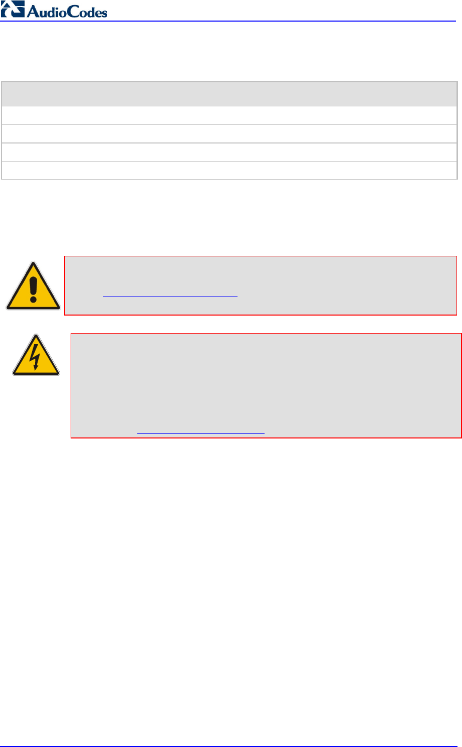
MP252 Multimedia Home Gateway 20 Document #: LTRT-23504
User's Manual
Related Documentation
Document Name
Demo Guide
Multimedia Home Gateway Quick Guide
Release Notes
Routing Performance Technical Application Note
Safety Warnings
Note: Open source software may have been added and/or amended for this product.
For further information please visit our website at:
http://audiocodes.com/support or contact your AudioCodes sales
representative.
Warning: Before connecting MP252 to power:
• Use only the AC/DC power adapter supplied with MP252. Do not use any
other power adapter. This power adapter is a 12 VDC +/-10%, tolerance,
2A, limited power source wall-mount Class II power supply adapter.
• Ensure that the VAC ratings match.
• Ensure that you have read the Regulatory Information, obtained from
www.audiocodes.com/library.

MP252 Multimedia Home Gateway 1. Introduction
Version 3.4.0 21 June 2011
For Customers in Canada
This Class [B] digital apparatus complies with Canadian ICES-003.
Cet appareil numérique de la classe [B] est conforme à la norme NMB-003 du Canada.
Operation is subject to the following two conditions: (1) this device may not cause interference,
and (2) this device must accept any interference, including interference that may cause
undesired operation of the device.
This device and its antenna(s) must not be co-located or operating in conjunction with any other
antenna or transmitter.
The County Code Selection feature is disabled for products marketed in the US/Canada.
IC Radiation Exposure Statement
This equipment complies with IC RSS-102 radiation exposure limits set forth for an uncontrolled
environment. This equipment should be installed and operated with minimum distance of 20 cm
between the radiator and your body.

MP252 Multimedia Home Gateway 22 Document #: LTRT-23504
User's Manual
Reader’s Notes

MP252 Multimedia Home Gateway 1. Introduction
Version 3.4.0 23 June 2011
1 Introduction
The MediaPack™ 252 (MP252) is a sophisticated, feature-rich, multimedia home gateway
for broadband networks with multi-play support. With ADSL2+ modem, multiple antenna
wireless LAN connectivity, Digital Enhanced Cordless Telecommunications (DECT)
handsets supporting High Definition (HD) Voice-over-IP (VoIP), and optional battery backup,
this is a true all-in-one gateway for Multi-play services.
The MP252 is ideal for operators, seeking new revenue generators with state-of- the-art
features, such as:
ADSL/ADSL2+ modem, up to 24 Mbps
10/100 Ethernet WAN port (optional connection to cable modem or FTTH ONU)
Optional ADSL WAN backup using 3G USB dongles
HD VoIP telephony and PBX capabilities, including flexible configuration of individual
SIP accounts per DECT extension
Four 10/100 Ethernet LAN ports
High-speed wireless network (802.11 b/g/n), up to 150 Mbps
Router, Firewall, NAT and advanced traffic prioritization mechanisms
2 FXS ports for analog phones and fax machines
Guaranteed Quality of Service (QoS) for IPTV service
Print server and File server, accessible from every computer on the home network
Advanced TR-069 management, interoperable with leading Auto-Configuration Servers
(ACS)
Optional battery backup for up to 4 hours standby
The MP252 is based on AudioCodes’ MP-2xx line of Residential Gateways and AudioCodes
VoIPerfect™ software architecture. The MP252 is interoperable with various softswitches
and supports advanced TR-069 management, working with market leading
Auto-Configuration Servers (ACS). Other management tools, such as a friendly HTTP-based
Web GUI, and Command Line Interface (CLI) are also available.
The MP252 is available in the following models:
Table 1-1: MP252 Available Models
Model ADSL + 4 LAN
Wi-Fi 802.11n
DECT HD VoIP
VoIP 2 FXS USB 2.0
MP252BW √ √ - √ 1
MP252WDNB √ √ √ √ 3
Note: All DECT and PBX--related functionalities are supported only by the
MP252WDNB.
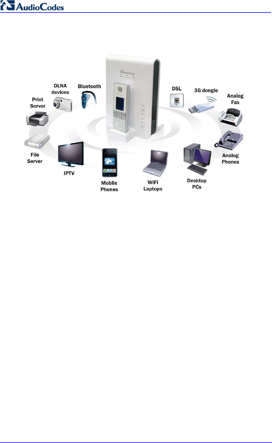
MP252 Multimedia Home Gateway 24 Document #: LTRT-23504
User's Manual
The figure below illustrates the typical applications supported by MP252:
Figure 1-1: MP252 Typical Application

MP252 Multimedia Home Gateway 2. Package Contents and Prerequisites
Version 3.4.0 25 June 2011
2 Package Contents and Prerequisites
The MP252 is shipped with the following items:
1 x RJ-11 telephone cable
1 x RJ-45 Ethernet cable
12V AC/DC power adaptor (use only supplied)
DECT handset and cradle
Make sure that all these items are included. If any items are missing, contact your sales
representative.
The following prerequisites are required (not supplied by AudioCodes):
A broadband Internet connection
ADSL cable (if required)
Analog telephones
Additional RJ-11 telephone cable (if required)
Additional RJ-45 Ethernet cables (if required)

MP252 Multimedia Home Gateway 26 Document #: LTRT-23504
User's Manual
Reader’s Notes
MP252 Multimedia Home Gateway 3. Hardware Description
Version 3.4.0 27 June 2011
3 Hardware Description
This section describes the physical description and cabling of the MP252. This includes both
models (i.e., MP252BW and MP252WDNB).
3.1 Physical Description
The MP252 provides ports, buttons, and LEDs on its front and rear panels.
3.1.1 Front Panel
The front panel provides LEDs for displaying various operating status and button(s) for
activating various features such as Wi-Fi. For more information on the LEDs, see Section
3.1.1.2 on page 29. For more information on the buttons, see Section 3.1.1.1 on page 28.
The figures below display the front panels of the MP252 models.
Figure 3-1: Front Panel of MP252BW
WiFi Button
LEDs
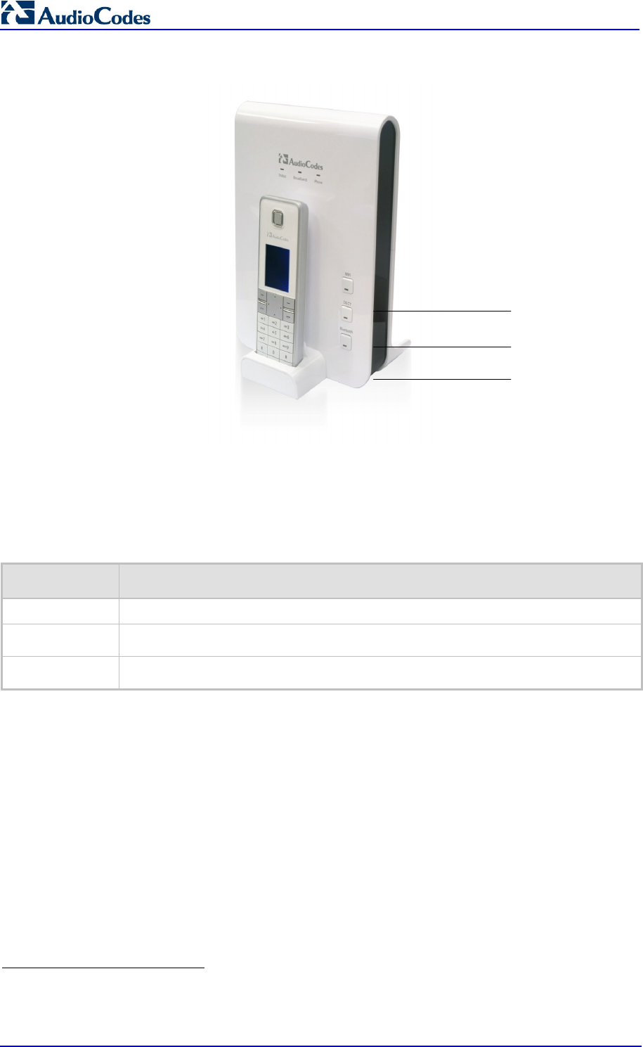
MP252 Multimedia Home Gateway 28 Document #: LTRT-23504
User's Manual
Figure 3-2: Front Panel of MP252WDNB
3.1.1.1 Front-Panel Buttons Description
The button(s) on the front panel are described in the table below:
Table 3-1: Front-Panel Buttons Description
Label Description
WiFi Activates or deactivates Wi-Fi connectivity (802.11 b/g/n).
Dect
1
Registers the handset to the MP252 base unit.
Bluetooth
2
Currently not supported.
1
This button is available only on the MP252WDNB model.
2
This button is available only on the MP252WDNB model.
WiFi Button
DECT Button
Bluetooth
Button

MP252 Multimedia Home Gateway 3. Hardware Description
Version 3.4.0 29 June 2011
3.1.1.2 Front-Panel LEDs Description
The LEDs on the front panel are described for general functionality and for the Automatic
Dialer feature.
3.1.1.2.1 General Description
The general description of the MP252 front-panel LEDs are described in the table below:
Table 3-2: Front-Panel LEDs Description
LED Color State Description
On Device start-up successful
Slow Blinking
Software upgrade in progress.
Note:
During software upgrade, the Broadband and Phone
LEDs also blink green.
Slow Blinking
Battery backup is in use and there is no power from the AC
electrical outlet.
Green
Fast Blinking
Battery is low and there is no power from the AC electrical
outlet.
Status
Red On Reboot (automatic, by default) or indicates a problem
On WAN port is successfully connected and IP address
acquired successfully
Green
Blinking Software upgrade in process
Red
On WAN IP address has not yet been acquired from the ISP
(i.e. in the process of acquiring or has failed to acquire).
Broadband
- Off WAN Ethernet cable is not connected – no WAN link
On All configured phones are registered to the Proxy server
Green
Blinking Software upgrade in process
Red On At least one of the phones failed to register to the Proxy
server
Phone
- Off No Proxy server is configured
Green
On Wi-Fi is enabled and active
WiFi
Red Off Wi-Fi is disabled
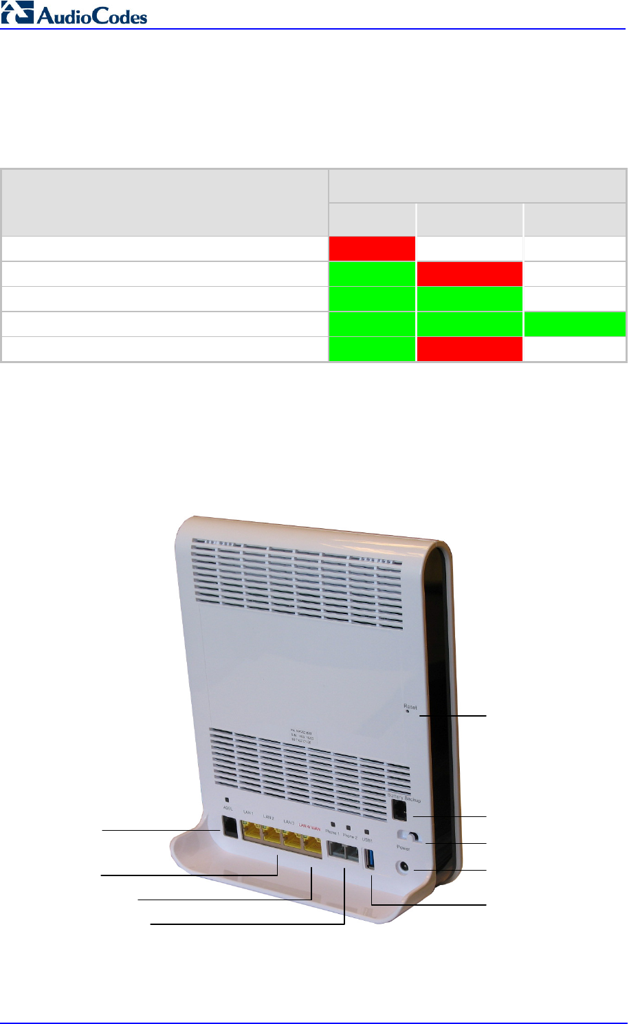
MP252 Multimedia Home Gateway 30 Document #: LTRT-23504
User's Manual
3.1.1.2.2 Automatic Dialer Feature
The table below describes the front-panel LEDs behavior when the Automatic Dialer feature
is used (described in detail in Section 7.2).
Table 3-3: Front-Panel LED Descriptions for Automatic Dialer Feature
LED Stage
Status Broadband Phone
During boot Red Off Off
Before WAN physical link detection Green Blinking Red
Off
During automatic dialer operation Green Blinking Green
Off
Automatic dialer success Green Green Green*
Automatic dialer failure Green Red Off
* The Phone LED lights green only after MP252 connects to the Internet, downloads its
configuration file, and then registers to the VoIP service.
3.1.2 Rear Panel
The rear panel provides the ports for connecting the various interfaces. The figures below
display the rear panels of the MP252 models.
Figure 3-3: Rear Panel of MP252BW
Reset
Button
Battery Backup Port
Power Plug
FXS Phone Ports
LAN/WAN Port
ADSL Port
LAN Ports
USB Plug
Power Button
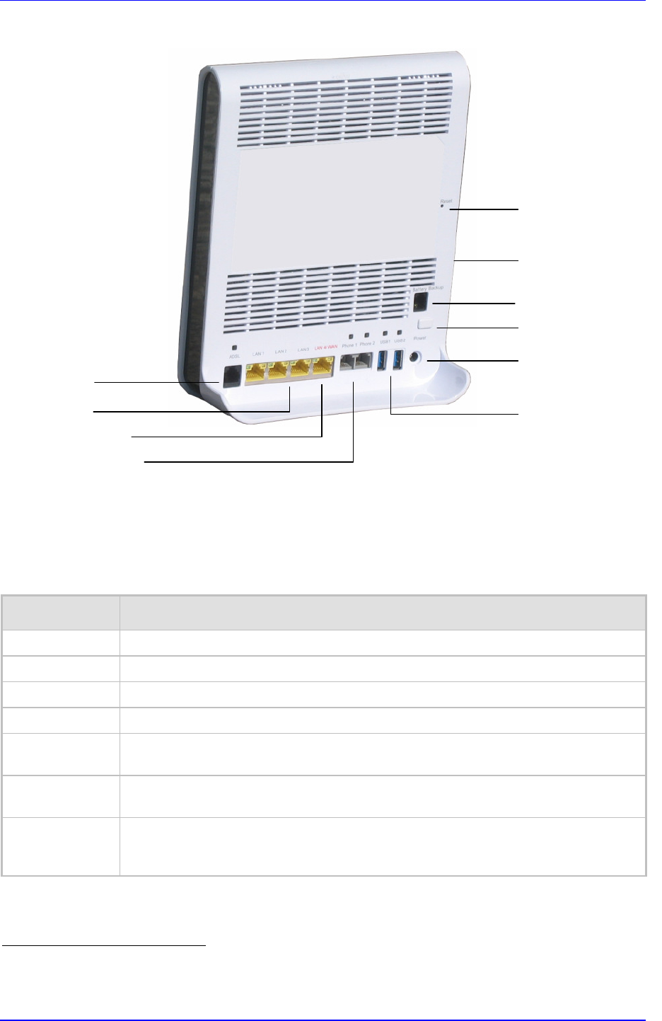
MP252 Multimedia Home Gateway 3. Hardware Description
Version 3.4.0 31 June 2011
Figure 3-4: Rear Panel of MP252WDNB
3.1.2.1 Rear-Panel Port Description
The ports of the rear panel are described in the table below:
Table 3-4: Rear-Panel Ports Description
Label Description
ADSL RJ-11 port for connecting ADSL/ADSL2+ modem (up to 24 Mbps)
LAN 3 x RJ-45 10/100Base-T Ethernet LAN ports
LAN/WAN 1 x RJ-45 10/100Base-T Ethernet LAN or Ethernet WAN port
Phone 2 x RJ-11 FXS ports for connecting analog phones and fax machines
USB
3
USB Type A port for print or file servers, or for optional WAN backup using a 3G USB
dongle
Power Power plug for connecting the supplied AC/DC power adapter. A button is located
above this port to switch on the MP252.
Battery Backup
Port for connecting an optional battery backup, providing up to four hours standby
power. (The external battery backup system connects to this port and the Power
plug using a splitter cable.)
3
The MP252WDNB model provides two USB ports in this location.
Reset
Button
Battery Backup Port
Power Plug
USB (3) Plug
FXS Phone Ports
LAN/WAN Port
ADSL Port
LAN Ports
USB (1 & 2)
Plugs
Power Button
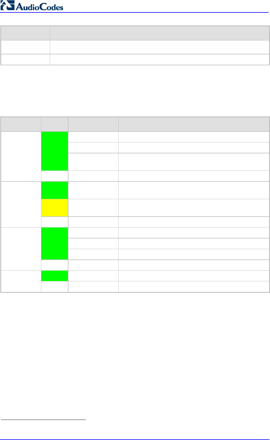
MP252 Multimedia Home Gateway 32 Document #: LTRT-23504
User's Manual
Label Description
USB3
4
USB port (located on the side panel, as shown in Figure 3-4).
Reset Reset pin button for resetting the MP252.
3.1.2.2 Rear-Panel LEDs Description
The LEDs on the rear panel are described in the table below:
Table 3-5: Rear-Panel LEDs Description
LED Color State Description
On ADSL physical link is up
Slow Blinking ADSL link is synchronizing
Green
Fast Blinking ADSL attempting to train (establishing a connection with
the Internet Service Provider)
ADSL
- Off No physical ADSL link
Green
Blinking LAN / WAN connection sending / receiving data at 100
Mbps
Yellow
Blinking LAN / WAN connection sending / receiving data at 10
Mbps
LAN / WAN
- Off No LAN / WAN traffic or Ethernet cable is disconnected
On Phone is off-hook
Slow Blinking Phone is ringing
Green
Fast Blinking MP252 is currently being upgraded
Phone
- Off Phone is on-hook and not ringing
Green
On USB device is connected
USB
- Off No USB device is connected
4
This USB port is available on the MP252WDNB model.
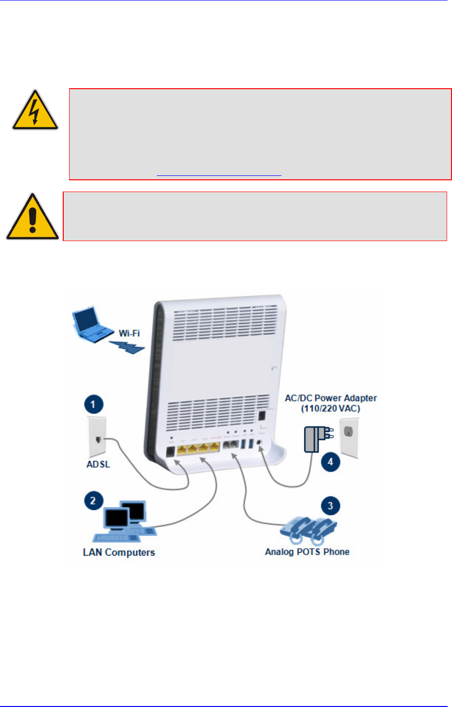
MP252 Multimedia Home Gateway 3. Hardware Description
Version 3.4.0 33 June 2011
3.2 Cabling
The procedure below describes the cabling of the MP252.
Warning:
• Use only the AC/DC power adapter supplied with MP252. Do not use
any other power adapter.
• Ensure that the VAC ratings match.
• Ensure that you have read the MP252 Regulatory Information, obtained
from www.audiocodes.com/library.
Note: The cabling procedures for the MP252 models are identical and therefore, no
distinction is made between the models in this section. However, for
convenience, this section uses the MP252WDNB model as an example.
The figure below displays a summary of the cabling procedures.
Figure 3-5: Cabling MP252
MP252 Multimedia Home Gateway 34 Document #: LTRT-23504
User's Manual
To cable MP252:
1. Connect MP252 to the Internet. The cabling depends on the Internet connection:
• ADSL: connect the ADSL port (located on the rear panel and labeled ADSL) to the
telephone socket, using an RJ-11 telephone cable.
• WAN Ethernet: connect the LAN4/WAN port (located on the rear panel and
labeled LAN 4/WAN) to an external modem, using a CAT-5 Ethernet cable.
Note: Use minimum 26 AWG wire for cabling the ADSL port to the public switched
telephone network (PSTN).
2. Connect the LAN Ethernet ports (labeled LAN 1 - 4) to your LAN computers, using
RJ-45 CAT-5 Ethernet cables.
3. Connect the telephone ports (labeled Phone 1 - 2) to analog telephones, using RJ-11
telephone cables.
4. Connect MP252 to a standard 110/220 VAC electrical wall outlet, using the supplied
AC/DC power adapter.
When MP252 is powered on, the Status LED is lit. After initialization completes (about two
minutes), this LED changes from red to green. If no power is received by
MP252, press the Power button located on the rear panel to switch it on.
3.3 Mounting
You can place MP252 on a desktop or mount it on a wall. For desktop mounting, MP252
provides integrated rubber feet on its base so that it sits firmly on a desktop. Alternatively,
you can hang your MP252 on a wall, using the supplied MP252 wall-mounting bracket, as
described in this section.
Wall mounting consists of the following main procedural stages:
Preparing the mounting screws on the wall
Hanging the mounting bracket on the wall
Attaching MP252 to the mounting bracket
Before you begin, ensure that you have the following items:
Wall-mounting bracket (supplied)
2 x screws
2 x wall anchors
Screwdriver
Note: When choosing a wall on which to mount MP252, consider cable limitations and
wall structure.
To wall-mount MP252:
1. Prepare the wall-mounting screws:
a. Drill two holes in the wall according to the wall-mounting bracket dimensions. The
vertical distance between the holes should be 83 mm (3.27 inches).
b. Insert a wall anchor into each hole.
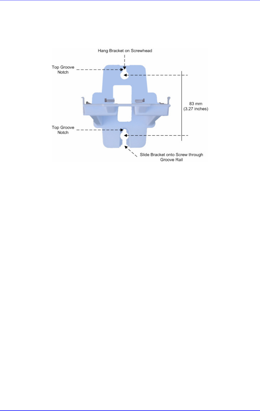
MP252 Multimedia Home Gateway 3. Hardware Description
Version 3.4.0 35 June 2011
c. Using a screwdriver, drive screws of the appropriate size into the anchors, leaving
approximately 4 mm (0.16 inches) of the screw head jutting out. This protrusion will
allow you to hang the mounting bracket on the screw head.
Figure 3-6: MP 252 Wall Mount Bracket
2. Hang the mounting bracket on the wall screws:
a. Gently slide the mounting bracket onto the lower screw so that the screw enters the
bracket's bottom screw groove rail. As you lower the bracket onto the screw,
ensure that the upper screw fits into the bracket's top screw groove.
b. Gently pull down on the mounting bracket so that both screw heads sit firmly and
securely in the top notch of the screw grooves.
3. Attach MP252 to the wall-mounting bracket:
a. Three slits at the base (bottom) of MP252 are covered by rubber caps. Remove
these caps.
b. With its rear panel facing the mounting bracket, hold MP252 at an angle and slide
the base of MP252 under the two latches located on the mounting bracket.
c. Align the three slits on the MP252 base with the three protruding humps located on
the front of the mounting bracket. Align the clip holes on either side of MP252 with
the clips on the mounting bracket.
d. While gently pressing down on MP252, press the clips inwards so that the clips
snap into the base of MP252.

MP252 Multimedia Home Gateway 36 Document #: LTRT-23504
User's Manual
Figure 3-7: Attaching Phone Base to Wall Mount
If for any reason, you want to remove MP252 from the wall, follow the procedure below:
To dismount MP252 from the wall:
1. Press the mounting bracket clips inwards.
2. Lift the MP252 base off the mounting bracket.

Part I
Gateway Configuration
Part I describes the configuration of the MP252 router and VoIP functionality analog, and
includes the following chapters:
Setting up an Internet Connection
Using MP252's Web Interface
Configuring VoIP Parameters
Connecting MP252 to a VoIP Service Provider
Making VoIP Calls
Quality of Service (QoS)
LAN Connection
WAN Connection
Editing Network Connections and Advanced Configuration
VLAN Settings
LAN-WAN Bridge Settings
Remote MP252 Management
Security
Advanced Settings
System Monitoring

Reader’s Notes
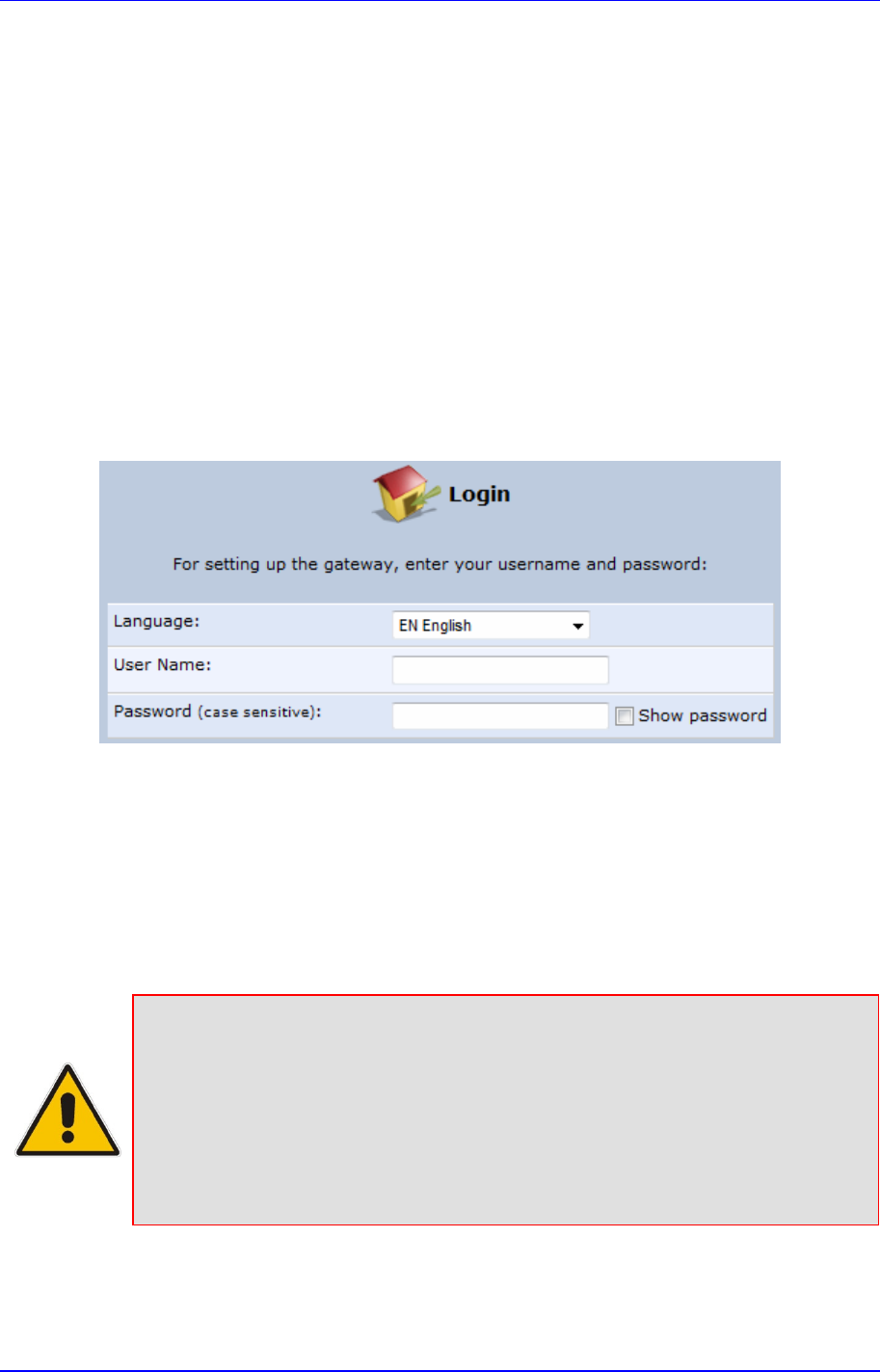
Version 3.4.0 39 July 2011
MP252 Multimedia Home Gateway 4. Getting Started with the Web Interface
4 Getting Started with the Web Interface
The MP252 embedded Web server (Web interface) provides a user-friendly Web-based
management tool that allows you to configure and monitor MP252. This chapter describes
how to access, navigate in, and configure parameters with the Web interface.
4.1 Logging in to the Web Interface
The procedure below describes how to log in to the MP252 Web interface.
To log in to the MP252 Web interface:
1. Connect a PC directly to the LAN port (labeled LAN 1) of the MP252.
2. On your PC, open a Web browser (e.g., Internet Explorer) and in the URL field, enter
http://mp252.home (or 192.168.2.1). If your MP252 is already connected to the
network and you know its IP address, then enter its IP address instead. The ‘Login’
screen appears:
Figure 4-1: Login Screen
3. From the ‘Language’ drop-down list, select the desired language for the Web graphical
user interface (GUI) display.
4. In the 'User Name' and 'Password' fields, define a login username and password,
respectively. This is applicable only if this is your first time that you are logging in to the
Web interface. If you have logged in before, then enter the username and password that
you defined previously.
5. Click Continue; the ‘Quick Setup’ screen appears, allowing you to quickly set up an
Internet connection (as described in Chapter 5 on page 55).
Notes:
• The default username and password is "admin" (case-sensitive).
•
If you wish to view the entered password (instead of asterisks), then select
the ‘Show password’ check box.
•
You can later change the username and password as described in Section
4.4 on page 331.
• If the Web interface is inactive for 15 minutes after logging in, the ‘Login’
screen appears again, prompting you to re-login.
MP252 Multimedia Home Gateway 40 Document #: LTRT-23504
User's Manual
4.2 Menu Bar Description
The Web interface screens are conveniently grouped into related themes under specific
menus. These menus are located in the menu bar. The table below describes these menus.
Table 4-1: Menu Description
Menu Description
Home Displays the Map View (refer to Section 5 on page 55).
Quick Setup
Displays the 'Quick Setup' screen for quickly setting up an Internet connection with
MP252 (see Section 7.1 on page 63).
Network
Connections
Displays the 'Network Connections' screen for configuring network connections:
LAN (see Chapter 12.2 on page 151)
WAN (see Chapter 12 on page 131)
VLANs (see Chapter 12.4 on page 181)
LAN-WAN bridging (see Section 12.5 on page 188)
Security Displays the 'Security' screen for configuring security-related features such as
Website restrictions (see Chapter 14 on page 225).
Voice Over IP Displays the 'Voice Over IP' screen for configuring the VoIP parameters to use
MP252's VoIP functionality to place and receive calls over the Internet using a
standard telephone set and DECT handset (see Chapter8 on page 77).
QoS
Displays the 'Quality Of Service' screen for configuring Quality of Service (QoS) for
MP252 (see Chapter 11 on page 113).
Advanced Displays the 'Advanced' screen for configuring system parameters (e.g., DHCP
server and DNS) and for administrative functions (e.g., changing password, setting
date and time, and upgrading the system).
Icon Name Description
About MP252 Displays technical information about MP252,
including version number (see Section 18.1
on page 310).
Backup and
Restore
Backup user and system data (see Section
18.2 on page 311).
Certificates Manages digital certificates (see Section 13.3
on page 200).
Configuration
File
Loads the Configuration File to MP252 (see
Section 18.4 on page 316).
Note: You can hide the Configuration File
icon, by running the following CLI command in
a Telnet session with MP252:
rg_conf_set
rmt_config/hide_config_file_page
1. This is useful, for example, in scenarios
where you want to prevent a user accessing
the Web interface to change the configuration
file.
MP252 Multimedia Home Gateway 4. Getting Started with the Web Interface
Version 3.4.0 41 June 2011
Menu Description
DNS Server Alias a dynamic IP address to a static
hostname (see Section 15.2 on page 257).
Diagnostics
Performs networking diagnostics (see Section
19.1 on page 334).
Disk
Management
Manages different disks connected to MP252
(see Section 17.2 on page 272).
File Server Creates a file server on MP252 (see Section
17.1 on page 270).
Firmware
Upgrade
Upgrades the MP252 firmware (see Section
18.5 on page 323).
IP Address
Distribution
Modifies the DHCP server for each LAN
device and displays a list of DHCP clients in
the local network (see Section 15.1 on page
251).
Network
Objects
Defines groups of LAN devices for system
rules (see Section 4.5.2 on page 50).
PPPoE Relay
Enables PPPoE relay on MP252 (see Section
15.5 on page 262).
Personal
Domain Name
(Dynamic
DNS)
Displays and modifies the DNS hosts table
(see Section 15.2 on page 257).
Print Server Shares a LAN printer (see Section 17.3 on
page 286).
Protocols Manages protocols (see Section4.5.3 on
page 51).
Reboot Restarts MP252 (see Section 18.6 on page
329).
Regional
Settings
Modifies the regional settings (see Section
8.10 on page 105).
Remote
Administration
Configures remote administration privileges
(see Section 13.2 on page 197).
Restore
Factory
Settings
Restores default factory settings (see Section
18.8 on page 333).
MP252 Multimedia Home Gateway 42 Document #: LTRT-23504
User's Manual
Menu Description
Routing Manages routing policies (see Section 15.4
on page 261).
Scheduler Defines time segments for system rules (see
Section 4.5.1 on page 47).
Simple
Network
Management
Protocol
(SNMP)
Configures MP252's SNMP agent (see
Section 13.2 on page 197).
System
Settings
Modifies administrator settings, including the
MP252 host name (see Section 15.5 on page
262).
Time Settings
Configures the local date and time (see
Section 18.2 on page 311).
Universal Plug
and Play
Configures Universal Plug-and-Play (UPnP)
parameters (see Section 16.1 on page 265).
Users Configures Users (see Section 4.4 on page
44).
WINS Server Registers host names and IP addresses of
WINS clients (see Section Error! Reference
source not found. on page Error!
Bookmark not defined.).
System
Monitoring
Displays the 'System Monitoring' screen for viewing various statuses such as
network and traffic statistics (see Chapter 16 on page 265).
Logout Logs off the MP252 Web interface.
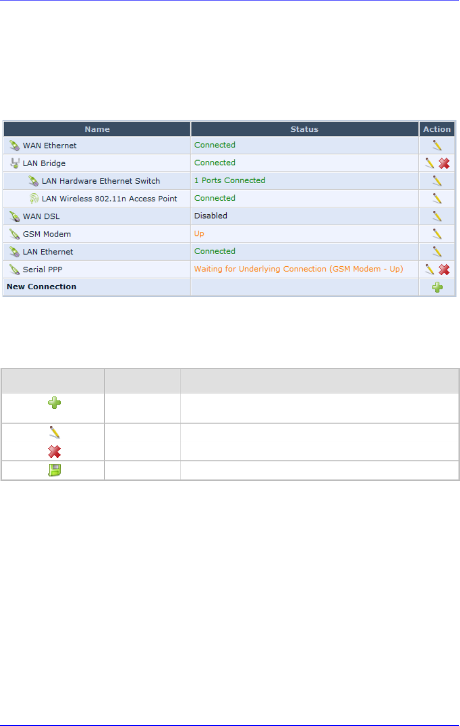
MP252 Multimedia Home Gateway 4. Getting Started with the Web Interface
Version 3.4.0 43 June 2011
4.3 Managing Tables
Tables appear throughout the Web interface for configuring MP252. This section describes
the how to use these tables to configure MP252.
The figure below displays a typical table in the Web interface:
Figure 4-2: Typical Table Structure
Each table row denotes an entry in the table. The table also provides 'Action' icons for
performing various tasks. These icons are described in the table below.
Table 4-2: Table Action Icons Description
Action Icon Name Description
New Adds a new row to the table or opens another screen for
adding an entry.
Edit Modifies a row entry in the table.
Remove Deletes a row entry in the table.
Download Downloads a file to a folder on your computer.
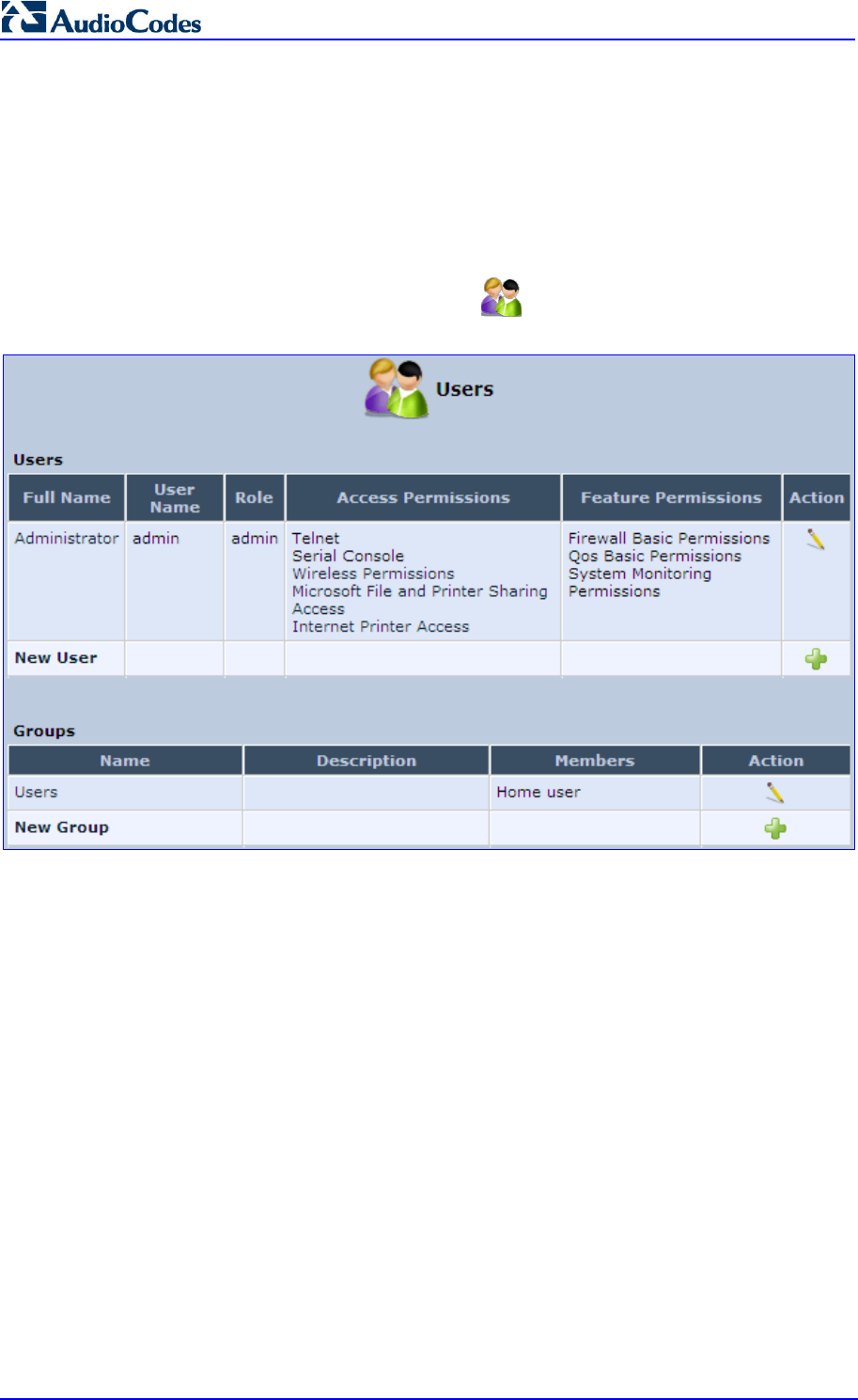
MP252 Multimedia Home Gateway 44 Document #: LTRT-23504
User's Manual
4.4 Configuring Users
The 'Users' screen allows you to add new users and assign login usernames and passwords.
You may also group users according to your preferences. The default user is "Administrator"
with "admin" (case-sensitive) as the username and password.
To configure users:
1. In the 'Advanced' screen, click the Users icon; the 'Users' screen appears.
Figure 4-3: Users Screen
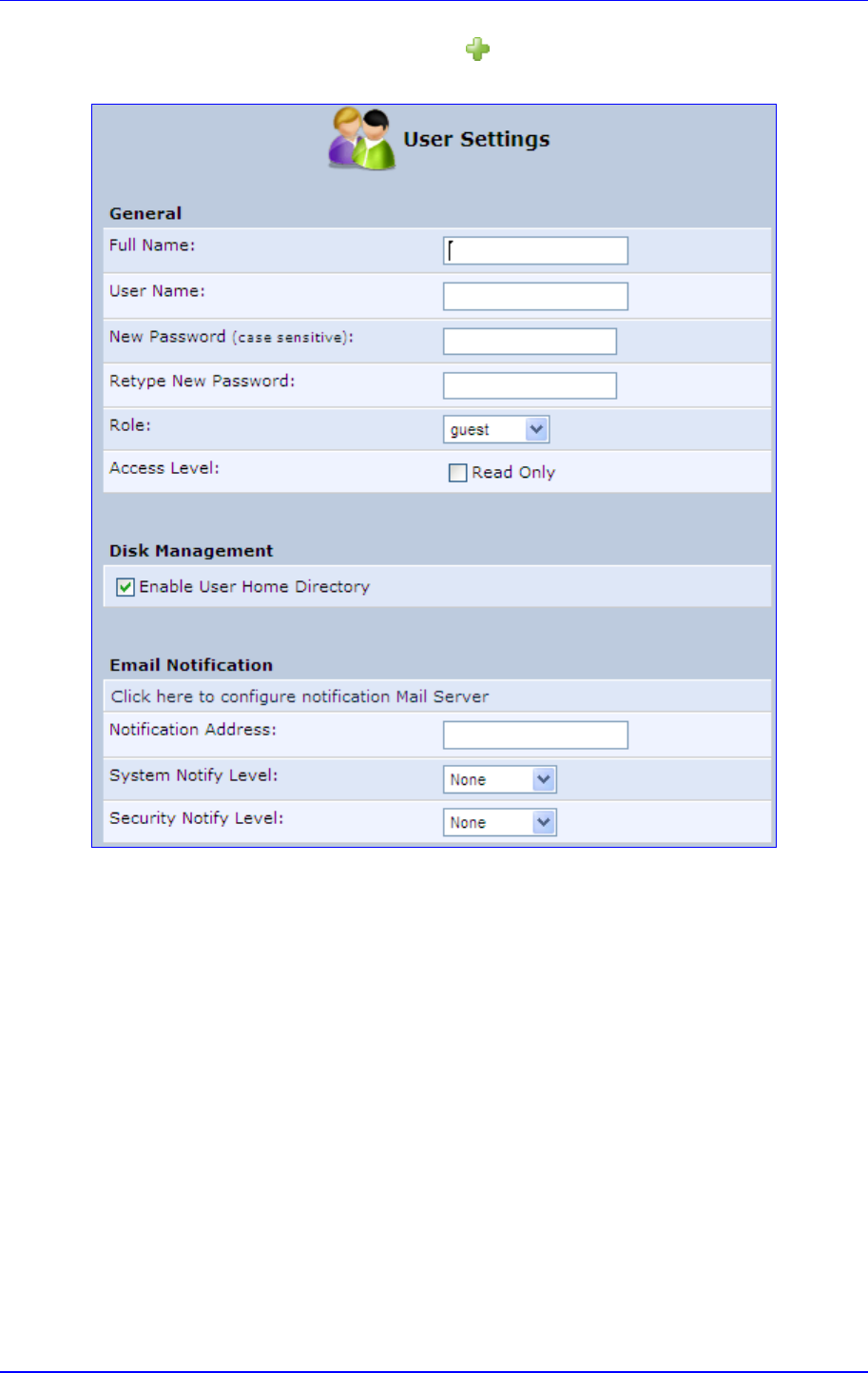
MP252 Multimedia Home Gateway 4. Getting Started with the Web Interface
Version 3.4.0 45 June 2011
2. In the Users table, click the New User icon; the 'Users Settings' screen appears.
Figure 4-4: Users Settings Screen
3. Add a new user by configuring the following fields:
a. Full Name: Enter a remote user's full name.
b. User Name: Enter a user name to access your home network.
c. New Password: Enter a new password for the remote user. If you do not want to
change the remote user's password leave this field empty.
d. Retype New Password: If a new password was assigned, enter it again to verify
correctness.
e. Role: User’s role indicating privilege level, where “admin” possesses all privileges.
f. Access Level – Read Only: Select this check box if you want this user to have
read-only privileges.
g. Disk Management: By default, this option is selected. When activated, it creates a
directory for the user in the 'Home' directory of the system storage area. This
directory is necessary when using various applications such as the mail server.
h. Email Notification: You can use email notification to receive indications of system
events for a predefined severity classification. The available types of events are
'System' or 'Security' events. The available severity of events is 'Error', 'Warning'
and 'Information. If the 'Information' level is selected, the user receives notification
of the 'Information', 'Warning' and 'Error' events. If the 'Warning' level is selected,
the user receives notification of the 'Warning' and 'Error' events etc.
MP252 Multimedia Home Gateway 46 Document #: LTRT-23504
User's Manual
♦
Click here to configure notification mail server: This opens the ‘System
Settings’ screen (see Section 15.5 on page 262) where you can define an
outgoing mail server.
♦
Notification Address: user’s email address.
♦
System Notify Level: By default, the 'None' option is selected, which means
that MP252 does not send notifications to a remote host. To activate the
feature, select one of the following notification types:
Error
Warning
Information
♦
Security Notify Level: The remote security notification level can be one of
the following:
None
Error
Warning
Information
4. Click OK.
Note: Modifying any of the user parameters prompts the connection associated with
the user to terminate. For changes to take effect, you should activate the
connection manually after modifying user parameters.
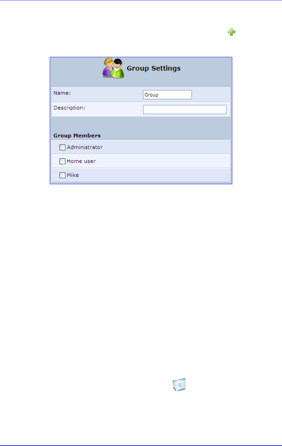
MP252 Multimedia Home Gateway 4. Getting Started with the Web Interface
Version 3.4.0 47 June 2011
To configure user groups:
1. In the 'Users' screen, under the Groups group, click New Group icon; the 'Group
Settings' screen appears.
Figure 4-5: Group Settings Screen
2. In the 'Name' field enter a name for the group.
3. In the 'Description' field, enter a brief description of this group.
4. In the 'Group Members' list, select the users that you want to assign to this group.
5. Click OK.
4.5 Defining Associated Elements
You can define certain elements and then use them later when configuring various features
throughout the Web interface. This is very convenient in that it eliminates the need to
re-configure the same element, especially if used in multiple configuration areas. These
elements include the following:
Scheduler Rules – see Section 4.5.1 on page 47
Network Objects – see Section 4.5.2 on page 50
Protocols – see Section 4.5.3 on page 51
4.5.1 Defining Scheduler Rules
Scheduler rules are used for limiting the activation of firewall rules to specific time periods,
specified in days of the week, and hours.
To define a Rule:
1. In the 'Advanced' screen, click the Scheduler icon; the 'Scheduler Rules' screen
appears.
Figure 4-6: Scheduler Rules Screen
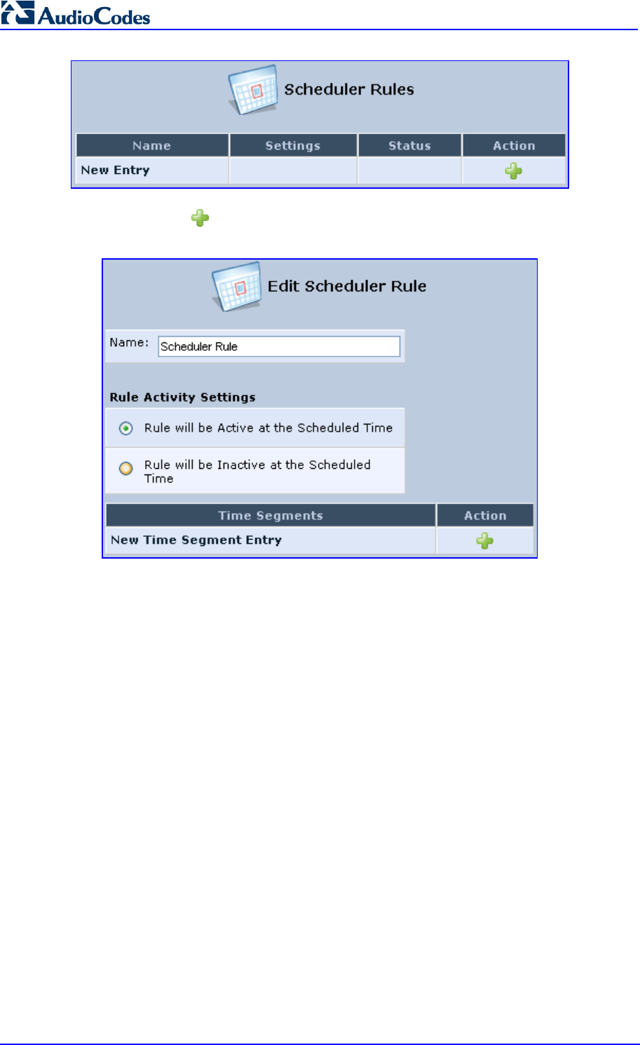
MP252 Multimedia Home Gateway 48 Document #: LTRT-23504
User's Manual
2. Click the New icon; the 'Edit Scheduler Rule' screen appears.
Figure 4-7: Edit Scheduler Rule Screen
3. In the 'Name' field, specify a name for the scheduler rule.
4. Under the Rule Activity Settings group, specify if the rule is active or inactive during
the designated time period, by selecting the appropriate check box.
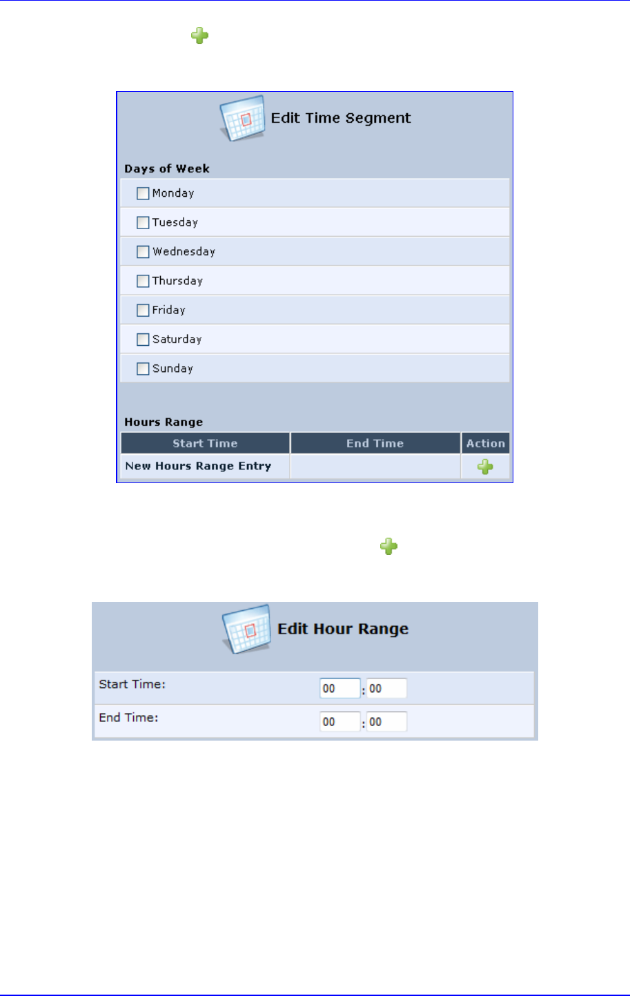
MP252 Multimedia Home Gateway 4. Getting Started with the Web Interface
Version 3.4.0 49 June 2011
5. Click the New icon to define the time segment to which the rule applies; the 'Edit
Time Segment' screen appears.
Figure 4-8: Edit Time Segment Screen
a. Under the Days of Week group, select the days of the week for which you want the
rule to be active.
b. In the Hours Range table, click the New icon to define an active or inactive
hourly range; the ‘Edit Hour Range’ screen appears.
Figure 4-9: Edit Hour Range Screen
c. In the ‘Start Time’ and ‘End Time’ field, enter the time interval in which the
scheduler rule is active or inactive.
6. Click OK to save the settings.
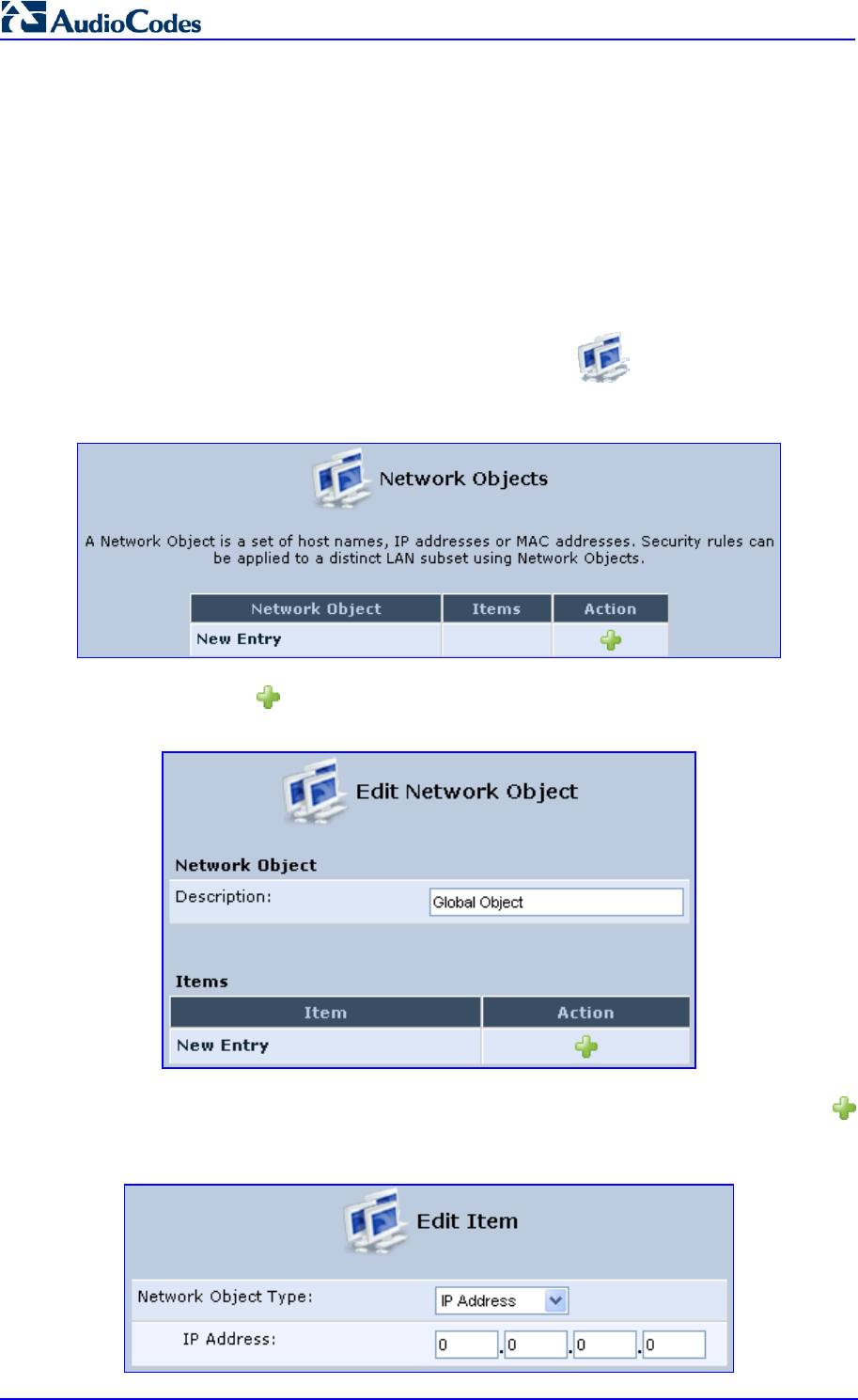
MP252 Multimedia Home Gateway 50 Document #: LTRT-23504
User's Manual
4.5.2 Defining Network Objects
Network objects is a method used to logically define a set of LAN hosts, according to one or
more MAC address, IP address, and host name. Defining such a group can assist when
configuring other system rules. For example, you can use network objects to apply security
rules based on host names instead of IP addresses. This may be useful, since IP addresses
change from time to time. Moreover, it is possible to define network objects according to
MAC addresses, making rule application more persistent against network configuration
settings.
To define a network object:
1. In the 'Advanced' screen, click the Network Objects icon; the 'Network Objects'
screen appears.
Figure 4-10: Network Objects Screen
2. Click the New icon; the 'Edit Network Object' screen appears.
Figure 4-11: Edit Network Objects Screen
3. In the 'Description' field, enter a name for the network object, and then click the New
icon; the 'Edit Item' screen appears.
Figure 4-12: Edit Item Screen

MP252 Multimedia Home Gateway 4. Getting Started with the Web Interface
Version 3.4.0 51 June 2011
4. From the 'Network Object Type' drop-down lists, select a source address type:
• IP Address
• IP Subnet
• IP Range
• MAC Address
• Host Name
• DHCP Option (supporting options 60, 61, and 77)
• All Private IP Addresses
When selecting a method from the drop-down list, the screen refreshes, presenting the
respective fields by which to enter the relevant information.
5. Click OK to save the settings.
4.5.3 Defining Protocols
The Protocols feature incorporates a list of preset and user-defined applications and
common port settings. You can use protocols in various security features such as Access
Control and Port Forwarding. You may add new protocols to support new applications or edit
existing ones according to your needs.
To define a protocol:
1. In the 'Advanced' screen, click the Protocols icon; the 'Protocols' screen appears.
Figure 4-13: Advanced - Protocols
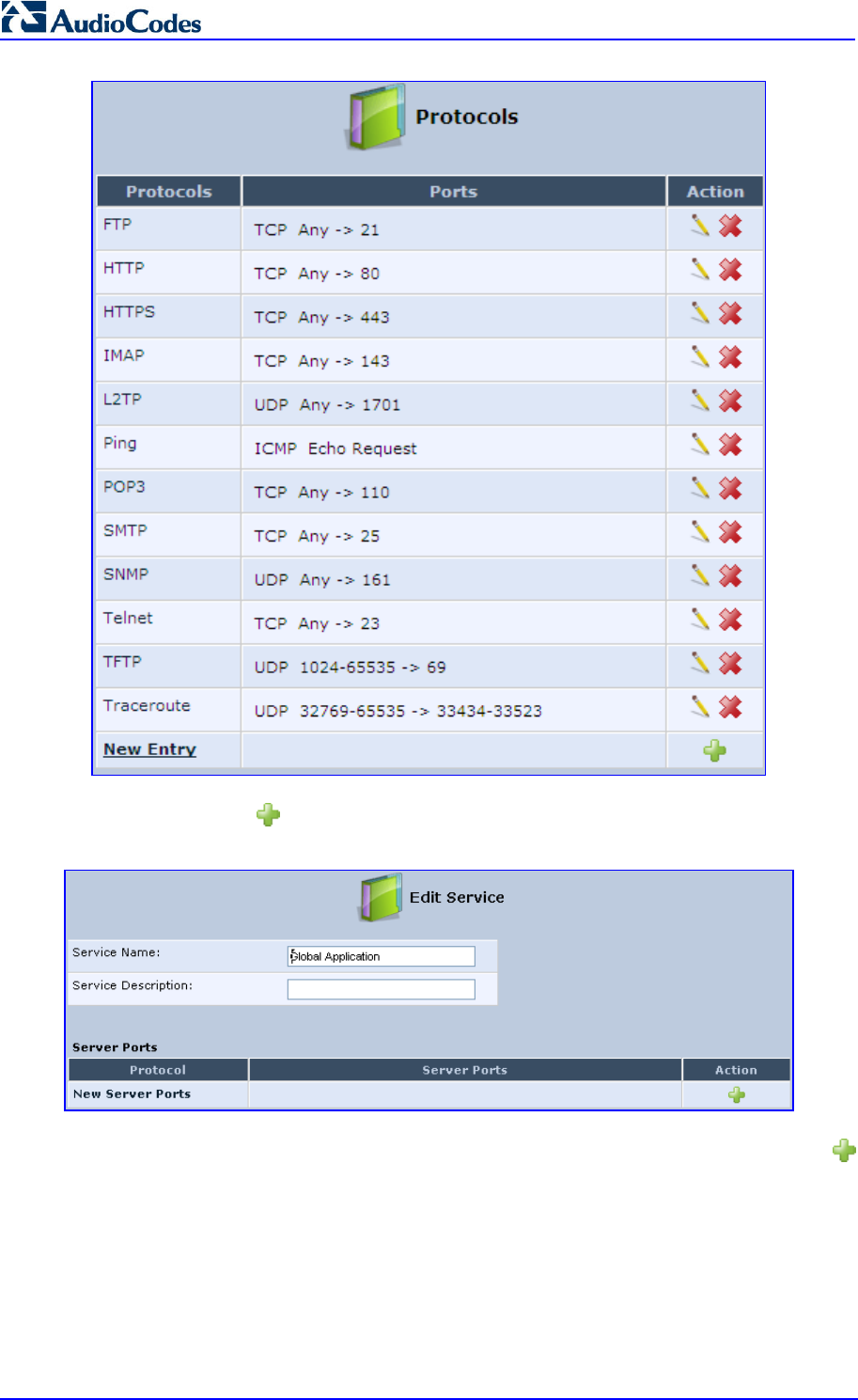
MP252 Multimedia Home Gateway 52 Document #: LTRT-23504
User's Manual
2. Click the New icon; the 'Edit Service' screen appears.
Figure 4-14: Advanced - Protocols - Edit Service
3. In the 'Service Name' field, enter the name of the service, and then click the New
icon; the 'Edit Service Server Ports' screen appears.
Figure 4-15: Advanced - Protocols - Edit Service - Server Ports
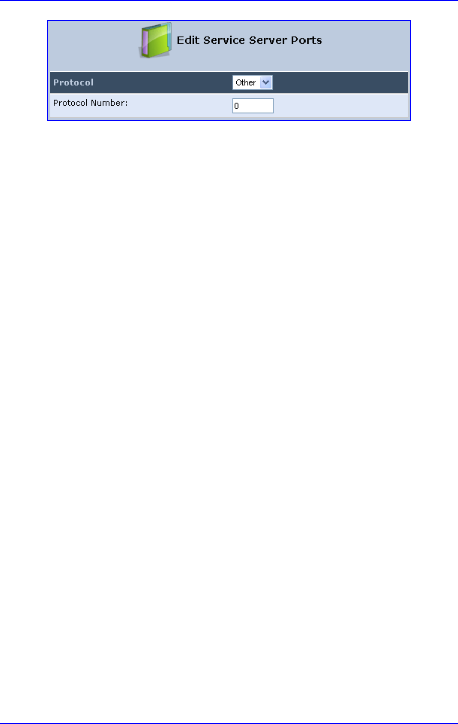
MP252 Multimedia Home Gateway 4. Getting Started with the Web Interface
Version 3.4.0 53 June 2011
4. You may choose any of the protocols available in the drop-down list, or add a new one
by selecting 'Other'. When selecting a protocol from the drop-down list, the screen
refreshes, presenting the respective fields by which to enter the relevant information.
5. Select a protocol and enter the relevant information.
6. Click OK to save the settings.
4.6 Logging out the Web Interface
To log out the MP252, click the Logout menu in the menu bar. When you logged out, the
‘Login’ screen is displayed, allowing you to re-login, if desired.

MP252 Multimedia Home Gateway 54 Document #: LTRT-23504
User's Manual

MP252 Multimedia Home Gateway 5. Viewing a Graphical Display of the MP252 Network
Version 3.4.0 55 June 2011
5 Viewing a Graphical Display of the MP252
Network
The Web interface allows you to view a graphical display of the network elements connected
to MP252. This is displayed in the ‘Map View’ screen, accessed by clicking the Home menu
in the menu bar.
You can click a displayed network element icon to access the relevant screen for configuring
the element.
The figure below displays an example of a network map for a deployed MP252:
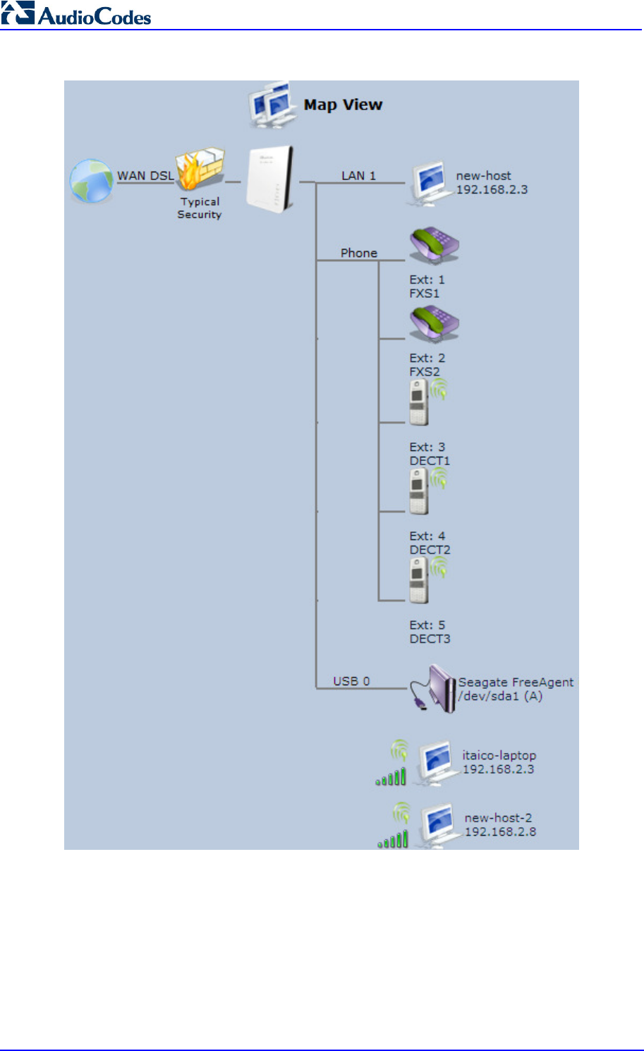
MP252 Multimedia Home Gateway 56 Document #: LTRT-23504
User's Manual
Figure 5-1: Map View Screen (Example)
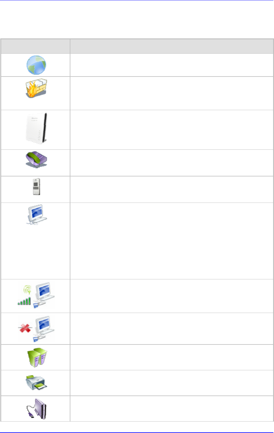
MP252 Multimedia Home Gateway 5. Viewing a Graphical Display of the MP252 Network
Version 3.4.0 57 June 2011
The table below describes the possible icons that can be displayed in the ‘Map View’ screen:
Table 5-1: Map View Icon Description
Icon Description
Depicts the Internet connection (e.g., WAN Ethernet).
Click this icon to open the 'Quick Setup' screen (see Section 7.1 on page 63).
Depicts the firewall. The height of the wall (yellow "bricks") corresponds to
the security level (Minimum, Typical or Maximum).
Click this icon to open the ‘General Tab’ screen (see Section 14.1 on page
226).
Depicts MP252 and displays the currently software version.
Click this icon to open the 'Quick Setup' screen (see Section 7.1 on page 63).
Depicts an analog telephone connected to MP252.
Click this icon to open the ‘Extension Settings’ screen (see Section 8.7 on
page 102).
Depicts a DECT handset registered to the MP252.
Click this icon to open the ‘Extension Settings’ screen (see Section 8.7 on
page 102).
Depicts a computer (host) in the MP252 network. Each computer connected
to the network appears below the network symbol of the network through
which it is connected. This host is either a DHCP client that has received an
IP lease from MP252, or a host with a static IP address, auto-detected by
MP252.
Click this icon to open the ‘Host Information’ screen, displaying network
information of the host.
Note: MP252 recognizes a physically connected host and displays it in the
Network Map only after network activity from that host has been detected
(e.g. trying to browse to the Web management or to surf the Internet).
Depicts a computer connected to the Internet through the MP252 Wi-Fi
network.
Click this icon to open the ‘Host Information’ screen, displaying network
information of the host.
Depicts a host whose DHCP lease has expired and not renewed. The DHCP
lease is renewed automatically, unless the host is no longer physically
connected to MP252. This icon also depicts a static IP host that has no
network activity.
Depicts a file server (hard drive) that is connected to MP252 (typically
through the USB port). Click this icon to view the file server configuration.
Depicts a printer that is connected to MP252 and is shared by network users.
Click this icon to view the printer's settings.
Depicts a USB driver.

MP252 Multimedia Home Gateway 58 Document #: LTRT-23504
User's Manual
Icon Description
Depicts a USB disk-on-key that is connected to MP252.
Depicts a disconnected device.
MP252 Multimedia Home Gateway 6. Configuring Computers for Connecting to the MP252 Network
Version 3.4.0 59 June 2011
6 Configuring Computers for Connecting to
the MP252 Network
This chapter describes how to configure computers to connect to the MP252 network, and
includes the following main areas:
Connecting wired computers – see Section 6.1 on page 59
Connecting wireless network computers – see Section 6.2 on page 61
6.1 Wired Computers
This section describes how to configure computers that connect to the MP252 network
through a LAN cable (i.e., wired).
You can configure the network interface of the computer using one of the following methods:
Statically define an IP address and DNS address
Automatically obtain an IP address using the MP252 embedded DHCP server
This section describes how to configure the computers network for the following operating
systems (OS):
Windows XP – see Section 0 on page 59
Linux – see Section 6.1.2 on page 60
Notes:
• It is recommended to set the computers to automatically obtain their IP
addresses (from a DHCP server).
• Refer to the Quick Installation Guide for instructions relating to installation
on a Windows™ operating system.
6.1.1 Configuring Computers Running on Windows XP
The procedure below describes how to configure a computer running on Windows XP OS to
automatically obtain its IP address (from a DHCP server, for example, MP252).
Note:
For computers running Windows, the setup procedure is generally unnecessary
as Windows' default network settings are to obtain an IP address automatically.
However, it is recommended to follow the setup procedure to verify that all
communication parameters are valid and that the physical cable connections
are correct.
To configure a computer running Windows XP for dynamic IP addressing:
1. Access 'Network Connections' from the Control Panel.
2. Right-click the Ethernet connection icon, and then choose Properties.
3. Under the General tab, select the 'Internet Protocol (TCP/IP)' component, and then
click the Properties button; the 'Internet Protocol (TCP/IP) Properties’ dialog box is
displayed.
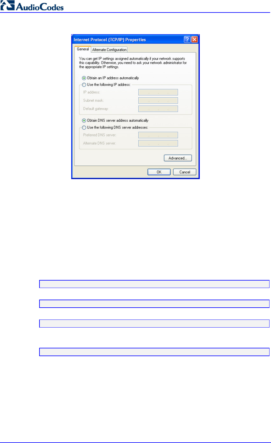
MP252 Multimedia Home Gateway 60 Document #: LTRT-23504
User's Manual
Figure 6-1: Internet Protocol (TCP/IP) Properties Dialog Box
4. Select the Obtain an IP address automatically option.
5. Select the Obtain DNS server address automatically option.
6. Click OK to save the settings.
6.1.2 Configuring Computers Running on Linux
The procedure below describes how to configure a computer running on Linux OS to
automatically obtain its IP address (from a DHCP server, for example, MP252).
To configure a computer running Linux for dynamic IP addressing:
1. Log in to the system as a super-user, by entering the following command:
su
2. View the network devices and allocated IP's, by typing the following command:
ifconfig
3. At the prompt, type the following command:
pump -i <dev>
Where <dev> is the network device name.
4. View the new allocated IP address, by typing the following command:
ifconfig
5. Make sure that no firewall is active on the device <dev>.
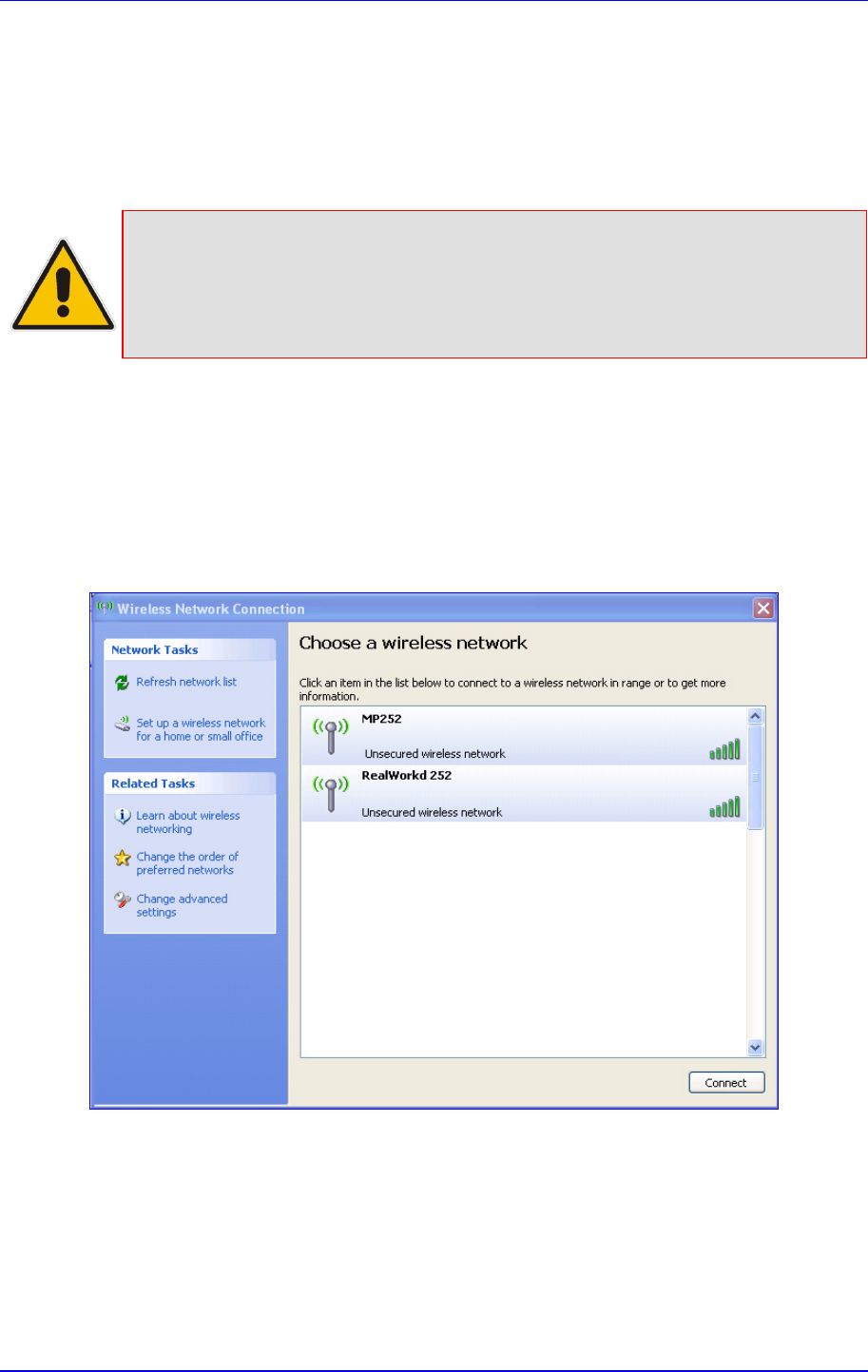
MP252 Multimedia Home Gateway 6. Configuring Computers for Connecting to the MP252 Network
Version 3.4.0 61 June 2011
6.2 Connecting PC to MP252 Wireless Networks
This section describes how to configure the LAN computers to connect to the MP252
wireless network. If your computer has wireless capabilities, Windows automatically
recognizes the MP252 wireless network and creates a wireless connection.
Notes:
• To configure the MP252 LAN wireless connection, see Section 12.2.1 on
page 151.
• This section is based on computers running Microsoft Windows XP
Professional.
To configure a computer to connect to MP252 wireless network:
1. From your Windows Start menu, point to Settings, Control Panel, Network
Connections, and then choose Wireless Connection; Windows starts enabling the
wireless connection.
2. On the Windows taskbar, right-click the Wireless Network Connection icon, and then
choose View Available Wireless Connections;
Figure 6-2: Available Wireless Networks
3. Double-click the MP252 wireless network name (i.e., "MP252"); your computer
establishes a wireless connection with MP252, indicated by the display of "Connected".

MP252 Multimedia Home Gateway 62 Document #: LTRT-23504
User's Manual
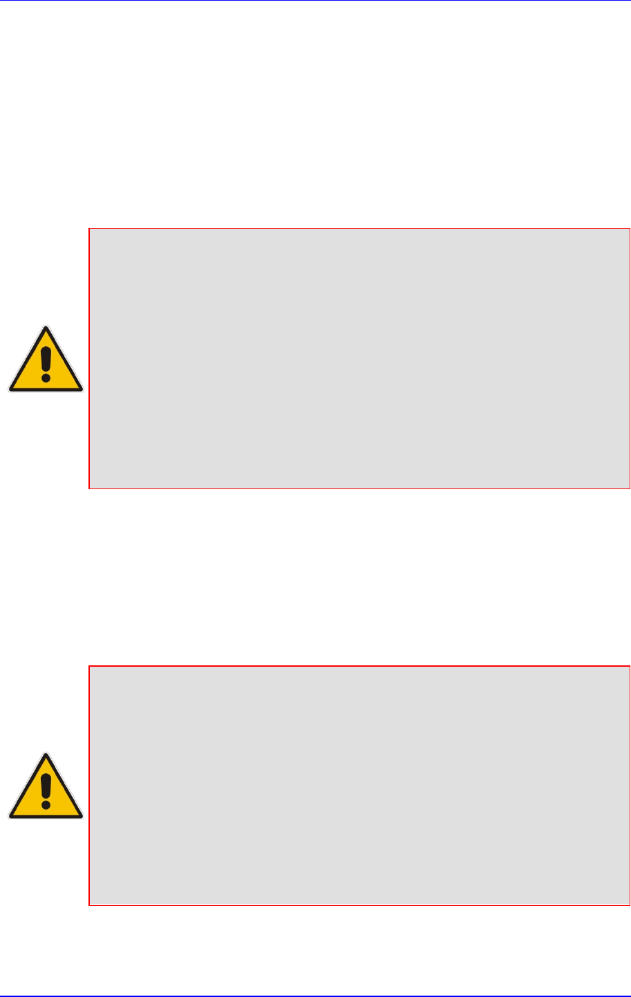
MP252 Multimedia Home Gateway 7. Connecting MP252 to the Internet
Version 3.4.0 63 June 2011
7 Connecting MP252 to the Internet
This section describes how to configure MP252 for connecting it to the Internet (WAN). You
can connect MP252 to the Internet using one of the following methods:
Configuring MP252 through the Web interface – see Section 7.1 on page 63
Using the MP252 Automatic Internet Dialer Detection feature – see Section 7.2 on page
72
Notes:
• MP252 automatically detects the physical WAN type (i.e., Ethernet or
ADSL). To change the WAN type, you must restore MP252 to factory
settings (see Section 18.8).
• When connected to ADSL, the LAN4/WAN Ethernet port can be used for
Ethernet LAN interface.
• When connected to an external modem through the Ethernet LAN4/WAN
port and MP252 obtains an IP address, the ADSL interface is disabled.
• If the Automatic Dialer
feature is shipped preconfigured (i.e., enabled), then
MP252 automatically detects the Internet dialer type and therefore, Internet
connection configuration is unnecessary. However, it is recommended to
manually configure the Internet connection after the Automatic Dialer
process has completed (successfully or not). For more information on the
Automatic Dialer feature, see Section 7.2 on page 72.
7.1 Quickly Setting up an Internet Connection in the Web
Interface
You can quickly and easily set up a basic Internet connection using the Web interface’s
'Quick Setup' screen (as shown in Figure 7-1). This screen is displayed when you log in to
the Web interface (or you can click the Quick Setup menu from the menu bar).
Notes:
• Before configuring the MP252 Internet connection, ensure that you have
obtained relevant technical information on the Internet connection type from
your Internet Telephony
Service Provider (ITSP). For example, whether you
are connected to the Internet using a static or dynamic IP address, or what
protocols such as PPTP or PPPoE are used to communicate over the
Internet.
• For advanced configuration of the WAN network, use the Network
Connections menu, as described in Section 12.1 on page 131.
• The ‘Email Address’ field in the ‘Quick Setup’ screen defines the
administrator's e-mail. System alerts and notifications are sent to this
address (typically, to the telephony carrier technicians). It is recommended
that only the administrator modify it.
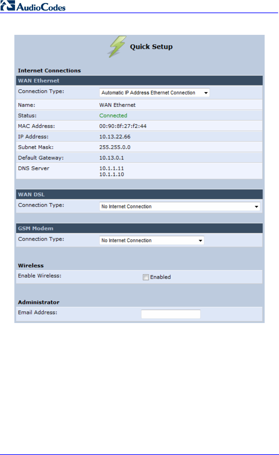
MP252 Multimedia Home Gateway 64 Document #: LTRT-23504
User's Manual
Figure 7-1: Quick Setup Screen
You can configure one of two main Internet connection types:
WAN Ethernet – see Section 7.1.1 on page 64
WAN DSL – see Section 7.1.2 on page 68
7.1.1 WAN Ethernet
MP252 supports the following WAN Ethernet connection types:
Manual IP address
Automatic IP address
Point-to-Point Protocol over Ethernet (PPPoE)
Point-to-Point Tunneling Protocol (PPTP)
Layer 2 Tunneling Protocol (L2TP)
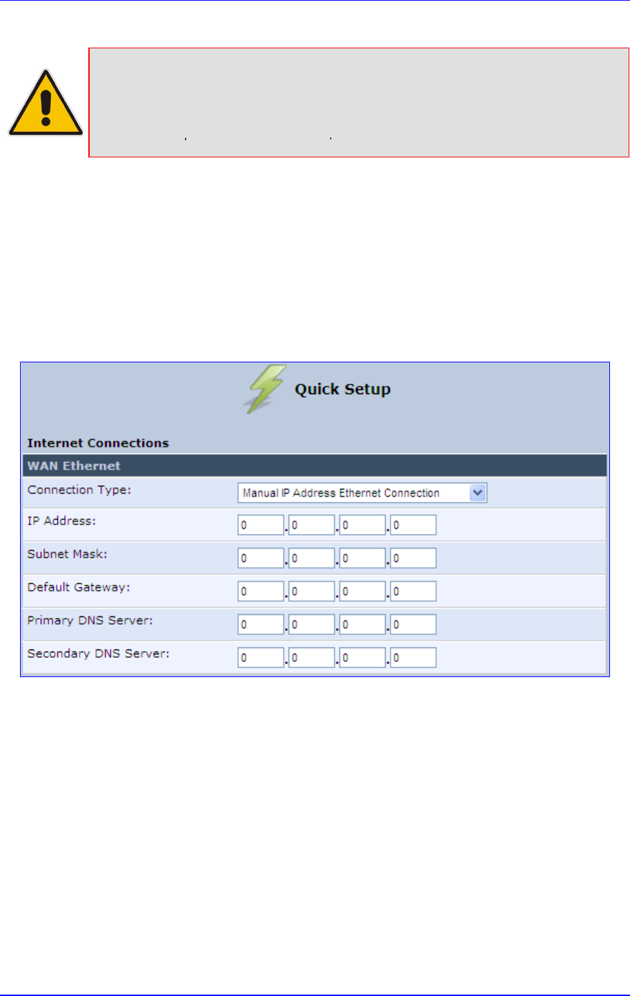
MP252 Multimedia Home Gateway 7. Connecting MP252 to the Internet
Version 3.4.0 65 June 2011
Notes:
• Automatic IP address is the default connection type.
• If you do not need an Internet (WAN Ethernet) connection, then in the
‘Quick Setup’ screen, from the ‘Connection Type’ drop-down list, select
No Internet Connection .
7.1.1.1 Manual IP Address Ethernet Connection
The procedure below describes how to connect to the Internet using a manually defined IP
address.
To configure a manual IP address connection:
1. Under the WAN Ethernet group, from the 'Connection Type' drop-down list, select
'Manual IP Address Ethernet Connection'.
Figure 7-2: Manual IP Address WAN Ethernet Connection
2. According to your ISP's instructions, specify the following parameters:
• IP address
• Subnet mask
• Default Gateway
• Primary DNS server
• Secondary DNS server
7.1.1.2 Automatic IP Address Ethernet Connection
The procedure below describes how to connect to the Internet by automatically obtaining a
WAN IP address and DNS IP address from a DHCP server on the WAN. This method is the
default connection type.
To configure automatic IP address connection:
Under the WAN Ethernet group, from the 'Connection Type' drop-down list, select
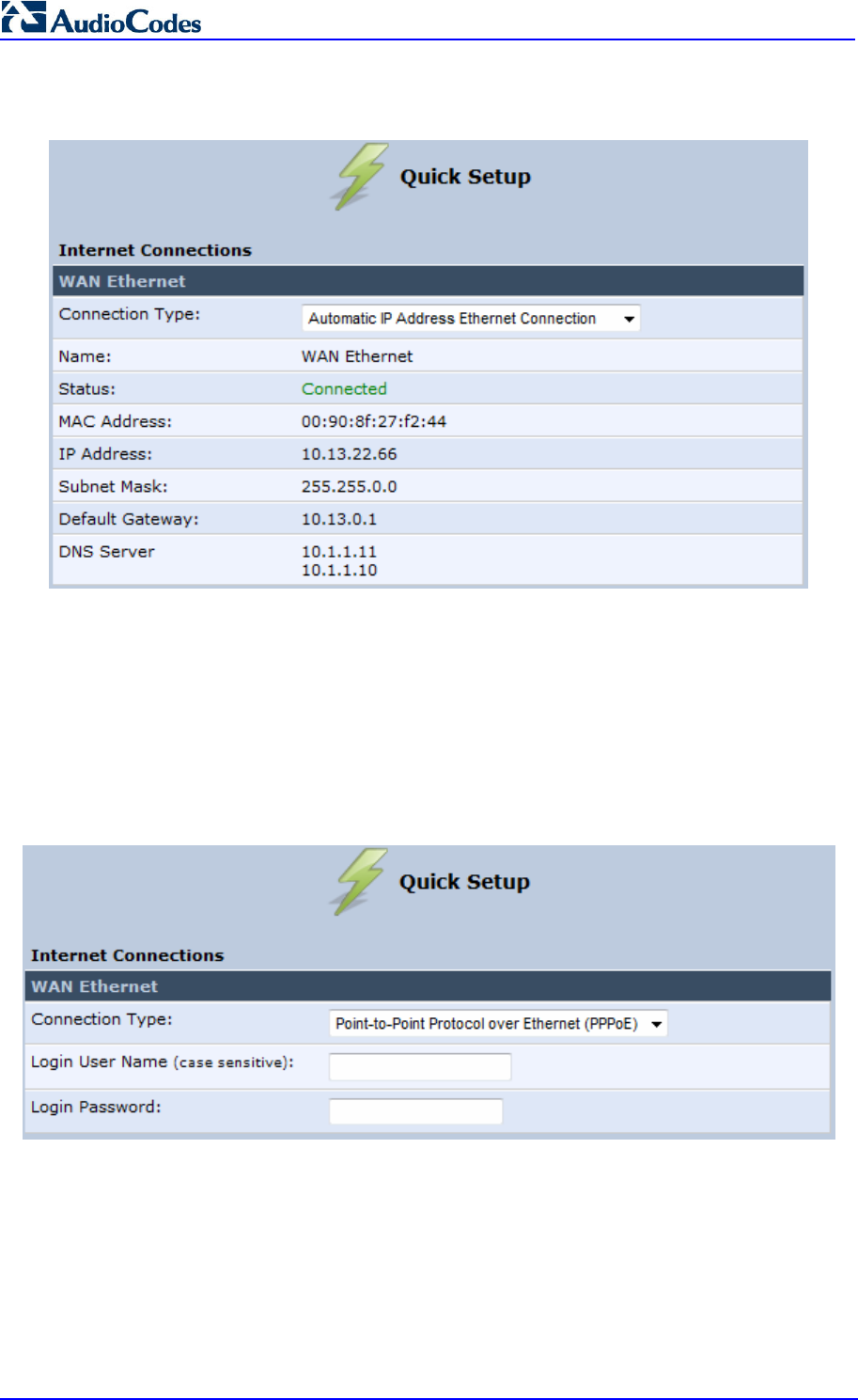
MP252 Multimedia Home Gateway 66 Document #: LTRT-23504
User's Manual
‘Automatic IP Address Ethernet Connection'.
Figure 7-3: Automatic IP Address WAN Ethernet Connection
7.1.1.3 PPPoE
The procedure below describes how to connect to the Internet by PPPoE
To configure PPPoE connection:
1. Under the WAN Ethernet group, from the 'Connection Type' drop-down list, select
'Point-to-Point Protocol over Ethernet (PPPoE)'.
Figure 7-4: PPPoE WAN Ethernet Connection
2. Configure the PPPoE login username and password (provided by your ITSP).
7.1.1.4 PPTP
The procedure below describes how to connect to the Internet by PPTP.
To configure PPTP connection:
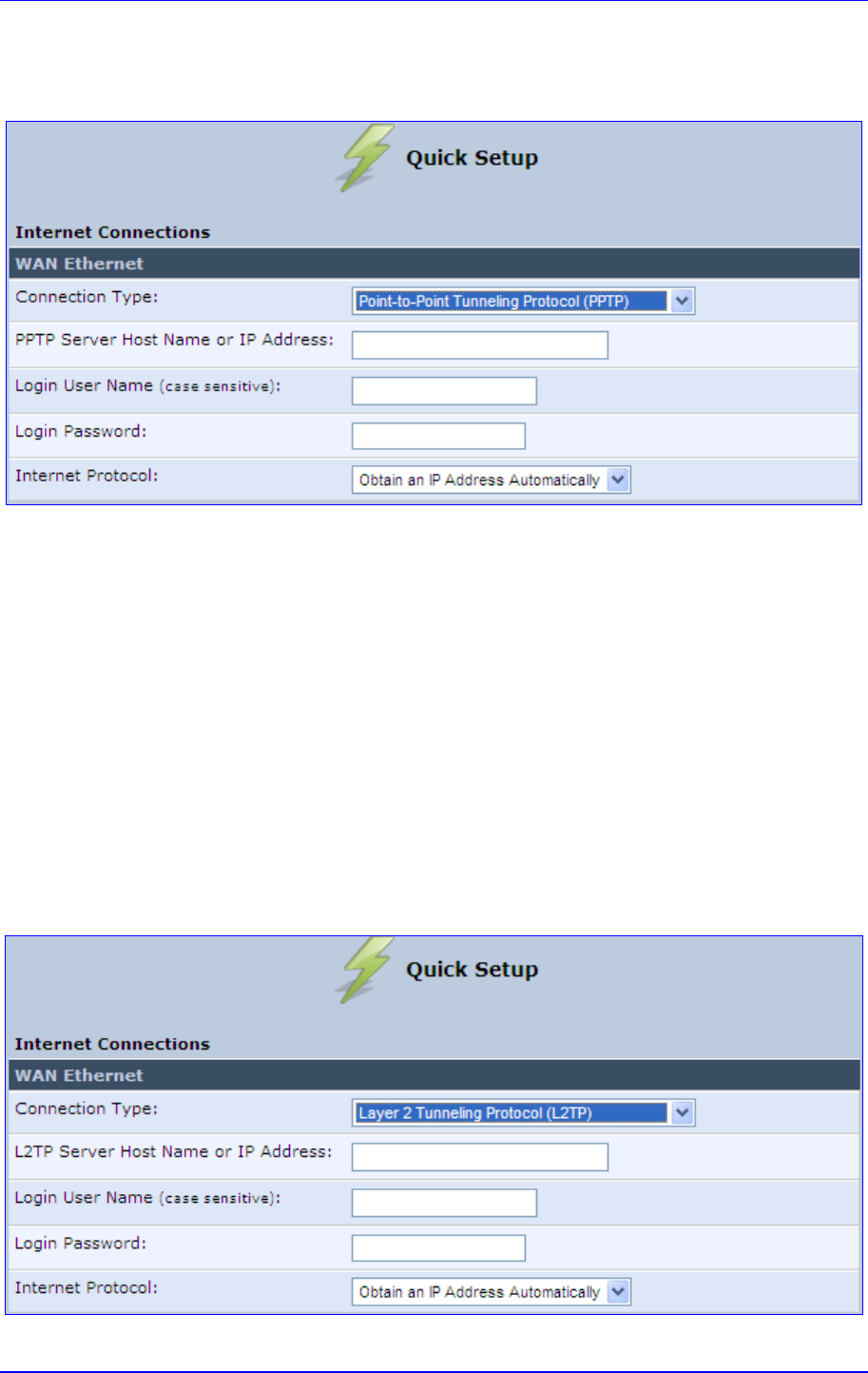
MP252 Multimedia Home Gateway 7. Connecting MP252 to the Internet
Version 3.4.0 67 June 2011
1. Under the WAN Ethernet group, from the 'Connection Type' drop-down list, select
'Point-to-Point Tunneling Protocol (PPTP)'.
Figure 7-5: PPTP WAN Ethernet Connection
2. Configure the following (provided by your ITSP):
• PPTP Server Host Name or IP Address
• Login user name
• Login password
3. From the ‘Internet Protocol’ drop-down lists, select the method for assigning an IP
address (provided by your ITSP).
7.1.1.5 L2TP
The procedure below describes how to connect to the Internet by L2TP.
To configure L2TP connection:
1. Under the WAN Ethernet group, from the 'Connection Type' drop-down list, select
'Layer 2 Tunneling Protocol (L2TP)'.
Figure 7-6: L2TP WAN Ethernet Connection
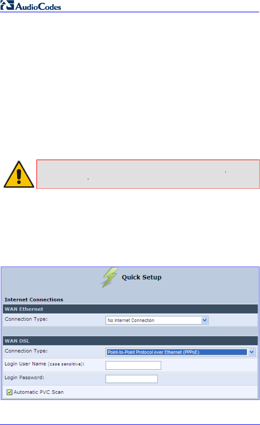
MP252 Multimedia Home Gateway 68 Document #: LTRT-23504
User's Manual
2. Configure the following (provided by your ITSP):
• L2TP Server Host Name or IP Address
• Login user name
• Login password
3. From the ‘Internet Protocol’ drop-down lists, select the method for assigning an IP
address (provided by your ITSP).
7.1.2 WAN DSL
MP252 supports the following WAN DSL connection types:
PPPoE
Point-to-Point Protocol over ATM (PPPoA)
Routed Ethernet Connection over ATM (Routed ETHoA)
LAN-WAN Bridged Ethernet Connection over ATM (Bridged ETHoA)
Classical IP over ATM (CLIP)
Note: If you do not need an Internet (WAN DSL) connection, then in the ‘Quick Setup’
screen, from the ‘Connection Type’ drop-down list, select No Internet
Connection .
7.1.2.1 PPPoE
The procedure below describes how to connect to the Internet by PPPoE.
To configure PPPoE connection:
1. Under the WAN DSL group, from the 'Connection Type' drop-down list, select
'Point-to-Point Protocol over Ethernet (PPPoE)'.
Figure 7-7: PPPoE WAN DSL Internet Connection
2. Configure the following (provided by your ITSP):
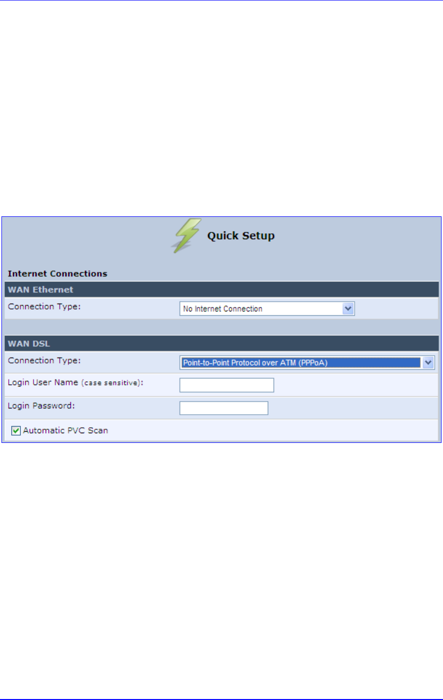
MP252 Multimedia Home Gateway 7. Connecting MP252 to the Internet
Version 3.4.0 69 June 2011
• Login user name
• Login password
3. By default, the 'Automatic PVC Scan' check box is selected, which means that MP252
configures the VPI, VCI, and encapsulation parameters automatically. To configure
these parameters manually, clear this check box (for more information, see Section
12.1.1.1 on page 133).
7.1.2.2 PPPoA
The procedure below describes how to connect to the Internet by PPPoA.
To configure PPPoA connection:
1. Under the WAN DSL group, from the 'Connection Type' drop-down list, select
'Point-to-Point Protocol over ATM (PPPoA)'.
Figure 7-8: PPPoA WAN DSL Internet Connection
2. Configure the following (provided by your ITSP):
• Login user name
• Login password
3. By default, the 'Automatic PVC Scan' check box is selected, which means that MP252
configures the VPI, VCI, and encapsulation parameters automatically. To configure
these parameters manually, clear this check box (for more information, see Section
12.1.1.1 on page 133).
7.1.2.3 Routed ETHoA
The procedure below describes how to connect to the Internet by ETHoA.
To configure routed ETHoA connection:
1. Under the WAN DSL group, from the 'Connection Type' drop-down list, select ‘Routed
Ethernet Connection over ATM (Routed ETHoA)'.
Figure 7-9: Routed ETHoA WAN DSL Internet Connection
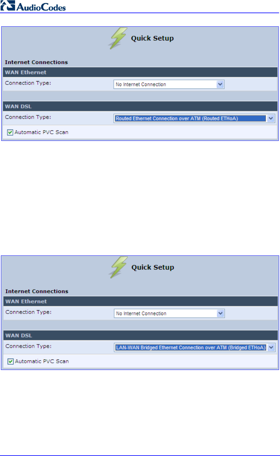
MP252 Multimedia Home Gateway 70 Document #: LTRT-23504
User's Manual
2. By default, the 'Automatic PVC Scan' check box is selected, which means that MP252
configures the VPI, VCI, and encapsulation parameters automatically. To configure
these parameters manually, clear this check box (for more information, see Section
12.1.1.1 on page 133).
7.1.2.4 Bridged ETHoA
The procedure below describes how to connect to the Internet by bridged ETHoA.
To configure bridged ETHoA connection:
1. Under the WAN DSL group, from the 'Connection Type' drop-down list, select
‘LAN-WAN Bridged Ethernet Connection over ATM (Bridged ETHoA)'.
Figure 7-10: Bridged ETHoA WAN DSL Internet Connection
2. By default, the 'Automatic PVC Scan' check box is selected, which means that MP252
configures the VPI, VCI, and encapsulation parameters automatically. To configure
these parameters manually, clear this check box (for more information, see Section
12.1.1.1 on page 133).
7.1.2.5 CLIP
The procedure below describes how to connect to the Internet by CLIP.
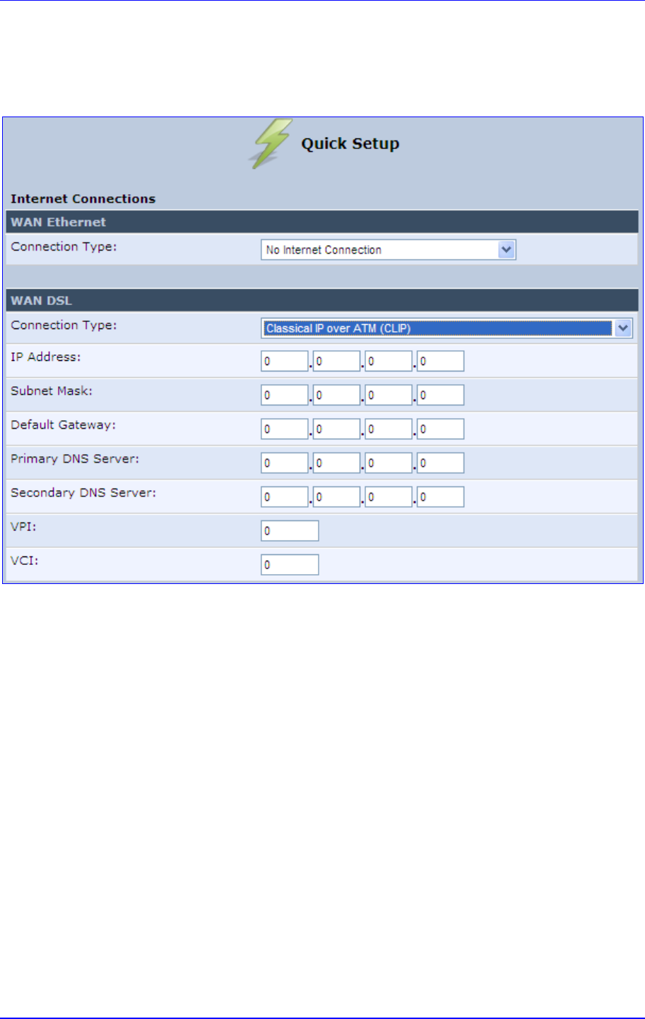
MP252 Multimedia Home Gateway 7. Connecting MP252 to the Internet
Version 3.4.0 71 June 2011
To configure CLIP connection:
1. Under the WAN DSL group, from the 'Connection Type' drop-down list, select ‘Classical
IP over ATM (CLIP)'.
Figure 7-11: CLIP WAN DSL Internet Connection
2. Configure the following (provided by your ITSP):
• IP Address
• Subnet Mask
• Default Gateway IP address
• Primary DNS Server IP address
• Secondary DNS Server IP address
• VPI
• VCI
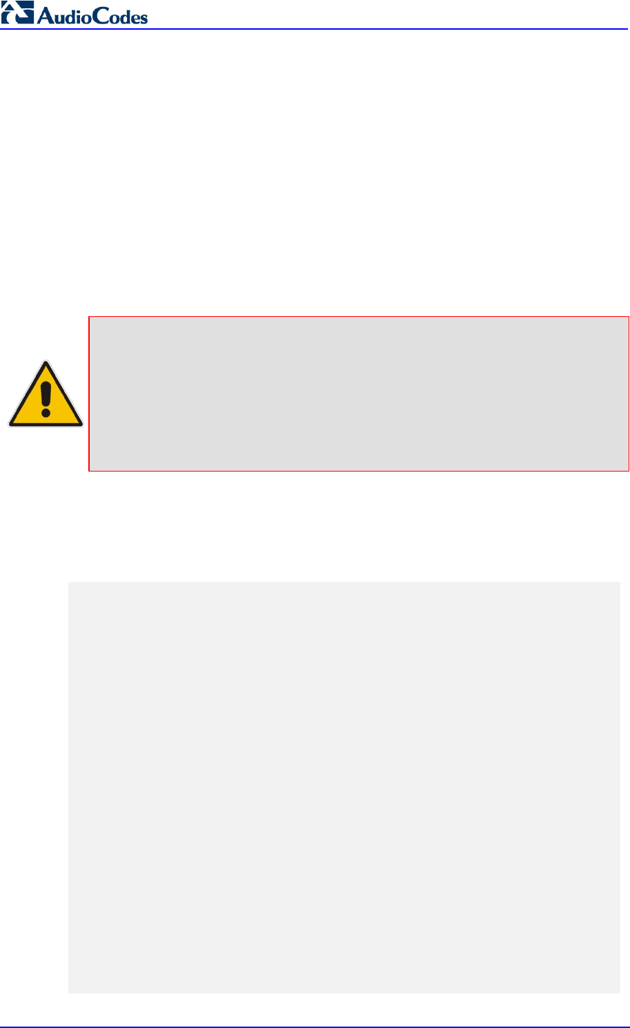
MP252 Multimedia Home Gateway 72 Document #: LTRT-23504
User's Manual
7.2 Using the Automatic Dialer for Internet Connection
The Automatic Dialer feature allows the service provider to use one type of pre-configured
MP252 for all the following Internet connection types:
WAN Ethernet (DHCP, LT2P or PPPoE)
WAN ADSL (PPPoE)
In the Private Labeling process, the factory setting is burned with the parameters of the
different dialers. When powered-up at the customer site, MP252 first detects the physical
WAN type (ADSL or Ethernet) and then attempts the relevant WAN connection methods.
The indication for a successful result is connection (i.e., receipt of an IP address) and a ping
test.
This section describes the recommended process for using the Automatic Dialer.
Notes:
• If the Automatic Dialer feature is shipped pre-configured (i.e., enabled),
then MP252 automatically detects the Internet dialer type and therefore,
configuration of the Internet connection is not necessary. However, it is
recommended to manually configure the Internet connection after the
Automatic Dialer process has completed (successfully or not).
• If you manually configure the Internet connection in the Web interface, the
Automatic Dialer feature becomes disabled.
7.2.1 Recommended Configuration
The recommended factory settings for the Automatic Dialer feature are shown below:
(auto_dialer_detect
(enabled(1))
(done(0))
(connection_type
(0
(type(DHCP))
(enabled(1))
(max_dialer_conn_time(20))
)
(1
(type(L2TP))
(enabled(1))
(server_ip(<Server Name or IP>))
(username(<User Name>))
(password(<Password>))
(max_dialer_conn_time(120))
)
(2
(type(PPPOE))
MP252 Multimedia Home Gateway 7. Connecting MP252 to the Internet
Version 3.4.0 73 June 2011
(enabled(1))
(username(<User Name>))
(password(<Password>))
(max_dialer_conn_time(120))
)
)
(auto_detect_retries(15))
(ping_retries(4))
(ping_retries_timeout(2))
(ADSL
(vpi(8))
(vci(48))
(encap(LLC))
)
)
(system
(network
(internet_url(<Address or Domain Name for Ping Test>))
)
)
Note: If the ADSL section in the factory settings is omitted, the MP252 performs an
automatic PVC scan. When configuring manual PVC values (VPI and VCI), the
connection is faster.
.
MP252 Multimedia Home Gateway 74 Document #: LTRT-23504
User's Manual
7.2.2 Setting up and Starting the Automatic Dialer
The procedure below describes how to setup and start the Automatic Dialer feature.
To setup and start Automatic Dialer:
1. Power off the MP252.
2. Connect the ADSL or Ethernet cables.
Note: If you are using an ADSL connection, DO NOT connect any cable to the
WAN/LAN4 port. Connecting this port causes the Automatic Dialer to fail.
3. Power on the MP252; the Automatic Dialer begins its operation and you can view the
progress status by checking the MP252 LEDs (see Section 3.1.1.2.2 on page 30).
Notes:
• If the connection is ADSL, the Automatic
Dialer usually connects in the first
iteration (after less than 10 seconds, when configuring manual PVC). In
some cases, the Automatic Dialer may connect in the second iteration (up
to 4 minutes).
• If the connection is WAN Ethernet:
- For DHCP, the connection is fast.
- For L2TP, the connection takes up to ~2 minutes.
- For PPPoE, the connection can take up to ~4 minutes.
MP252 Multimedia Home Gateway 7. Connecting MP252 to the Internet
Version 3.4.0 75 June 2011
7.2.3 Quitting Automatic Dialer for Manual Configuration
If, for any reason, you need to manually configure the Internet connection, you first need to
stop the Automatic Dialer feature and then manually configure the connection, as described
below,
To quit Automatic Dialer and manually configure the Internet connection:
1. Power off the MP252.
2. Disconnect the WAN ADSL or Ethernet cable.
3. Power on the MP252.
4. Wait for the Automatic Dialer process to end (i.e., the Broadband LED stops blinking).
5. Log in to the MP252 Web interface.
6. Manually configure the Internet connection using the 'Quick Setup' screen (see Section
7.1 on page 63). This ensures that the Automatic Dialer feature does not re-activate
itself after the MP252 resets.
Once the MP252 successfully connects to the Internet, it downloads its configuration file from
the server.
Note: The configuration file must include the following parameter to indicate that
Automatic Dialer is no longer needed: auto_dialer_detect/done = 1.

MP252 Multimedia Home Gateway 76 Document #: LTRT-23504
User's Manual
Version 3.4.0 77 July 2011
MP252 Multimedia Home Gateway 8. Configuring VoIP Parameters
8 Configuring VoIP Parameters
The VoIP parameters are mainly configured in the 'Voice over IP' screen. This screen is
accessed by clicking the Voice over IP menu in the side menu bar. The ‘Voice over IP'
screen provides tabs for configuring the following:
Signaling protocol (i.e., Session Initiation Protocol / SIP) – see Section 8.1 on page 77
Dialing – see Section 8.2 on page 85
Media streaming – see Section 8.3 on page 90
Voice and fax – see Section 8.4 on page 91
Supplementary services – see Section 8.5 on page 95
Line settings – see Section 8.6 on page 98
Line extensions – see Section 8.7 on page 101
Speed dials – see Section 8.9 on page 104
Telephone interfaces – see Section 8.9 on page 104
In addition to the above, you can select the region in which your MP252 is located so that
your analog telephone complies with the line standards (e.g., line impedance) of the area.
For more information, see Section 8.10 on page 105.
Notes:
• By default, the Voice over IP screens initially display only basic
parameters. To view all the parameters, click the Advanced
button in the
required screen.
•
Once you have configured the VoIP parameters, you can start using your
analog telephones, as described in Chapter 10 on page 109. For using
your DECT handset(s), see Part II.

MP252 Multimedia Home Gateway 78 Document #: LTRT-23504
User's Manual
8.1 Configuring the SIP Signaling Protocol
The procedure below describes how to configure the SIP parameters.
To configure SIP parameters:
1. From the menu bar, click the Voice Over IP menu; the following screen appears:
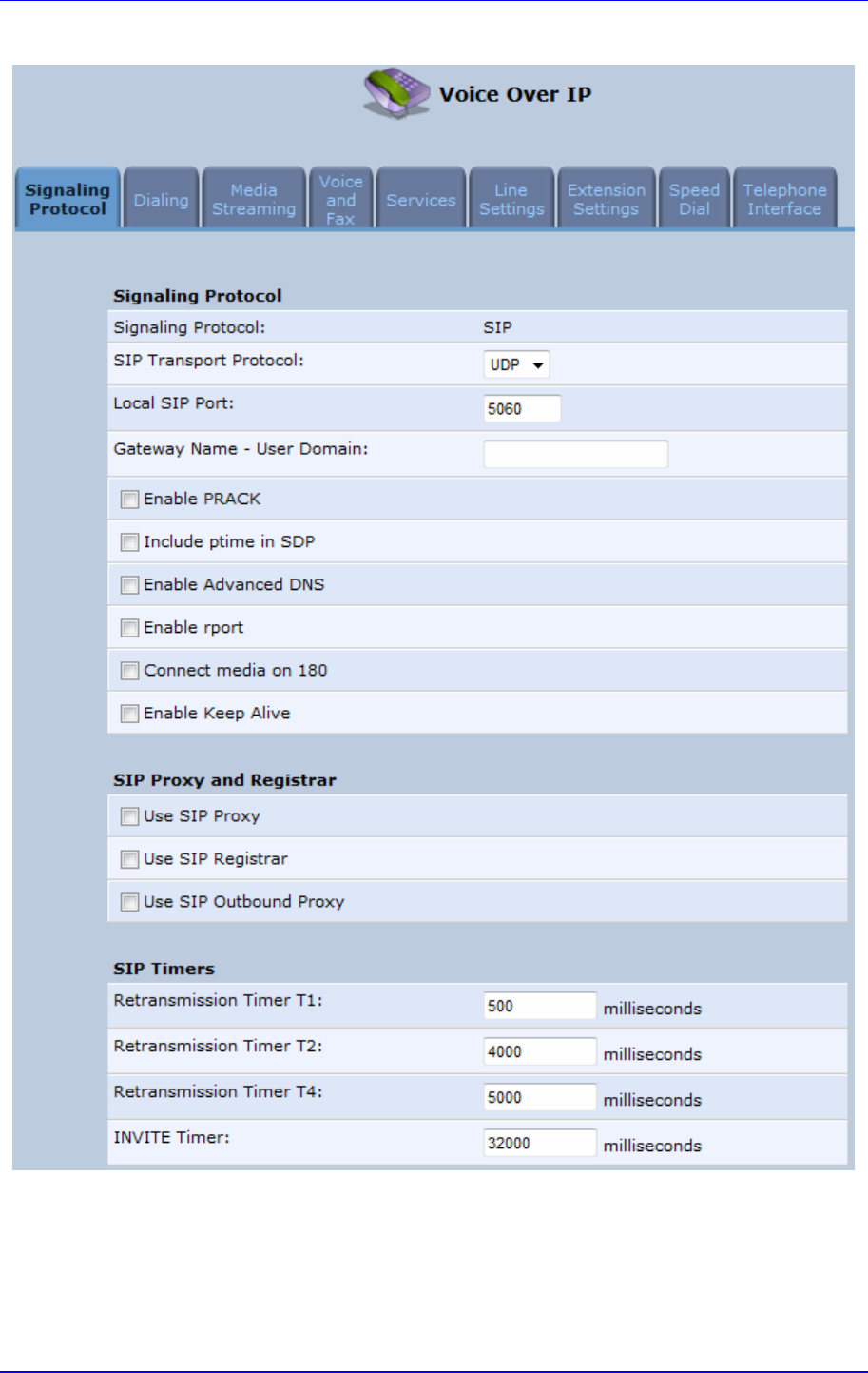
MP252 Multimedia Home Gateway 8. Configuring VoIP Parameters
Version 3.4.0 79 June 2011
Figure 8-1: Signaling Protocol Tab Screen
2. Configure the parameters, as required. For a description of the parameters displayed on
this screen, see Table 8-1.
3. Click OK to save your settings.
Table 8-1: Signaling Protocol Tab Parameters Description

MP252 Multimedia Home Gateway 80 Document #: LTRT-23504
User's Manual
Parameter Description
Signaling Protocol Group
Signaling Protocol (Read-only field.) Displays the signaling protocol running on the device.
Note: Currently, only SIP is supported.
SIP Transport Protocol Defines the SIP transport type - UDP (default), TCP, or TLS.
Note: This parameter appears only in 'Advanced' mode.
Local SIP Port
Defines the UDP / TCP port on which the SIP stack listens. The default
port is 5060.
Note: This parameter appears only in 'Advanced' mode.
Local SIP TLS Port
Defines the TLS port on which the SIP stack listens. The default port is
5060.
Note: This parameter appears only if you select ‘TLS’ as the SIP
transport protocol.
Gateway Name - User
Domain
Defines the MP252 domain name which is sent in the SIP From header
of outgoing INVITE messages.
Note: This parameter appears only in 'Advanced' mode.
Enable PRACK When enabled, MP252
replies with a PRACK message upon receipt of
a reliable provisional response. MP252 does not initiate reliable
provisional responses.
Note: This parameter appears only in 'Advanced' mode.
Include ptime in SDP When enabled, MP252 adds the ptime field to the SDP message body.
Note: This parameter appears only in 'Advanced' mode.
Enable Advanced DNS
Advanced DNS Type
Note: This parameter is available only if the ‘Enable Advanced DNS’
check box is selected.
Enable rport When enabled, MP252 adds the rport parameter to the relevant SIP
message fields.
Note: This parameter appears only in 'Advanced' mode.
Connect media on 180 When enabled, media is connected upon receipt of SIP 180, 183, or
200 messages. When this parameter is disabled, media is connected
upon receipt of 183 and 200 messages only.
Note: This parameter appears only in 'Advanced' mode.
Enable Keep Alive When enabled, a keep-alive notification is sent every user-defined
interval to the SIP registrar server.
Note: This parameter appears only in 'Advanced' mode.
Keep-Alive Type The type of keep-alive mechanism sent to the SIP registrar:
•
Using SIP OPTIONS: sends SIP OPTIONS messages
•
Using an Empty UDP packet: sends empty UDP packets
Note: This parameter is available
only if the ‘Enable Keep Alive’ check
box is selected.
Keep-Alive Period Defines the periodic interval for keep-alive messages.
Note:
This parameter is available only if the ‘Enable Keep Alive’ check
box is selected.

MP252 Multimedia Home Gateway 8. Configuring VoIP Parameters
Version 3.4.0 81 June 2011
Parameter Description
SIP Proxy and Registrar
Use SIP Proxy
When checked, outgoing calls are routed to the configured SIP proxy. If
the 'Use SIP Proxy IP and Port for Registration' check box is also
selected, the configured SIP proxy is also used as the registrar,
allowing incoming calls.
Host Name or Address Defines the IP address or host name of the SIP proxy.
Note:
This parameter is available only if the ‘Use SIP Proxy’ check box
is selected.
Proxy Port Defines the port (UDP, TCP, or TLS) of the SIP proxy.
Note: This parameter is availa
ble only if the ‘Use SIP Proxy’ check box
is selected.
Maximum Number of
Authentication Retries
Defines how many times authenticated register messages are re-
sent if
SIP 401 or 407 responses with a different “nonce” are received.
Note: This parameter is a
vailable only if the ‘Use SIP Proxy’ check box
is selected.
Use SIP Proxy IP and Port
for Registration
When selected (default), the SIP proxy’s IP address and port is also
used for registration. When selected, there is no need to configure the
address
/ port of the registrar (only the ‘Register Expires’ and ‘Register
Expires Failed’ parameters – described later).
Note:
This parameter is available only if the ‘Use SIP Proxy’ check box
is selected.
Sip Security MP252's firewall can be configured to bloc
k incoming packets that have
the SIP signaling port as their destination. You can configure up to two
SIP entities (for example, the SIP Proxy or an SBC), which are not
blocked by the firewall.
The default value is ‘Allow all SIP traffic’.
Note: This para
meter is available only if the ‘Use SIP Proxy’ check box
is selected.
Address Type Selects the address type of the additional SIP entity - IP address or
host name.
Note:
This parameter is available only if the 'Sip Security' field is set to
‘Allow SIP traffic from Proxy and Additional SIP Entity’.
SIP Entity Address Defines the address or host name (depending on the settings of the
‘Address Type’ field) of the additional SIP entity.
Note: This parameter is available only if the 'Sip Security'
field is set to
‘Allow SIP traffic from Proxy and Additional SIP Entity’.
Use Redundant Proxy Enables the use of a redundant proxy.
Note:
This parameter is available only if the 'Use SIP Proxy IP and Port
for Registration' check box is selected.
Redundant Proxy Address Defines the IP address of the redundant proxy.
Note: This parameter is available only if the 'Use Redundant Proxy’
check box is selected.
Redundant Proxy Port Defines the port of the redundant proxy.
Note: This parameter is available only if the 'Use Redundant Proxy’
check box is selected.

MP252 Multimedia Home Gateway 82 Document #: LTRT-23504
User's Manual
Parameter Description
Redundant Proxy Keep Alive
Period
Defines the interval between keep-
alive packets (SIP OPTIONS) which
are used by the proxy redundancy mechanism to check the connection
status.
Note: This parameter is available only if the 'Use Redundant Proxy’
check box is selected.
Switch back to Primary SIP
proxy when available
When selected, MP252 switches back to the primary proxy server
when communication with it returns.
Use SIP Registrar When selected, enables the use of a separate SIP registrar server.
Registrar Address Defines the IP address or host name of the registrar server.
Note:
This parameter is available only if the 'Use SIP Registrar’ check
box is selected.
Registrar Port Defines the port (UDP or TCP) of the registrar server.
Note:
This parameter is available only if the 'Use SIP Registrar’ check
box is selected.
Register Expires Defines the registration timeout, in seconds.
Note: This parameter is available only if the 'Use SIP R
egistrar’ or ‘Use
SIP Proxy IP and Port for Registration’ check box is selected.
Register Failed Expires Defines the timeout between registration attempts in case of a
registration failure (e.g. due to a network problem).
Note: This parameter is available
only if the 'Use SIP Registrar’ or ‘Use
SIP Proxy IP and Port for Registration’ check box is selected.
Use SIP Outbound Proxy When selected (default), an outbound SIP proxy is used (all SIP
messages are sent to this server as the first hop).
Note: This parameter appears only in 'Advanced' mode.
Outbound Proxy IP
Defines the IP address of the outbound Proxy. If this parameter is set,
all outgoing messages (including registration messages) are sent to
this Proxy according to the Stack behavior.
Note: This parameter is available only if 'Use SIP Outbound Proxy' is
selected.
Outbound Proxy Port The Port on which the outbound Proxy listens.
Note: This parameter is available only if 'Use SIP Outbound Proxy' is
selected.
SIP Timers
Note: This group appears only in 'Advanced' mode.
Retransmission Timer T1 The SIP T1 retransmission timer according to RFC 3261
Retransmission Timer T2 The SIP T2 retransmission timer according to RFC 3261
Retransmission Timer T4 The SIP T4 retransmission timer according to RFC 3261
INVITE Timer The SIP INVITE timer according to RFC 3261
NAT Traversal
Enable STUN When selected, the SIP STUN Manager is enabled. The SIP STUN
Manager resolves private addresses to public addresses.
Note: This parameter appears only in 'Advanced' mode.

MP252 Multimedia Home Gateway 8. Configuring VoIP Parameters
Version 3.4.0 83 June 2011
Parameter Description
STUN Server Address Defines the IP address of the STUN server used to resolve private
addresses.
Note: This parameter is available only if 'Enable STUN' is selected.
STUN Server Port Defines the port of the STUN server.
Note: This parameter is available only if 'Enable STUN' is selected.
Subnet Mask Defines the subnet mask address of the STUN server used to resolve
private addresses.
Note: This parameter is available only if 'Enable STUN' is selected.

MP252 Multimedia Home Gateway 84 Document #: LTRT-23504
User's Manual
8.1.1 Configuring Proxy Redundancy
The Redundant Proxy feature allows the configuration of a backup SIP proxy server to
increase Quality of Service (QoS). Once this feature is enabled, MP252 identifies cases
where the primary proxy does not respond to SIP signaling messages. In these cases,
MP252 registers to the redundant proxy and seamlessly continues normal functionality,
without any noticeable connectivity failure or malfunction with the primary proxy.
The Redundant Proxy feature includes two operational modes:
Asymmetric mode: This mode assigns the primary proxy a higher priority for
registration over the redundant proxy. Once MP252 is registered to the primary proxy, it
sends keep-alive messages (using SIP OPTIONS messages) to the primary proxy. If
the primary proxy does not respond, MP252 registers to the redundant proxy, but
continues sending keep-alive messages to the primary proxy. If the primary proxy
responds to these keep-alive messages, MP252 re-registers to the primary proxy.
Symmetric mode: In this mode, both proxies are assigned the same priority for
registration. Once MP252 is registered to a proxy (primary or redundant), it sends
keep-alive messages to this proxy. MP252 switches proxies only once the proxy to
which it has registered does not respond.
In both modes, the following applies:
If MP252 is not registered (i.e., if the proxy server - redundant or primary - to which
MP252 currently tries to register does not respond), MP252 attempts to register to an
alternative proxy. These attempts continue until MP252 successfully registers.
If this feature is enabled and you reboot MP252, it registers to the last proxy to which it
was trying to register (not necessarily to the primary proxy).
To configure proxy redundancy:
1. From the menu bar, click the Voice Over IP menu; the Signaling Protocol tab screen
appears.
2. Define a primary proxy server (under the SIP Proxy and Registrar group):
a. Select the ‘Use SIP Proxy’ check box.
b. In the 'Host Name or Address' field, enter the primary proxy's IP address.
c. In the 'Proxy Port' field, enter the primary proxy's port number.
3. Define a redundancy proxy server (under the SIP Proxy and Registrar group):
a. Select one of the following check boxes: 'Use SIP Registrar' or 'Use SIP Proxy IP
and Port for Registration'.
a. Select the 'Use Redundant Proxy' check box.
b. In the 'Redundant Proxy Address' field, enter the redundant proxy's IP address or
DNS name.
c. In the 'Redundant Proxy Port' field, enter the redundant proxy's port number.
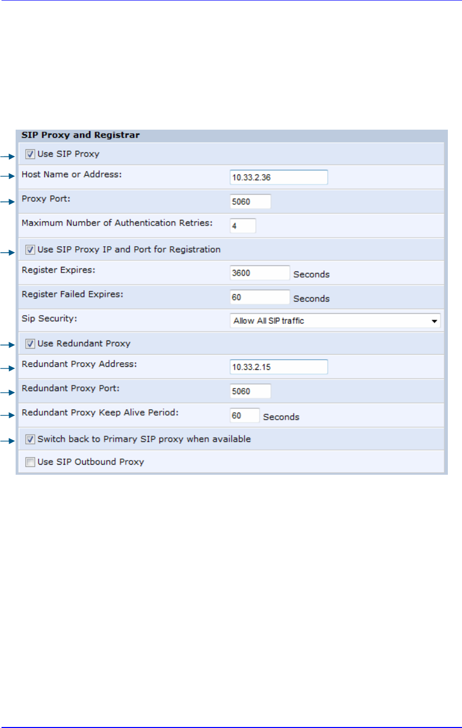
MP252 Multimedia Home Gateway 8. Configuring VoIP Parameters
Version 3.4.0 85 June 2011
d. In the 'Redundant Proxy Keep Alive Period' field, enter the rate (in seconds) of the
keep-alive messages for sending to the proxy. The valid range is 10 to 86,400
seconds (i.e., 24 hours). The default value is 60 sec.
e. To toggle between Symmetric and Asymmetric modes, use the 'Switch back to
Primary SIP proxy when available' check box.
♦
Asymmetric mode - select the check box (i.e., mark it)
♦
Symmetric mode - clear the check box
Figure 8-2: Configuring Proxy Redundancy
4. Click OK to save your settings.
2-a
3-a
2
-
b
2-c
3-a
3
-
b
3-c
3
-
d
3-e
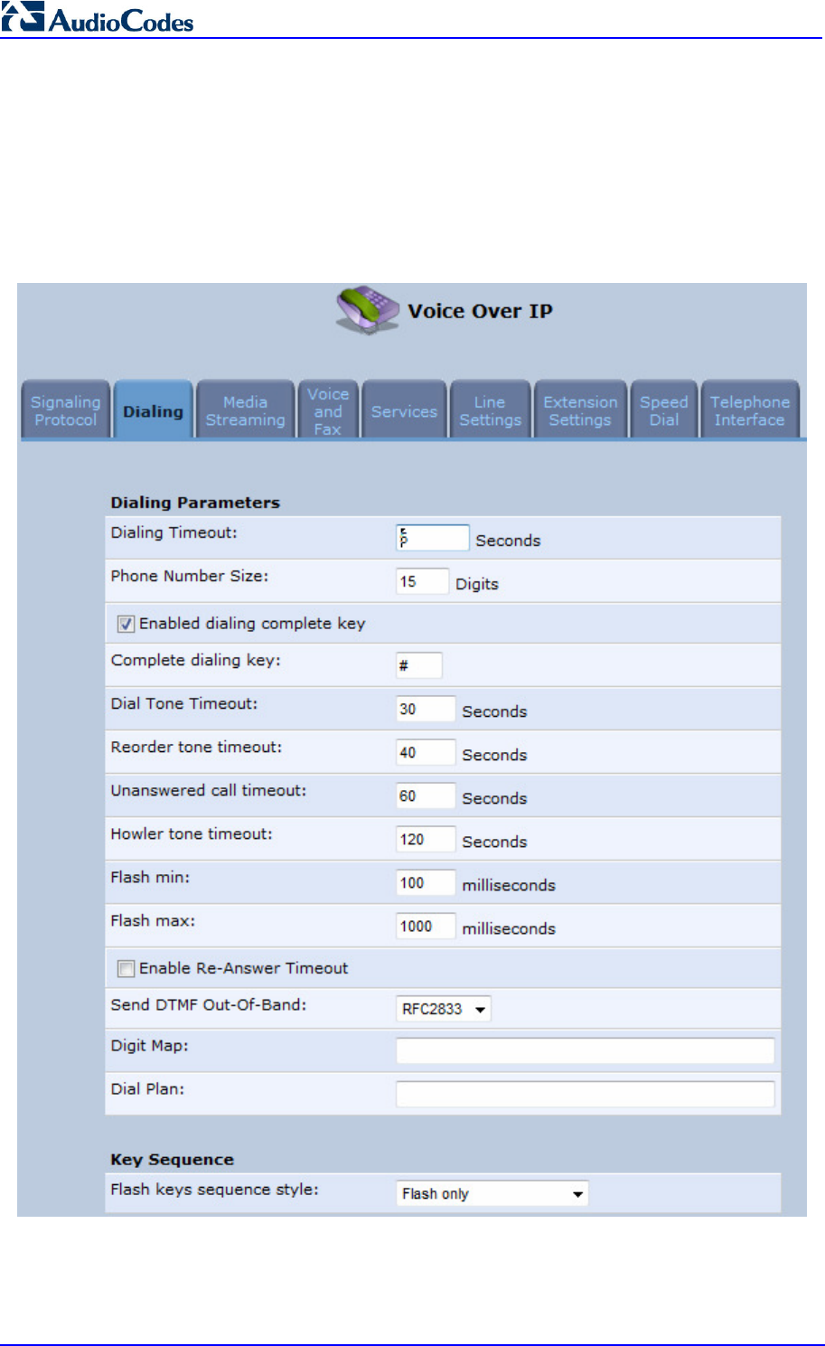
MP252 Multimedia Home Gateway 86 Document #: LTRT-23504
User's Manual
8.2 Configuring Dialing Parameters
The procedure below describes how to configure the dialing parameters.
To configure dialing parameters:
1. In the 'Voice Over IP' screen, click the Dialing tab; the following screen appears.
Figure 8-3: Dialing Tab Screen
2. Configure the parameters, as required. For a description of the parameters displayed on
this screen, see Table 8-2.
3. Click OK to save your settings.

MP252 Multimedia Home Gateway 8. Configuring VoIP Parameters
Version 3.4.0 87 June 2011
Table 8-2: Dialing Tab Parameters Description
Parameter Description
Dialing Parameters
Dialing Timeout
Defines the duration (in seconds) of allowed inactivity between dialed digits.
When you work with a proxy, the number you have dialed before the dialing
process has
timed out is sent to the proxy as the user ID to be called. This is
useful for calling remote parties without creating a speed dial entry
(assuming the remote party is registered with the proxy).
Phone Number Size Defines the maximum length of shortcu
t numbers that you can enter and the
maximum number of digits that you can dial.
Enabled dialing
complete key
When selected (default), you can define a key that when pressed forces
MP252 to make a call to the dialed digits even if there is no match in the
dial
plan or digit map. The key is defined in the ‘Complete dialing key’ field, which
appears when this parameter is selected.
Note: This parameter appears only in 'Advanced' mode.
Complete dialing key Defines the key that when pressed forces MP252 to m
ake a call to the dialed
digits even if there is no match in the dial plan or digit map. The default value
is the pound (#) key.
Note:
This parameter is available only if the ‘Enabled dialing complete key’ is
selected.
Dial Tone Timeout Defines the
duration of the dial tone (in seconds). If the limit is exceeded, the
dial tone stops and you a reorder tone is played.
Reorder Tone Timeout
Defines the duration (in seconds) of the reorder tone. The reorder tone is
played, for example, when MP252
receives a SIP 486 response. If the limit is
exceeded, the reorder tone stops and a howler tone is played.
Note: This parameter appears only in 'Advanced' mode.
Unanswered call
timeout
Defines the timeout before MP252 automatically sends a SIP CANCEL
message. When MP252 makes a call and the other side doesn’t answer,
MP252 sends a CANCEL message after this timeout.
Note: This parameter appears only in 'Advanced' mode.
Howler Tone Timeout Defines the duration (in seconds) of the howler
tone. If the limit is exceeded,
the howler tone stops playing. The howler tone informs a user that the user's
phone has been left in an off-hook state.
Note: This parameter appears only in 'Advanced' mode.
Flash min Defines the duration (in ms) after which you can begin to perform a flash
hook.
Flash max Defines the maximum duration (in ms) that the flash hook button can be
pressed, after which the call is disconnected.
Enable Re-Answer
Timeout
When selected, the ‘Re-Answer Timeout’ field appears, allowing you to
define the timeout after on-hooking an active call and then off-hooking it
again. Once this time expires and the phone has not been off-
hooked again,
the call is disconnected.
Send DTMF Out-Of-
Band
Defines how the DTMF tones are sent (‘Inband’, ‘RFC2833’, or ‘Via SIP’).
DTMFs are the tones generated by your telephone's keypad.
Note: This parameter appears only in 'Advanced' mode.

MP252 Multimedia Home Gateway 88 Document #: LTRT-23504
User's Manual
Parameter Description
Digit Map Defines formats (or patterns) for the dialed number. A match to one of the
defined patterns terminates the dialed number. For an explanation on digit
map syntax, see Section 8.2.1 on page 88.
Note: This parameter appears only in 'Advanced' mode.
Dial Plan Defines patterns to translate to specific SIP destination addresses. For dial
plan syntax rules for patterns entered to the left of the '=' sign, see Section
8.2.1 on page 88.
Note: This parameter appears only in 'Advanced' mode.
Key Sequence
Flash keys sequence
style
Defines the key sequence with the flash button:
‘Flash only’ (default) = uses only the phone's Flash button. There are
three scenarios:
During an existing call, if the user presses Flash, the call is put on
hold, a dial tone is heard and the user is able to initiate a second call.
Once the second call is established, on-hooking transfers the first
(held) call to the second call.
During an existing call, if the user presses Flash, the call is put on
hold and a dial tone is heard. The user can initiate a second call and
establish a 3-way conference by again pressing Flash after the
second call is initiated.
During an existing call, if a cal
l comes in (call waiting), pressing Flash
puts the active call on hold and answers the waiting call; pressing
Flash again toggles between these two calls.
‘Flash + digits sequence’ = Flash button with a key sequence:
Flash + 1 holds a call or toggles between two existing calls.
Flash + 2 makes a call transfer.
Flash + 3 establishes a 3-way conference.
'Send Flash Hook Via SIP' = you can modify the SIP INFO message that
is sent upon Flash. You can change the Content Type header field and
Message Body field.
Note: This parameter appears only in 'Advanced' mode.
SIP INFO Header
When the key sequence is set to 'Send Flash Hook Via SIP', you can modify
the Content Type header field of the SIP INFO message.
For example: "application/broadsoft; version = 1.0"
Note: This parameter appears only when the ‘Flash keys sequence style’
field is set to 'Send Flash Hook Via SIP'.
SIP INFO Body
When the key sequence is set to 'Send Flash Hook Via SIP', you can modify
the Message Body field of the SIP INFO message.
For example: " event flashhook"
Note: This parameter appears only when the ‘Flash keys sequence style’
field is set to 'Send Flash Hook Via SIP'.
8.2.1 Syntax for Digit Maps and Dial Plans
Digit maps and dial plans are defined using special syntax rules, configured in the 'Dialing'
screen (see Section 8.2 on page 85).
Digit Maps: A phone's digit map allows MP252 to know when an entered telephone
number is complete and therefore, when it should initiate the call. If the phone digit map
is defined incorrectly, MP252 might start to dial before the telephone user has entered

MP252 Multimedia Home Gateway 8. Configuring VoIP Parameters
Version 3.4.0 89 June 2011
all the required digits. A digit map is defined either by a (case insensitive) "string" or by a
list of strings. Each string in the list is an alternative numbering scheme, specified either
as a set of digits or as an expression over which MP252 attempts to find a shortest
possible match. The syntax that can be used in each numbering scheme is described in
the table below.
Dial Plans: A dial plan translates specific patterns into specific SIP destination
addresses. For example, dial plan rule "4xxx=Line_\\\@10.1.2.3" sends a dialed
number consisting of the digit “4” followed by any three digits to IP address 10.1.2.3.
The syntax of the pattern on the left of the '=' sign is described in the table below.
Table 8-3: Dial Plan (for Left of '=' Sign) and Digit Map Syntax
Type Syntax
Digit A digit from "0" to "9".
DTMF A digit, or one of the symbols "A", "B", "C", "D", "#", or "*". Extensions may be
defined.
Wildcard The symbol "x" which denotes any digit ("0" to "9").
Range One or more DTMF symbols enclosed between square brackets ("[" and "]").
Sub-range Two digits separated by a hyphen ("-") which matches any digit between and
including the two. The subrange can only be used inside a range construct, i.e.,
between "[" and "]".
Position
A period (".") which matches an arbitrary number, including zero, of occurrences of
the preceding construct.
For example:
[2-9]11|0|100|101|011xxx.|9011xxx.|1[2-9]xxxxxxxxx|91[2-9]xxxxxxxxx|9[2-9]xxxxxx|*xx|[8]x
xxx|[2-7]xxx
[2-9]11: 911 rule: 211, 311, 411, 511, 611, 711, 811, 911 are dialled immediately
0: Local operator rule
100: Auto-attendant default extension
101: Voicemail default extension
011xxx.: International rule without prefix
9011xxx.: International rule with prefix
1[2-9]xxxxxxxxx: LD rule without prefix
91[2-9]xxxxxxxxx: LD rule with prefix
9[2-9]xxxxxx: Local call with prefix
*xx: 2-digit star codes
[1-7]xx: A regular 3-digit extension that does not start with 9 or 8 is dialed immediately
[2-7]xx: A regular 3-digit extension that does not start with 9, 8, or 1 is dialed
immediately
[2-7]xxx: A regular 4-digit extension that does not start with 9, 8, or 1 is dialed
immediately
[8]xxx: A 3-digit extension prefixed with an 8 (routes calls directly to voicemail of
extension xxx)
[8]xxxx: A-4 digit extension prefixed with an 8 (routes calls directly to voicemail of
extension xxxx)
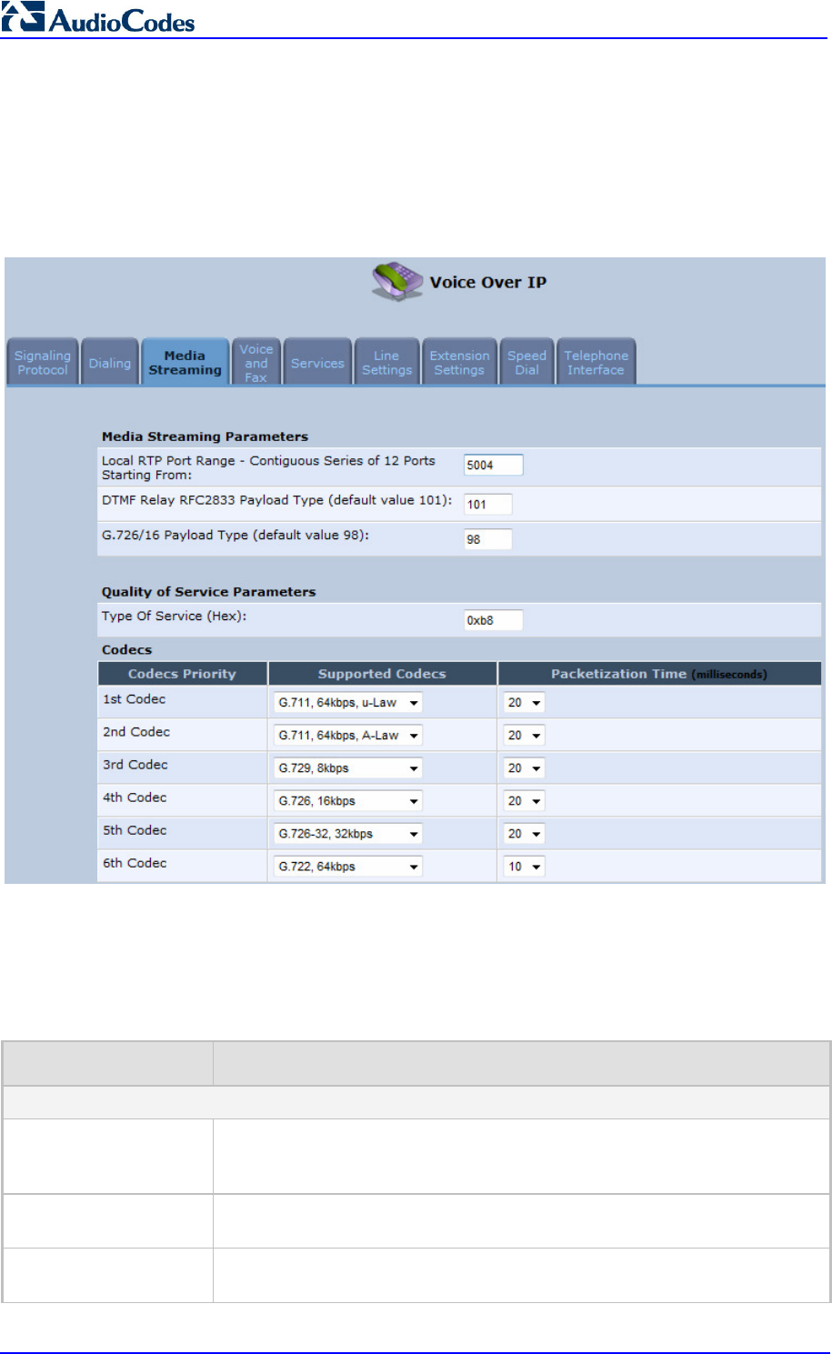
MP252 Multimedia Home Gateway 90 Document #: LTRT-23504
User's Manual
8.3 Configuring Media Streaming
The procedure below describes how to configure the media streaming parameters.
To configure media streaming parameters:
In the 'Voice Over IP' screen, click the Media Streaming tab; following screen appears.
Figure 8-4: Media Streaming Tab Screen
4. Configure the parameters, as required. For a description of the parameters displayed on
this screen, see Table 8-4.
5. Click OK to save your settings.
Table 8-4: Media Streaming Tab Parameters Description
Parameter Description
Media Streaming Parameters
Local RTP Port Range -
Contiguous Series of 8
Ports Starting From:
Defines the port range for Real Time Protocol (RTP) voice transport.
DTMF Relay RFC 2833
Payload Type
Defines the RTP payload type used for RFC 2833 DTMF relay packets. The
range is 0-255. The default is 101.
G.726/16 Payload Type
Defines the RTP payload type used for 16 kbps G.726 packets. The range is
0-255. The default is 98.

MP252 Multimedia Home Gateway 8. Configuring VoIP Parameters
Version 3.4.0 91 June 2011
Parameter Description
Quality of Service Parameters
Type of Service (Hex) This is a part of the IP header that defines the type of routing service to be
used to tag outgoing voice packets originated from MP252. It is used to
inform routers along the way that this packet should get specific QoS. Leave
this value as 0xb8 (default) if you are unfamiliar with the Differentiated
Services IP protocol parameter.
Codecs
1
st
- 6
th
Codec Defines the voice codec. For more information, see 8.3.1 on page 91.
8.3.1 Configuring Codecs
Codecs define the method of relaying voice data. Different codecs have different
characteristics, such as data compression and voice quality. For example, G.723 is a codec
that uses compression, so it is good for use where bandwidth is limited but its voice quality is
not as good compared to other codecs such as the G.711.
8.3.1.1 Supported Codecs
To make a call, at least one codec must be enabled. Moreover, all codecs may be enabled
for best performance. When you start a call to a remote party, your available codecs are
compared against the remote party's to determine the codec used. The priority by which the
codecs are compared is according to their order of appearance in the table (descending
order). To change the priorities, rearrange the codecs in the required order.
If there is no codec that both parties have made available, the call attempt fails. Note that if
more than one codec is common to both parties, you cannot force which of the common
codecs that were found are used by the remote party's client. If you do wish to force the use
of a specific codec, leave only that codec checked.
8.3.1.2 Packetization Time
The Packetization Time is the length of the digital voice segment that each packet holds. The
default is 20 millisecond packets. Selecting 10 millisecond packets reduces the delay but
increases the bandwidth consumption.
8.4 Configuring Voice and Fax
The procedure below describes how to configure the voice and fax parameters.
To configure voice and fax parameters:
1. In the 'Voice Over IP' screen, click the Voice and Fax tab; the following screen appears.
Figure 8-5: Voice and Fax Tab Screen

MP252 Multimedia Home Gateway 92 Document #: LTRT-23504
User's Manual
2. Configure the parameters, as required. For a description of the parameters displayed on
this screen, see Table 8-5.
3. Click OK to save your settings.

MP252 Multimedia Home Gateway 8. Configuring VoIP Parameters
Version 3.4.0 93 June 2011
Table 8-5: Voice and Fax Tab Parameters Description
Parameter Description
Gain Control
Enable Automatic Gain
Control
Enables the Automatic Gain Control (AGC) mechanism. The AGC
mechanism adjusts the level of the received signal to maintain a steady
(configurable) volume level.
Automatic Gain Control
Direction
Defines the AGC direction (local or remote user).
Note: This parameter appears only if the ‘Enable Automatic Gain Control’
check box is selected.
Target Energy Defines the signal energy value (in dBm) that the AGC attempts to attain.
The range is 0 to -63 dBm. The default value is -19 dBm.
Note: This parameter appears only if the ‘Enable Automatic Gain Control’
check box is selected.
Jitter Buffer
Minimum Delay
Defines the initial and minimal delay of the adaptive jitter buffer mechanism,
which compensates for network problems. The value should be set
according to the expect
ed average jitter in the network (in milliseconds). The
default is 35 msec.
Optimization Factor Defines the adaptation rate of the jitter buffer mechanism. Higher values
cause the jitter buffer to respond faster to increased network jitter. The
default is 7.
Silence Compression
Enable Silence
Compression
Enables silence compression, which reduces the network bandwidth
consumption. The default is disabled.
Enable G.711/G.726
Comfort Noise
Enables the Comfort Noise generation feature. When enabled
and silence is
detected, MP252 transmits a series of parameters called Silence Information
Descriptor (SID), which are used to reproduce the local background noise at
the remote (receiving) side.
Note: This parameter appears only if the ‘Enable Silence Compression’
check box is selected.
Echo Cancellation
Enable Echo
Cancellation
Enables (default) echo cancellation (disabling echo cancellation should be
done for testing purposes only).
Fax and Modem Settings
Fax Transport Mode Selects the way fax calls are handled:
Transparent = Fax is transferred in-band (like a voice call) - can be
used if the codec is G.711
T.38 Relay = Fax is relayed to the remote side according to the T.38
standard
Voice Band Data = Switch to G.711 via SIP messaging
Bypass = An automatic switch to AudioCodes' proprietary payload
type (102, 103).
Max Rate Defines the maximum fax rate.
2.4 Kbps, 4.8 Kbps, 7.2 Kbps, 9.6 Kbps, 12 Kbps or 14.4 Kbps (default).
Note: This parameter appears only if 'Fax Transport Mode' is set to ‘T.38
Relay’.

MP252 Multimedia Home Gateway 94 Document #: LTRT-23504
User's Manual
Parameter Description
Max Buffer Defines the maximum amount of T.38 data stored on the MP252. The valid
range is 128 to 2048. The default is 1024.
Note: This parameter appears only if 'Fax Transport Mode' is set to ‘T.38
Relay’.
Max Datagram
Defines the maximum total size of TCP/UDPTL packets that can be received
at the remote gateway. The valid range is 160 to 1020. The default is 320.
Note: This parameter appears only if 'Fax Transport Mode' is set to ‘T.38
Relay’.
Image Data
Redundancy Level
Defines the level for output Image Data (2400…14400 bps).
0 = No redundancy
1 to 3 = Redundancy level
Note: This parameter appears only if 'Fax Transport Mode' is set to ‘T.38
Relay’.
T30 Control Data
Redundancy Level
Defines the redundancy level for output T.30 Control Data (300 bps).
0 = No redundancy
1 to 7 = Redundancy level
Note: This parameter appears only if 'Fax Transport Mode' is set to ‘T.38
Relay’.
Fax Relay Jitter Buffer
Delay
Defines the Fax Relay Jitter Buffer.
0 = Adaptive Jitter Buffer. The MP252 sets the Jitter Buffer size
automatically and then adapts it according to network conditions.
1 to 511 = Fixed Jitter Buffer size (in msec).
Note: This parameter appears only if 'Fax Transport Mode' is set to ‘T.38
Relay’.
Error Correction Mode
Enables (default) fax error correction mode (ECM).
Note: This parameter appears only if 'Fax Transport Mode' is set to ‘T.38
Relay’.
Fax Bypass Payload
Type
Defines the payload type for fax in Bypass mode.
Note: This parameter appears only if 'Fax Transport Mode' is set to ‘Bypass’.
Modem Transport Mode Selects the way modem calls are handled:
Transparent = Data is transferred in-
band (like a voice call). This can be
used if the codec is G.711.
Voice Band Data = Switch to G.711 via SIP messaging.
Bypass = An automatic switch to AudioCodes' proprietary payload type
(102, 103).
Note:
If the Fax transport mode is Bypass or VBD, it must match the Modem
transport mode.
Modem Bypass
Payload Type
Defines the payload type for modems in Bypass mode.
Note: This parameter appears only if 'Modem Transport Mode' is set
‘Bypass’.
Fax/Modem Bypass
Codec
Defines the codec for the VBD and Bypass modes. PCMA (default) or
PCMU.
G.711 64 kbps A-Law
-OR-
G.711 64 kbps u-Law

MP252 Multimedia Home Gateway 8. Configuring VoIP Parameters
Version 3.4.0 95 June 2011
Parameter Description
CED Transfer Mode
By Fax Relay: When MP252 is the receiver side, Switch to Fax relay is
enabled upon CED. This allows a high reliable fax-over-IP call
establishment at the beginning of CED tone.
In Voice Or PCM Bypass: When MP252 is the receiver side, to avoid
possible conflicts with low-
speed modems, the CED (ANS) relay by FoIP
protocol may be disabled by setting the CED transfer mode to ‘In Voice
Or PCM Bypass’. In this case, MP252 does not initiate the Fax Relay on
detecting CED tone in absence of CNG, but switches to VBD or remains
in voice mode (depends on the Modem Transport Mode). MP252
switches to
FoIP later when it defines exactly that a monitored call is the
fax call (CED and CND or V.21 Preamble).
Enable CNG Detection
Enables detection of the fax CNG signal. When the local fax machine
connected to MP252 receives a fax, MP252
switches to T.38 fax relay upon
detection of the CED signal from the remote fax. If the local fax machine
sends a fax, MP252 switches to T.38 only after detecting the CNG signal
from the local side and the CED signal from the remote side. If this check bo
x
is selected, MP252 switches to T.38 relay immediately upon detection of the
CNG signal from the local side, without waiting for the CED signal from the
remote side. The default is disabled.
Switch To Fax Only By
The Answering Side
Typically, switching to fax mode is the responsibility of the answering side.
However, in some cases, the sending machine can also switch to fax mode.
If this check box is marked, the sending machine does not switch to fax, but
allows the answering side to detect the fax and switch to fax mode.
8.5 Configuring Supplementary Services
The procedure below describes how to configure the services parameters.
To configure supplementary services:
1. In the 'Voice Over IP' screen, click the Services tab; the following screen appears.
Figure 8-6: Services Tab Screen
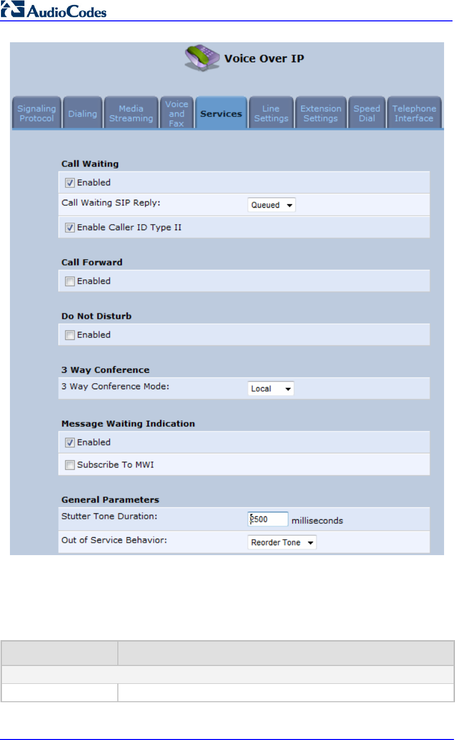
MP252 Multimedia Home Gateway 96 Document #: LTRT-23504
User's Manual
2. Configure the parameters, as required. For a description of the parameters displayed on
this screen, see Table 8-6.
3. Click OK to save your settings.
Table 8-6: Services Tab Parameters Description
Parameter Description
Call Waiting
Enabled Enables the Call Waiting feature.

MP252 Multimedia Home Gateway 8. Configuring VoIP Parameters
Version 3.4.0 97 June 2011
Parameter Description
Call Waiting SIP Reply
Defines the SIP response (180 Ringing or 182 Queued -
default) sent when
another call arrives while a call is in progress.
Note: This parameter appears only if Call Waiting is enabled.
Enable Caller ID Type II
Enables caller ID of a waiting call (Called Caller ID type 2).
Note: This parameter appears only if Call Waiting is enabled.
Call Forward
Enabled
Enables call forwarding. The Call Forward feature permits a user to redirect
incoming calls addressed to another number. The user’s ability to originate
calls is unaffected by Call Forward.
Note: The Call Forward feature is functional only when MP252 is re
gistered
to a proxy.
Call Forward Type Defines the type of call forwarding:
Unconditional:
Incoming calls are forwarded independently of the status
of the endpoint.
Busy: Incom
ing calls are forwarded only if the endpoint is busy, i.e., if all
lines are active.
No Reply: Incoming calls are forwarded only if the endpoint does not
answer before a user-defined timeout (see ‘Time for No Reply Forward’
parameter).
Note: This parameter appears only if Call Forward is enabled.
Time for No Reply
Forward
Defines the timeout after which the call is forwarded if the endpoint does not
answer. If you specify 5 seconds, for example, and 'No Reply' is selected for
parameter 'Call Forward Type' (see above), incoming calls are forwarded
only after 5 seconds lapse.
Note: This parameter is available only when ‘No Reply’ is selected for the
parameter 'Call Forward Type'.
Key Sequence
The default is *72 but users can modify to any sequence of up to 2 digits, i.e.,
*n or *nm.
Do Not Disturb
Enabled Enables the Do Not Disturb (DND) feature. This feature allows you to
prevent incoming calls from ringing at your phone. When enabled, callers
receive a busy signal or an announcement. The DND is activated using the
phone keypad. The default is disabled.
Key Sequence Defines the key sequence to activate and deactivate the DND feature.
3 Way Conference
3 Way Conference
Mode
Selects how 3-way conference calls are handled:
Local: locally by MP252
Remote: by a remote media server (RFC 4240)
Media Server Address
The address of the remote media server that handles conference calls.
Note: This parameter is available only when ‘Remote’ is selected for the
parameter '3 Way Conference Mode'.

MP252 Multimedia Home Gateway 98 Document #: LTRT-23504
User's Manual
Parameter Description
Message Waiting Indication
Enabled If a user has an unheard voice mail message, a stutter dial tone is heard
when the user picks up the phone. In addition, MP252 generates an FSK
signal to the phone to indicate that a message is waiting. If the telephone
connected to MP252 supports this feature, an MWI ‘envelope icon’ is
displayed.
Subscribe to MWI
Select this check box if you must register with a MWI subscriber server. If so,
configure the three parameters below.
MWI Server IP Address
or Host Name
Defines the IP address or host name of the MWI server.
Note: This parameter is available only when the check box 'Subscribe to
MWI' is selected.
MWI Server Port Defines the port number of the MWI server.
Note: This parameter is available only when the check box 'Subscribe to
MWI' is selected.
MWI Subscribe
Expiration Time
Defines the interval between registrations.
Note: This parameter is available only when the check box 'Subscribe to
MWI' is selected.
General Parameters
Stutter Tone Duration
When you enable message waiting and an unheard message exists, a stutter
tone is played to the phone for the duration configured by this parameter
and/or when you activate the call forwarding feature (see Section 10.6 on
page 111).
Out of Service Behavior
Defines the tone which is p
layed instead of a dial tone if the user configured a
registrar IP and the registration failed. When the Reorder tone is selected, a
Reorder tone is played instead of a dial tone. If “No Tone” is selected, then no
tone is played.
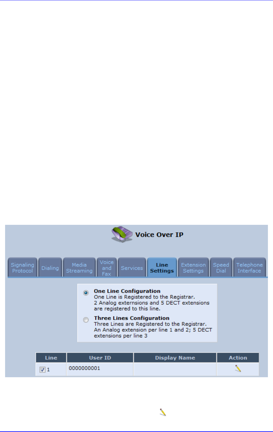
MP252 Multimedia Home Gateway 8. Configuring VoIP Parameters
Version 3.4.0 99 June 2011
8.6 Configuring Line Settings
Before you can make phone calls, you need to configure lines. Lines are SIP logical ID
numbers (i.e., telephone numbers), which are registered to the SIP proxy server, and for
which you are charged for calls you make on it.
MP252 supports two line-configuration modes:
One-Line Configuration: In this mode, only one line is configured to represent all the
physical telephone extensions on MP252 (i.e., two analog phones and five DECT
handsets):
• When you receive an incoming call, all the extensions on the line ring, and you can
answer from any one of them. When you do answer, the other extensions stop
ringing.
• If you receive another incoming call when you already have an established call on
one extension, all the idle extensions ring, and the busy extension hears a call
waiting tone.
• You can make outgoing calls from any of the extensions.
• You can make multiple concurrent calls (i.e., each extension makes a call to a
different destination and at the same time).
Three-Lines Configuration: In this mode, three lines can be configured:
• Line 1 for the analog telephone connected to the MP252 port labeled Phone 1
• Line 2 for the analog telephone connected to the MP252 port labeled Phone 2
• Line 3 for all the DECT handsets (up to five)
To configure lines:
1. In the 'Voice Over IP' screen, click the Line Settings tab; the following screen appears.
Figure 8-7: Line Settings Tab Screen
2. Select the configuration mode options – One Line Configuration or Three Lines
Configuration; the table lists the lines according to the selected line configuration
mode.
3. For each line, click the corresponding Edit icon to configure the line; the following
screen appears:
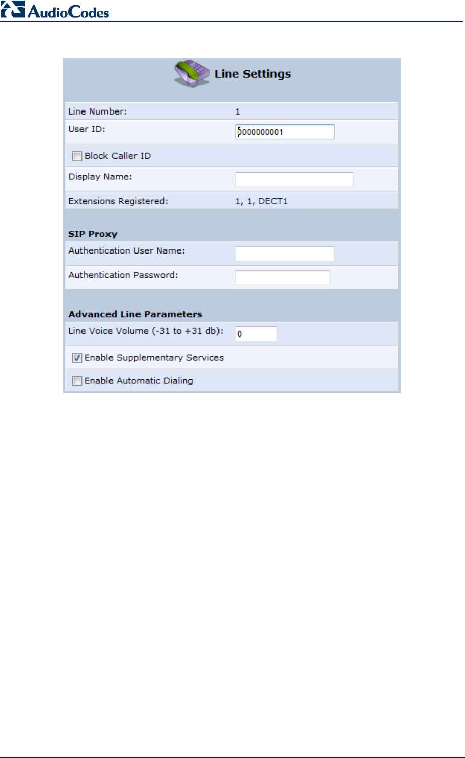
MP252 Multimedia Home Gateway 100 Document #: LTRT-23504
User's Manual
Figure 8-8: Line Settings Screen for a New Line
The screen displays the following read-only information:
• Line Number: line number
• Extensions Registered: extensions registered to this line
4. In the ‘User ID’ field, enter phone's VoIP user ID used for identification to initiate and
accept calls.
5. To hide the phone’s ID from the remote party, select the ‘Block Caller ID’ check box.
6. In the ‘Display Name’ field, enter a name to intuitively identify the line. This is also
displayed to remote parties as your caller ID.
7. Under the SIP Proxy group, define the SIP proxy server:
a. In the ‘Authentication User Name’ field, enter the user name received from your
VoIP service provider. This is used when sending a response to Unauthorized or
Proxy Authentication Requested (401/407).
b. In the ‘Authentication Password’ field, enter the password received from your VoIP
service provider. This is used when sending a response to Unauthorized or Proxy
Authentication Requested (401/407).
8. In the ‘Line Voice Volume’ field, enter the voice volume of the line (i.e., the gain from the
network toward the local phone). The default is 0 dB.
9. To enable supplementary services on this line, select the ‘Enable Supplementary
Services’ check box.
10. To enable automatic dialing (which automatically dials a user-defined phone number
when the line is off-hooked longer than a user-defined time), do the following:
c. Select the ‘Enable Automatic Dialing’ check box.

MP252 Multimedia Home Gateway 8. Configuring VoIP Parameters
Version 3.4.0 101 June 2011
d. In the ‘Automatic Dialing Timeout’ field, enter the time after which automatic dialing
is activated if the user has not started dialing before this timeout. When set to 0,
automatic dialing is performed immediately.
e. In the ‘Automatic Dialing Destination’ field, enter the destination that is
automatically dialed. This can be a phone number or a domain name (for example,
user@101.10.13.2 or user@domain name).
11. Click OK to save your settings.
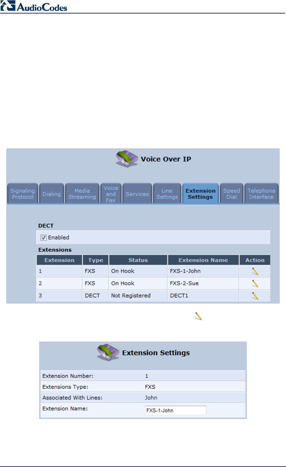
MP252 Multimedia Home Gateway 102 Document #: LTRT-23504
User's Manual
8.7 Configuring Line Extensions
Extensions are the physical telephony extensions on MP252. These can either be FXS ports
(for analog telephones) or cordless DECT handsets.
Once you have defined your lines, you can do the following:
Define an arbitrary name for each extension (to help you identify the extension).
Initiate the registration process of the lines with the proxy server (and DECT with base
unit)
To configure line extensions:
1. In the 'Voice Over IP' screen, click the Extension Settings tab; the following screen
appears.
Figure 8-9: Extension Settings Tab Screen
2. For each line extension, click the corresponding Edit icon to define a name for the
extension; the following screen appears:
Figure 8-10: Extension Settings Screen
3. Click OK to save your settings.
To register the lines:
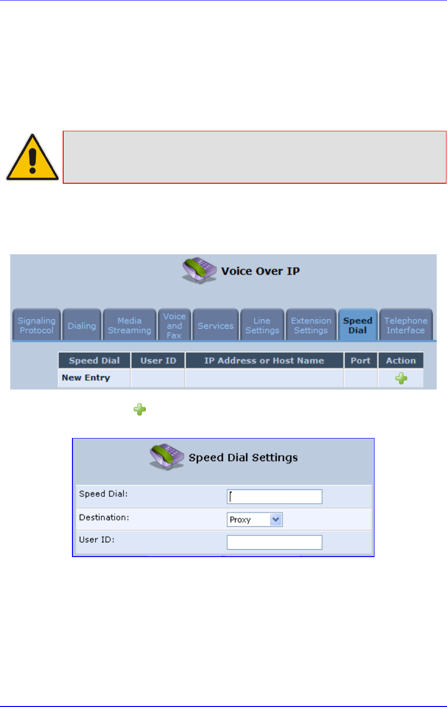
MP252 Multimedia Home Gateway 8. Configuring VoIP Parameters
Version 3.4.0 103 June 2011
4. In the ‘Extension Settings Tab; screen; click the Register button.
8.8 Configuring Speed Dialing
Use the 'Speed Dial Settings' screen to associate a called party's contact parameters
(including the IP address of his/her ATA and Line ID) with a number that you'll dial to call the
called part. The number of speed-dialing codes that can be defined is unlimited. Use the
screen to define a destination type: Proxy, Local Line or Direct Call.
Note: When connecting MP252 to a World-Wide SIP Server (see 'Connecting
MP252's VoIP to a VoIP Service Provider' on page 107), you don't need to
configure 'Speed Dial Settings'.
To configure speed dialing:
1. In the 'Voice Over IP' screen, click the Speed Dial tab; the following screen appears:
Figure 8-11: Speed Dial Tab Screen
2. Click the New icon; the 'Speed Dial Settings' screen appears.
Figure 8-12: Speed Dial Settings Screen (Proxy Destination)
3. In the ‘Speed Dial’ field, enter the shortcut number (i.e., speed dial) which you dial to call
the party defined below.
4. From the ‘Destination’ drop-down list, select the destination type.
• Proxy: If you select this option (as shown in the figure above), then in the ‘User ID’
field, enter the user ID to call.
• Local Line: If you select this option, then from the ‘Line’ drop-down list, select the
configured local line on your MP252.
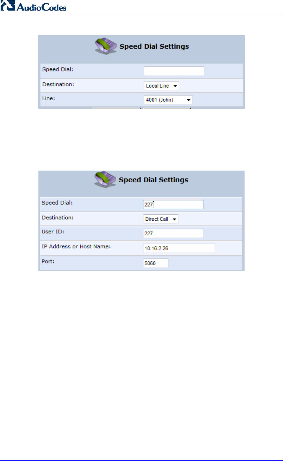
MP252 Multimedia Home Gateway 104 Document #: LTRT-23504
User's Manual
Figure 8-13: Speed Dial Settings Screen (Local Line Destination)
• Direct Call: if you select this option, then configure the following:
a. In the ‘User ID’ field, enter the user ID to call.
b. In the ‘IP Address or Host Name’ field, enter the remote party's IP address or
host name.
c. In the ‘Port’ field, enter the SIP UDP or TCP port of the remote party.
Figure 8-14: Speed Dial Settings Screen (Direct Call Destination)
5. Click OK to save your settings.
8.9 Enabling Polarity Reversal
The procedure below describes how to enable polarity reversal. When this feature is enabled,
the analog port (FXS) interface polarity is reversed to indicate the start of a VoIP session,
and is reversed back when the VoIP session ends.
To enable polarity reversal:
1. In the 'Voice Over IP' screen, click the Telephone Interface tab; the following screen
appears:
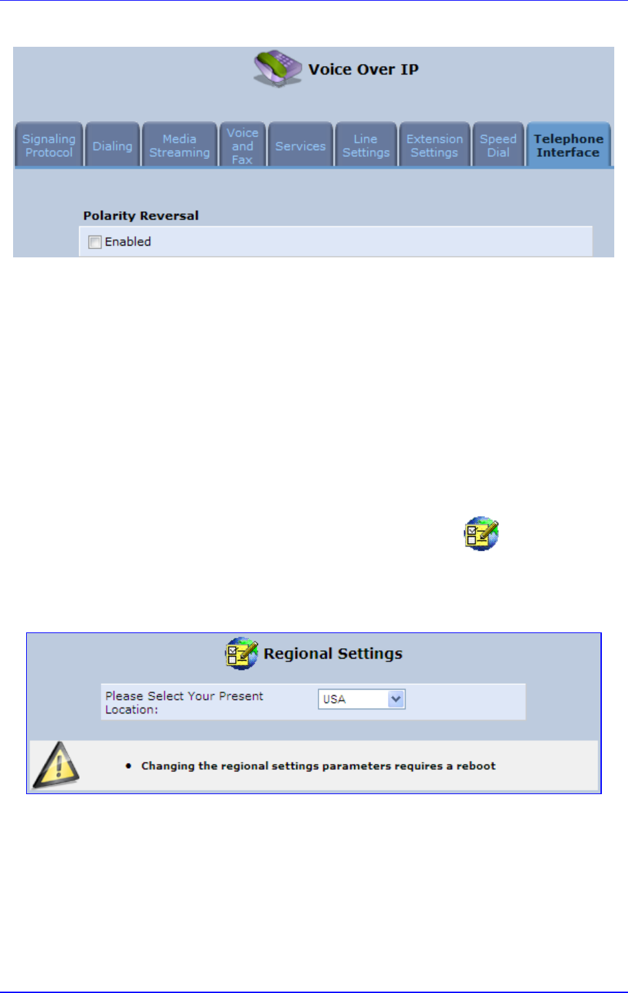
MP252 Multimedia Home Gateway 8. Configuring VoIP Parameters
Version 3.4.0 105 June 2011
Figure 8-15: Telephone Interface Tab Screen
2. Select the 'Enabled' check box to enable the Polarity Reversal feature.
3. Click OK to apply your settings.
8.10 Selecting Regional Settings for Analog Lines
The behavior and parameters of analog telephones lines vary between countries. The set of
Call Progress Tones, the protocol used for caller ID and the analog line impedance are all
location-specific. MP252 enables users to select the country they reside in and MP252
automatically selects the correct regional settings.
To select your present location:
1. In the 'Advanced' screen, click the Regional Settings icon; the 'Regional
Settings' screen appears.
2. Select the country from the drop-down list. If your current location is not listed, contact
your service provider.
Figure 8-16: Regional Settings Screen
3. Click OK.
4. Reboot MP252 for your settings to take effect.

MP252 Multimedia Home Gateway 106 Document #: LTRT-23504
User's Manual
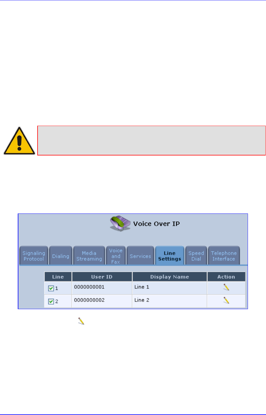
Version 3.4.0 107 July 2011
MP252 Multimedia Home Gateway 9. Connecting MP252 to an ITSP
9 Connecting MP252 to an ITSP
The MP252 VoIP capabilities allow you to connect to a remote SIP server or Internet
Telephony Service Provider (ITSP) and conduct phone calls over the Internet (i.e., VoIP).
This chapter describes how to place a VoIP call utilizing MP252's VoIP capabilities over a
SIP server. Verify that your MP252 and telephone are correctly connected and that your
WAN connection is up.
9.1 Opening a SIP Account
Before you can connect to a SIP server, it is necessary that you obtain a SIP account.
9.2 Configuring VoIP Parameters
Note: This section describes the minimal set of changes required to connect to a VoIP
Service Provider. Other configuration changes might be required to connect to
some Service Providers.
To configure VoIP parameters:
1. In the menu bar, click the menu Voice Over IP; the ‘Voice Over IP’ screen appears.
2. Click the Line Settings tab. Enable only the lines that you are using, by selecting the
check box, and then click Apply.
Figure 9-1: Voice Over IP - Line Settings Screen
3. Click the Edit icon corresponding to the line that you want to configure (example, line
1); the ‘Line Settings’ screen appears. Use the configuration values provided by your
ISP to configure the parameters in this screen.
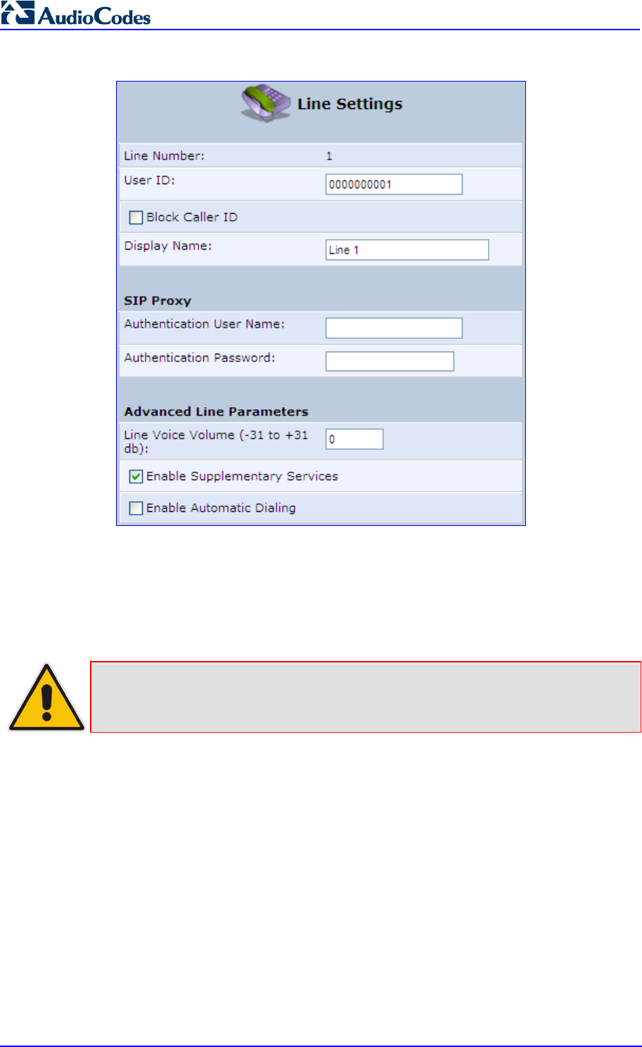
MP252 Multimedia Home Gateway 108 Document #: LTRT-23504
User's Manual
Figure 9-2: VoIP - Line Settings - Defining a New Line
4. Click the Signaling Protocol tab and then select the ‘Use SIP Proxy’ check box (see
'Configuring Signaling Protocol Parameters' on page 77).
5. In the field ‘Proxy IP Address or Host Name’, define the ISP’s SIP proxy, provided by the
ISP (see 'Configuring Signaling Protocol Parameters' on page 77).
6. Click OK or Apply to complete the VoIP configuration.
Note: To verify successful registration with the proxy server, ensure that the Phone
LED is lit green or in the Voice over IP tab (System Monitoring menu), the
entry ‘SIP Registration’ displays “Registered” for the configured lines.

Version 3.4.0 109 July 2011
MP252 Multimedia Home Gateway 10. Making VoIP Calls with your Analog Telephones
10 Making VoIP Calls with your Analog
Telephones
Analog telephone users that are connected to MP252 can place calls, put calls on hold,
transfer calls, and establish three-way conferences. This chapter describes how to perform
these operations.
Note: For information on using the DECT phone, see Part II.
10.1 Making a Call
The procedure below describes how to make a call.
To make a call:
1. Pick up the phone.
2. Make sure that you can hear a dial tone
3. Dial the remote party's number or the user-defined speed dial number (if configured in
Section 8.8 on page 103).
10.2 Answering a Waiting Call
The procedure below describes how to answer a waiting call. This depends on how you
configured the flash-hook functionality, using the ‘Flash keys sequence style’ parameter in
Section 8.2 on page 86. To enable call waiting, see Section 8.5 on page 95.
To answer a waiting call when 'Flash only' is set:
1. When you hear a call waiting tone (during a call), press the flash key button on your
phone; the active call is put on hold and switches to the waiting call.
2. To return to the original call, press the flash button again. You can toggle from one party
to another by pressing the flash button.
To answer a waiting call when 'Flash + digits sequence' is set:
1. When you hear the call waiting tone (during a call), press the flash key button on your
phone and then press the '1' key; the original call is put on hold and switches to the
waiting call.
2. To return to the original call, press flash + 1 again. You can toggle from one party to
another by pressing flash + 1.

MP252 Multimedia Home Gateway 110 Document #: LTRT-23504
User's Manual
10.3 Placing a Call on Hold
The procedure below describes how to place a call on hold. This depends on how you
configured the flash-hook functionality, using the ‘Flash keys sequence style’ parameter in
Section 8.2 on page 86.
To place the remote party on hold when 'Flash only' is set:
During a call, press the flash key button on your phone; a dial tone is heard. At this point
you can initiate a second call by dialing another party's number.
Note: If you press the flash key button again before the second party answers, the
call is established with the original call. If, however, the second party answers
and you press the flash key button, a 3-way conference is established.
To place the remote party on hold when 'Flash + digits sequence' is set:
1. Press the flash key button key and then press the '1' key on your phone; the phone plays
a dial tone. At this point you can initiate a second call by dialing another party's number.
2. To cancel the hold state and resume the previous phone call, press the flash key button
and then press '1'.
10.4 Transferring a Call
The procedure below describes how to transfer an established call to another destination.
This depends on how you configured the flash-hook functionality, using the ‘Flash keys
sequence style’ parameter in Section 8.2 on page 86.
To transfer a call when 'Flash only' is set:
1. During a call with party B, press the flash key button on your phone; party B is placed on
hold and a dial tone is heard.
2. Dial party C's number.
3. You can wait for C to answer or not.
4. On-hook your phone; party B is now transferred to party C.
To transfer a call when 'Flash + digits sequence' is set:
1. During a call with party B, press the flash key button and then press the '1' key on the
phone; party B is placed on hold and a dial tone is heard.
2. Dial party C's number.
3. You can wait for C to answer or not.
4. Press the flash key button key and then press '2'; party B is transferred to party C (and a
warning tone is heard).

MP252 Multimedia Home Gateway 10. Making VoIP Calls with your Analog Telephones
Version 3.4.0 111 June 2011
10.5 Establishing a 3-Way Conference Call
The procedure below describes how to establish a 3-way conference call. The method for
doing this depends on how you configured the flash-hook functionality, using the ‘Flash keys
sequence style’ parameter in Section 8.2 on page 86. In addition, to configure 3-way
conferencing, see Section 8.5 on page 95.
To establish a 3-way conference call when 'Flash only' is set:
1. During a call with party B, press the flash key button on your phone; Party B is placed on
hold and a dial tone is heard.
2. Dial party C's number and wait until the call is established.
3. Press the flash key button again to add parties B and C to a 3-way conference call.
4. To end the 3-way conference call, on-hook your phone (or alternatively, press the flash
key button again).
To establish a 3-way conference call when 'Flash + digits sequence' is
set:
1. During a call with party B, press the flash key button on your phone and then press the
'1' key; Party B is placed on hold and a dial tone is heard.
2. Dial party C's number and wait until the call is established.
3. Press the flash key button and then press the '3' key to add B and C to a 3-way
conference call.
4. To end the 3-way conference call, on-hook your phone (or alternatively, press the flash
key button and then press the '3' key).

MP252 Multimedia Home Gateway 112 Document #: LTRT-23504
User's Manual
10.6 Forwarding Calls to another Phone
The procedure below describes how to automatically forward incoming (received) calls to
another phone. Before you can forward calls, you need to enable and configure call
forwarding as described in Section 8.5 on page 95.
Note: The Call Forward feature is functional only when MP252 is registered to a proxy.
To forward calls to another phone:
1. Pick up the phone and make sure that you can hear a dial tone.
2. Dial the call forward key sequence (according to your configuration), for example, *32; a
dial tone is heard.
3. Dial the number of the phone to where you want calls forwarded; a stutter tone is heard.
4. Replace the receiver; all incoming calls are forwarded. Every time you pick up the
phone receiver, a stutter tone is played (for the length of time, as you configured for the
'Stutter Tone Duration' parameter).
To deactivate call forwarding:
1. Pick up the phone; a stutter tone is heard.
2. Dial the call forward key sequence.
3. Replace the receiver.
4. To make sure that call forwarding has been de-activated, pick up the phone again; a
regular dial tone should be heard (not the stutter tone).

Version 3.4.0 113 July 2011
MP252 Multimedia Home Gateway 11. Quality of Service
11 Quality of Service
Network-based applications and traffic are growing at a high rate, producing an
ever-increasing demand for bandwidth and network capacity. For obvious reasons,
bandwidth and capacity cannot be expanded infinitely, requiring that bandwidth-demanding
services be delivered over existing infrastructure, without incurring additional, expansive
investments.
The next logical means of ensuring optimal use of existing resources are Quality of Service
(QoS) mechanisms for congestion management and avoidance. QoS refers to the capability
of a network device to provide better service to selected network traffic. This is achieved by
shaping the traffic and processing higher priority traffic before lower priority traffic.
As QoS is dependent on the "weakest link in the chain", failure of but a single component
along the data path to assure priority packet transmission can easily cause a VoIP call or a
Video on Demand (VoD) broadcast to fail miserably. QoS must therefore obviously be
addressed end-to-end.
The following are the potential bottleneck areas that need be taken into consideration when
implementing an end-to-end QoS-enabled service.
The Local Area Network: LANs have finite bandwidth, and are typically limited to 100
Mbps. When given the chance, some applications consume all available network
bandwidth. In business networks, a large number of network-attached devices can lead
to congestion. The need for QoS mechanisms is more apparent in wireless LANs,
where bandwidth is even more limited (typically no more than 20 Mbps on 802.11g
networks).
The Broadband Router: All network traffic passes through and is processed by the
broadband router. It is therefore a natural focal point for QoS implementation. Lack of
sufficient buffer space, memory or processing power, and poor integration among
system components can result in highly undesirable real-time service performance. The
only way to assure high QoS is the use of proper and tightly-integrated router operating
system software and applications, which can effectively handle multiple real-time
services simultaneously.
The Broadband Connection: Typically, the most significant bottleneck of the network,
this is where the high speed LAN meets limited broadband bandwidth. Special QoS
mechanisms must be built into routers to ensure that this sudden drop in connectivity
speed is taken into account when prioritizing and transmitting real-time service-related
data packets.
The Internet: Internet routers typically have a limited amount of memory and bandwidth
available to them, so that congestions may easily occur when links are over-utilized,
and routers attempt to queue packets and schedule them for retransmission. One must
also consider the fact that while Internet backbone routers take some prioritization into
account when making routing decisions, all data packets are treated equally under
congested conditions.
Note: For recommended QoS configuration see Section 11.7 on page 128.
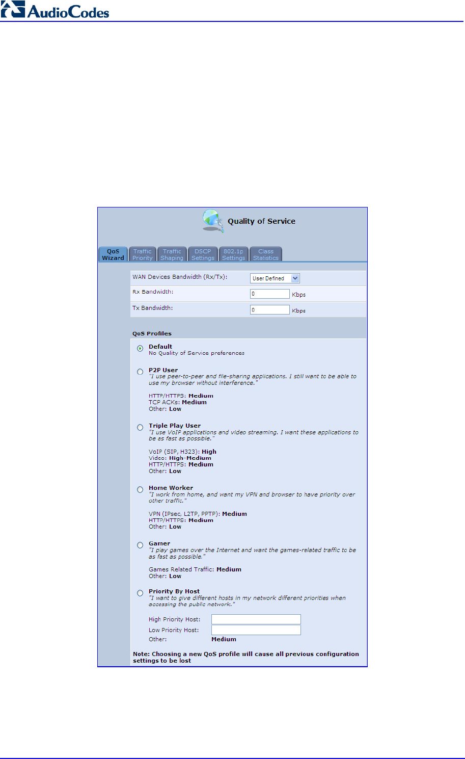
MP252 Multimedia Home Gateway 114 Document #: LTRT-23504
User's Manual
11.1 QoS Wizard
The QoS wizard allows you to configure your QoS parameters according to predefined
profiles, with just a few clicks. A chosen QoS profile automatically defines QoS rules, which
you can view and edit in the rest of the QoS tab screens.
The QoS wizard also allows you to define the WAN bandwidth.
To use the QoS Wizard:
1. From the menu bar, click the QoS menu link; the ‘Quality of Service’ screen appears
with the QoS Wizard tab selected by default.
Figure 11-1: QoS Wizard Tab Screen
2. Define bandwidth limitation. From the 'WAN Devices Bandwidth (Rx/Tx)' drop-down list,
select ‘User Defined’ if you want to define specific Rx and Tx bandwidth limitations, or
select the Rx/Tx optional values provided in the drop-down list.

MP252 Multimedia Home Gateway 11. Quality of Service
Version 3.4.0 115 June 2011
3. In the QoS Profiles group, select a QoS profile.
4. Click OK.
Note: Selecting a new QoS profile deletes all previous QoS settings.
11.2 Traffic Shaping
Traffic Shaping is the solution for managing and avoiding congestion where a high speed
LAN meets limited broadband bandwidth. A user may have, for example, a 100 Mbps
Ethernet LAN with a 100 Mbps WAN interface router. The router may communicate with the
ISP using a modem with a bandwidth of 2 Mbps. This typical setup makes the modem,
having no QoS module, the bottleneck. The router sends traffic as fast as it is received, while
its well-designed QoS algorithms are left unused. Traffic shaping limits the bandwidth of the
router, artificially forcing the router to be the bottleneck.
A traffic shaper is essentially a regulated queue that accepts uneven and/or bursty flows of
packets and transmits them in a steady, predictable stream so that the network is not
overwhelmed with traffic.
While Traffic Priority allows basic prioritization of packets, Traffic Shaping provides more
sophisticated definitions such as:
Bandwidth limit for each device
Bandwidth limit for classes of rules
Prioritization policy
TCP serialization on a device
You can also define QoS traffic shaping rules for a default device. These rules are used on a
device that has no definitions of its own. This enables the definition of QoS rules on Default
WAN, for example, and their maintenance even if the PPP or bridge device over the WAN is
removed.
MP252 also supports dynamic traffic shaping during a call. Traffic shaping is critical in
residential VoIP gateways because of the bottleneck created in the ADSL or Cable modem,
mainly in the upload direction. Dynamic traffic shaping ensures a minimum bandwidth for
VoIP calls. Without dynamic traffic shaping, traffic shaping limits the bandwidth at all times,
even if the user is not making a VoIP call and therefore, the service provider needs to
configure the QoS traffic shaping transmit (Tx) bandwidth according to the user's specific
upload bandwidth. Configuring a lower value results in a lower upload bandwidth (not only
during VoIP calls).
Dynamic traffic shaping enables the service provider to configure two upload traffic shaping
bandwidth parameters:
"Tx Bandwidth" - for all traffic
"Tx Bandwidth during Call" - for VoIP calls
MP252 normally uses the "Tx Bandwidth" value. When the user makes a VoIP call (i.e. any
phone/s connected to MP252 is ringing or off-hook), MP252 switches to use the "Tx
Bandwidth during Call" value.
11.2.1 Device Traffic Shaping
The procedure below describes how to configure traffic shaping.
To add a traffic shaping device:
1. From the menu bar, click the QoS menu, and then click the Traffic Shaping tab.
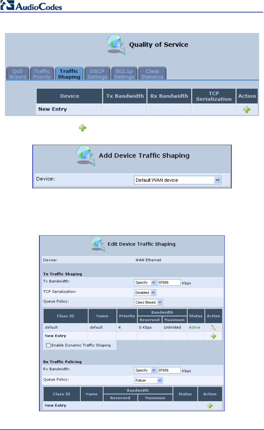
MP252 Multimedia Home Gateway 116 Document #: LTRT-23504
User's Manual
Figure 11-2: Quality of Service – Traffic Shaping Screen
2. Click the New icon; the 'Add Device Traffic Shaping’ screen appears.
Figure 11-3: Add Device Traffic Shaping Screen
3. From the ‘Device’ drop-down list, select the device for which you want to shape traffic.
The list includes all interfaces (e.g., All LAN Devices, All WAN Devices) and VPNs such
as PPoE, PPTP and L2TP (if defined). For example, select 'WAN Ethernet', and then
click OK; the ’Edit Device Traffic Shaping’ screen appears.
Figure 11-4: Edit Device Traffic Shaping Screen

MP252 Multimedia Home Gateway 11. Quality of Service
Version 3.4.0 117 June 2011
4. Under the Tx Traffic Shaping group, from the ‘Tx Bandwidth’ drop-down list, select
‘Specify’ and define the MP252’s maximum transmission bandwidth rate in the
corresponding field. The purpose is to limit the bandwidth of the WAN interface to that of
the weakest outbound link, for instance, the DSL speed provided by the ISP. This forces
MP252 to be the network bottleneck, where sophisticated QoS prioritization can be
performed. If the device’s bandwidth is not limited correctly, the bottleneck is an
unknown router or modem on the network path, rendering MP252 QoS useless. To
configure unlimited bandwidth, select ‘Unlimited’.
5. Under the Rx Traffic Policing group, from the ‘Rx Bandwidth’ drop-down list, select
‘Specify’ and define the MP252’s maximum receive bandwidth rate in the corresponding
field. This limits MP252’s bandwidth receipt rate to that of the DSL modem.
6. From the ‘TCP Serialization’ drop-down list, select whether to enable TCP serialization.
The screen refreshes, displaying the ’Maximum Delay’ field. This allows you to define
the maximum allowed transmission time frame (in milliseconds) of a single packet. Any
packet that requires a longer time to be transmitted is fragmented to smaller sections.
This avoids transmission of large, bursty packets that may cause delay or jitter for
real-time traffic such as VoIP.
7. Select the ‘Enable Dynamic Traffic Shaping’ check box if you want to configure traffic
shaping specifically for VoIP calls (see Section 11.2 on page 115). When selected, the
‘Tx Bandwidth During VoIP Call’ field appears. Enter the bandwidth for VoIP calls.
MP252 normally uses the "Tx Bandwidth" parameter value. When the user makes a
VoIP call (i.e. any phone connected to MP252 is ringing or off-hook), MP252 switches to
use the "Tx Bandwidth during Call" parameter value.
11.2.2 Shaping Classes
The bandwidth of a device can be divided to reserve constant portions of bandwidth to
user-defined traffic types. Such a portion is known as a Shaping Class. When not used by its
user-defined traffic type or owner (for example, VoIP), the class is then available to all other
traffic. However when needed, the entire class is reserved solely for its owner. Moreover, you
can limit the maximum bandwidth that a class can use even if the entire bandwidth is
available.
When a shaping class is defined for a specific traffic type, two shaping classes are created.
The second class is the 'Default Class', responsible for all the packets that do not match the
defined shaping class or any other classes that may be defined on the device. This can be
viewed in the Class Statistics screen.
To add a shaping class:
1. From the menu bar, click the QoS menu, and then click the Traffic Shaping tab.
2. Click the Edit icon corresponding to the added Device (e.g., WAN); the 'Edit Device
Traffic Shaping' screen appears.
3. Under the Tx Traffic Shaping group, click the New icon; the 'Add Shaping Class'
screen appears.
Figure 11-5: Add Shaping Class Screen
4. In the ‘Name’ field, enter a name for the class, and then click OK; the 'Edit Device Traffic
Shaping' screen appears.

MP252 Multimedia Home Gateway 118 Document #: LTRT-23504
User's Manual
5. Edit the newly added shaping class, by clicking the corresponding Edit icon; the 'Edit
Shaping Class' screen appears.
Figure 11-6: Edit Shaping Class
6. In the ‘Name’ field, modify the class name, if required.
7. From the ‘Class Priority’ drop-down list, select the priority level for the class, where zero
is the highest and seven the lowest.
8. In the ‘Bandwidth’ field, define the bandwidth for the class:
• Reserved: reserved (i.e., guaranteed) bandwidth (Committed Information Rate /
CIR) in kbps.
• Maximum: specify the maximum bandwidth
9. From the ‘Policy’ drop-down list, select the policy for routing packets within the class:
• Priority: Priority queuing uses multiple queues so that traffic is distributed among
queues based on priority. This priority is defined according to packet priority, which
can be defined explicitly by a DSCP value or an 802.1p value.
• FIFO: First In First Out. This priority queue ignores any previously-marked packet
priority.
• Fairness: The fairness algorithm ensures no starvation by granting all packets a
certain level of priority.
• RED: Random Early Detection. Utilizes statistical methods to drop packets in a
‘probabilistic’ way before queues overflow. Dropping packets in this way slows a
source down enough to keep the queue steady and reduces the number of packets
that would be lost when a queue overflows and a host is transmitting at a high rate.
10. From the ‘Schedule’ drop-down list, select the scheduler rule (defined in Section 4.5.1
on page 47) that defines the time segments during which the class can be active. By
default, the class is always active.
11. Click OK to save your settings.
11.2.2.1 Class Rules
Class rules define which packets belong to the class. Without class rules, the shaping class
has no effect. Each class can have outbound and inbound rules for outgoing and incoming
traffic respectively. For example, you can define that all outgoing packets from computer A in
your LAN belong to your VoIP class. These packets are limited to the class settings
(bandwidth, schedule, etc.). In addition, you can define the traffic protocol and priority for
each rule (this is not mandatory as in Traffic Priority rules).
11.2.2.1.1 Inbound and Outbound Data

MP252 Multimedia Home Gateway 11. Quality of Service
Version 3.4.0 119 June 2011
MP252 can control outgoing data easily. It can queue packets, delay them, give precedence
to other packets, or drop them. This helps in resolving upload (Tx) traffic bottlenecks and in
most cases is sufficient. However, in the case of download (Rx) traffic bottlenecks, the ability
to control the flow is much more limited. MP252 cannot queue packets, since in most cases
the LAN is much faster than the WAN and when MP252 receives a packet from the WAN, it
passes it immediately to the LAN.
QoS for ingress data has the following limitations, which do not exist for outgoing data:
QoS can only be applied to TCP streams (UDP streams cannot be delayed)
No borrowing mechanism
When reserving Rx bandwidth, it is strictly taken from the bandwidth of all other classes

MP252 Multimedia Home Gateway 120 Document #: LTRT-23504
User's Manual
In addition, MP252 cannot control the behavior of its WAN (usually the ISP), which may not
have proper QoS handling. Let’s look at a scenario of downloading a large file and surfing the
Internet at the same time. Downloading the file is distinguished by small requests, followed
by very large responses. This may result in blocking HTML traffic at the ISP. A solution for
such a scenario is limiting the bandwidth of low-priority TCP connections (such as file
download).
To add outbound and inbound class rules, see 11.3 on page 120.
Note: The hierarchy of the class rules is determined by the order of their addition to the
class. For example, if your first rule is match packets with any source address,
any destination address, and any protocol to this class; then all packets
traversing MP252 are associated with the specific class. Any rules defined later
do not have any effect.
11.3 Traffic Priority
Traffic Priority allows you to manage and avoid traffic congestion by defining inbound and
outbound priority rules for each device on your MP252. These rules determine the priority
assigned to packets traveling through the device. QoS parameters (DSCP marking and
packet priority) are set per packet, on an application basis.
You can set QoS parameters using flexible rules, according to the following parameters:
Source/destination IP address, MAC address or host name
Device
Source/destination ports
Limit the rule to specific days and hours
MP252 supports two priority marking methods for packet prioritization:
DSCP
802.1p Priority
The matching of packets by rules is connection-based, known as Stateful Packet Inspection
(SPI), using the same connection-tracking mechanism used by the firewall. Once a packet
matches a rule, all subsequent packets with the same attributes receive the same QoS
parameters, both inbound and outbound.
A packet can match more than one rule, and therefore:
The first class rule has precedence over all other class rules (scanning is stopped once
the first rule is reached).
The first traffic-priority (classless) rule has precedence over all other traffic-priority rules.
There is no prevention of a traffic-priority rule conflicting with a class rule. In this case,
the priority and DSCP setting of the class rule (if given) takes precedence.
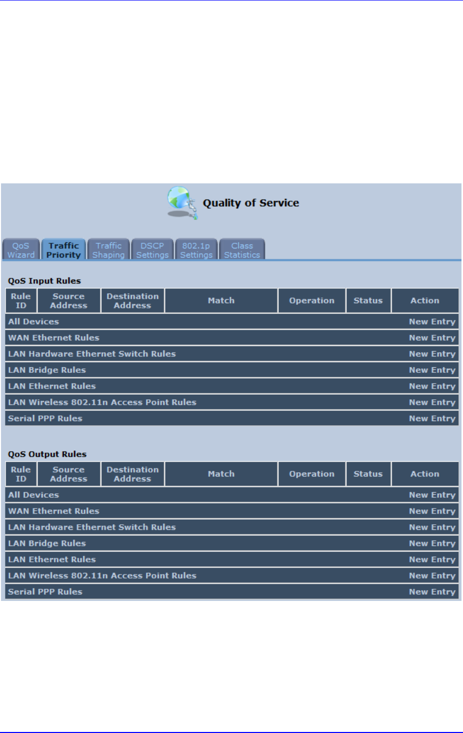
MP252 Multimedia Home Gateway 11. Quality of Service
Version 3.4.0 121 June 2011
Connection-based QoS also allows inheriting QoS parameters by some of the applications
that open subsequent connections. For instance, you can define QoS rules on SIP and the
rules then apply to both control and data ports (even if the data ports are unknown). This
feature applies to all applications that have ALG at firewall:
Any
User Defined (FTP, HTTP, HTTPS, TFTP, IMAP, PING, POP3, SNMP, SMTP, Telnet,
L2TP, Traceroute or any other protocol)
To set traffic priority rules:
1. From the menu bar, click the QoS menu, and then select the Traffic Priority tab; the
'Traffic Priority' screen appears.
Figure 11-7: Traffic Priority Screen
This screen is divided into two identical groups - ’QoS Input Rules’ and ’QoS Output
Rules’ - for prioritizing inbound and outbound traffic respectively. Each group lists all the
devices on which rules can be set. You can set rules on all devices at once by clicking
the New Entry link corresponding to 'All Devices'
2. After clicking the appropriate New Entry link, the 'Add Traffic Priority Rule' screen
appears.
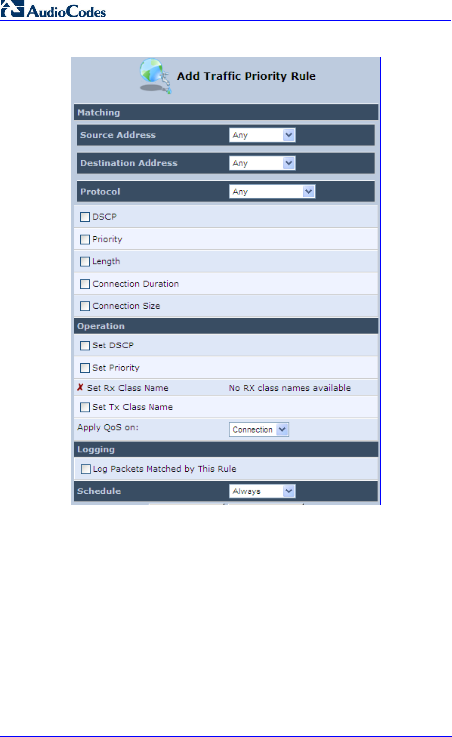
MP252 Multimedia Home Gateway 122 Document #: LTRT-23504
User's Manual
Figure 11-8: Add Traffic Priority Rule Screen
3. Under the Matching group, configure the matching characteristics:
a. From the ‘Source Address’ drop-down list, select 'Any', 'User Defined' or the host
as the source address of the packets sent to or received from the network object. If
you have created network objects (see Section 4.5.2 on page 50), then these are
also displayed in the list (or you can create one by selecting ‘User Defined’).
b. From the ‘Destination Address’ drop-down list, select the network object for the
destination address of the packets sent to or received from the network object. See
Step 3 above for a detailed explanation on the options.
c. From the ‘Protocol’ drop-down list, select the protocol. You can apply the rule to all
protocols (i.e., ‘Any’) or select an already defined protocol. You can create a new
protocol by selecting ‘User Defined’, and then following the procedure described in
Section 4.5.3 on page 51.
d. To match DSCP, select the ‘DSCP’ check box, and then enter the DSCP markings.
e. To match priority, select the ‘Priority’ check box, and then select the priority of the
packets.

MP252 Multimedia Home Gateway 11. Quality of Service
Version 3.4.0 123 June 2011
f. To match the Device, select the ‘Device’ check box, and then select the Device
interface.
g. To match packet or data length, select the ‘Length’ check box, and then enter the
data or packet length.
h. To match connection duration, select the ‘Connection Duration’ check box, and
then enter the duration of the connection (greater or less than).
i. To match connection size, select the ‘Connection Size’ check box, and then enter
the connection size.
4. Under the Operation group, configure the QoS operation:
a. Select the ‘Set DSCP’ check box to mark a DSCP value on packets matching this
rule and then enter the hexadecimal value of the DSCP.
b. Select the ‘Set Priority’ check box to add a priority to the rule and then select the
priority level (where 0 is the lowest and 7 the highest). This sets the priority of a
packet on the connection matching the rule, while routing the packet.
c. Select the ‘Tx Class Name’ check box, and then select the class name that you
defined.
d. From the ‘Apply QoS on’ drop-down list, select whether you want to apply the QoS
rule on the connection or on the packet.
5. Select the ‘Log Packets Matched by This Rule’ check box to log the first packet from a
connection that matches by this rule.
6. From the ‘Schedule’ drop-down list, select the time segments during which the rule may
be active. By default, the rule is always active (i.e., ‘Always’). If you have defined
Scheduler rules (see Section 4.5.1 on page 47), then these are also displayed as
options. To define a new one Scheduler rule, select ‘User Defined’.
7. Click OK to save the settings.
11.4 DSCP Mapping
To understand Differentiated Services Code Point (DSCP), one must first be familiarized with
the Differentiated Services (DiffServ) model. DiffServ is a Class of Service (CoS) model that
enhances best-effort Internet services by differentiating traffic by users, service requirements
and other criteria. Packets are specifically marked, allowing network nodes to provide
different levels of service, as appropriate for voice calls, video playback or other
delay-sensitive applications, via priority queuing or bandwidth allocation, or by choosing
dedicated routes for specific traffic flows.
DiffServ defines a field in IP packet headers referred to as DSCP. Hosts or routers passing
traffic to a DiffServ-enabled network typically mark each transmitted packet with an
appropriate DSCP. The DSCP markings are used by DiffServ network routers to
appropriately classify packets and to apply particular queue handling or scheduling behavior.
MP252 provides a table of predefined DSCP values, which are mapped to 802.1p priority
marking method. You can edit or delete any of the existing DSCP setting, as well as add new
entries.
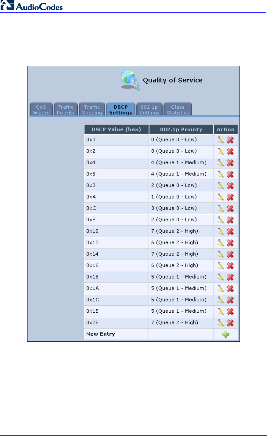
MP252 Multimedia Home Gateway 124 Document #: LTRT-23504
User's Manual
To view and set DSCP rules:
1. From the menu bar, click the QoS menu link, and then click the DSCP Settings tab; the
following screen appears:
Figure 11-9: DSCP Settings Screen
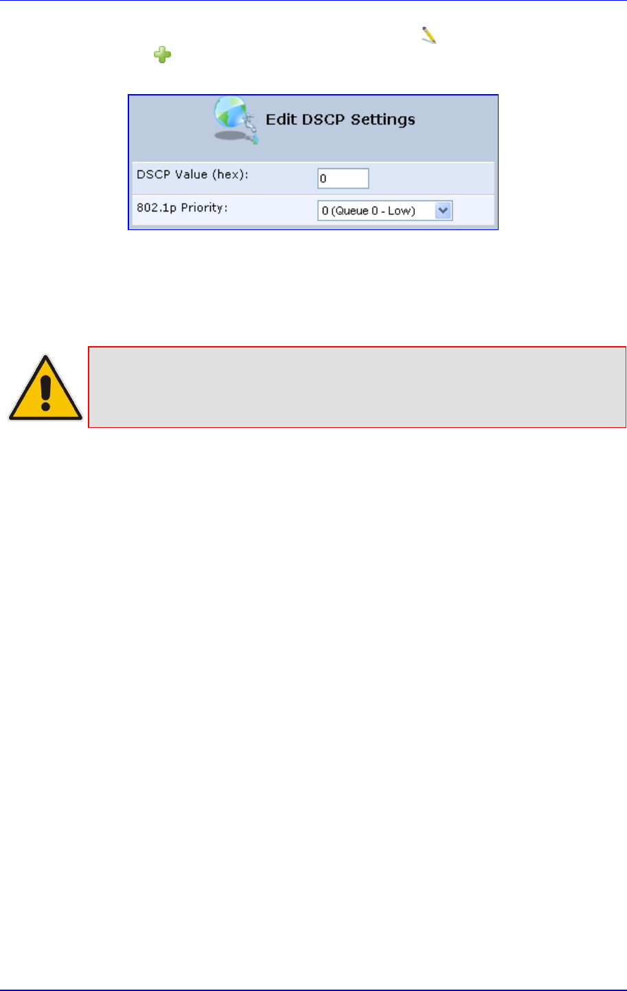
MP252 Multimedia Home Gateway 11. Quality of Service
Version 3.4.0 125 June 2011
2. To edit an existing entry, click its corresponding Edit icon. To add a new entry, click
the New icon. In both cases, the ’Edit DSCP Settings’ screen appears:
Figure 11-10: Edit DSCP Settings
3. In the ‘DSCP Value (hex)’ field, enter a hexadecimal number for the DSCP value.
4. In the ‘802.1p Priority’ drop-down list, select an 802.1p priority level (each priority level
is mapped to low, medium, or high priority).
5. Click OK to save your settings.
Note: The DSCP value overriding the priority of incoming packets with an unassigned
value (priority 0, assumed to be a no-priority-set) is ‘0x0’. By default, this value is
mapped to 802.1p priority level ‘0 -Low’, which means that such packets receive
the lowest priority.
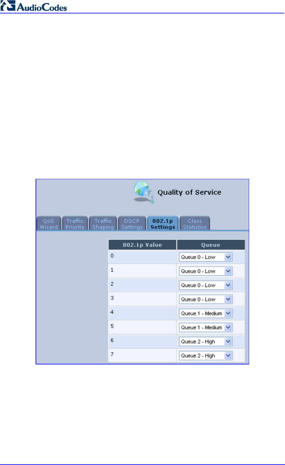
MP252 Multimedia Home Gateway 126 Document #: LTRT-23504
User's Manual
11.5 802.1p Mapping
The IEEE 802.1p priority marking method is a standard for prioritizing network traffic at the
data link/MAC sub-layer. 802.1p traffic is simply classified and sent to the destination, with no
bandwidth reservations established.
The 802.1p header includes a 3-bit prioritization field, which allows packets to be grouped
into eight levels of priority. MP252 maps these eight levels to three main priorities: high,
medium and low. By default, values six and seven are mapped to high priority, which may be
assigned to network-critical traffic. Values four and five are mapped to medium priority, which
may be applied to delay-sensitive applications, such as interactive video and voice. Values
three to zero are mapped to low priority, which may range from controlled-load applications
down to ‘loss eligible’ traffic. The zero value is normally used for best-effort traffic. It is the
default value for traffic with unassigned priority.
To set 802.1p rules:
1. From the menu bar, click the QoS menu link, and then click the 802.1p Settings tab; the
following screen appears:
Figure 11-11: 802.1p Settings Screen
2. The eight 802.1p values are pre-configured with the three priority levels: high, medium
and low. You can change these levels for each of the eight values in their respective
drop-down list.
3. Click OK to save the settings.
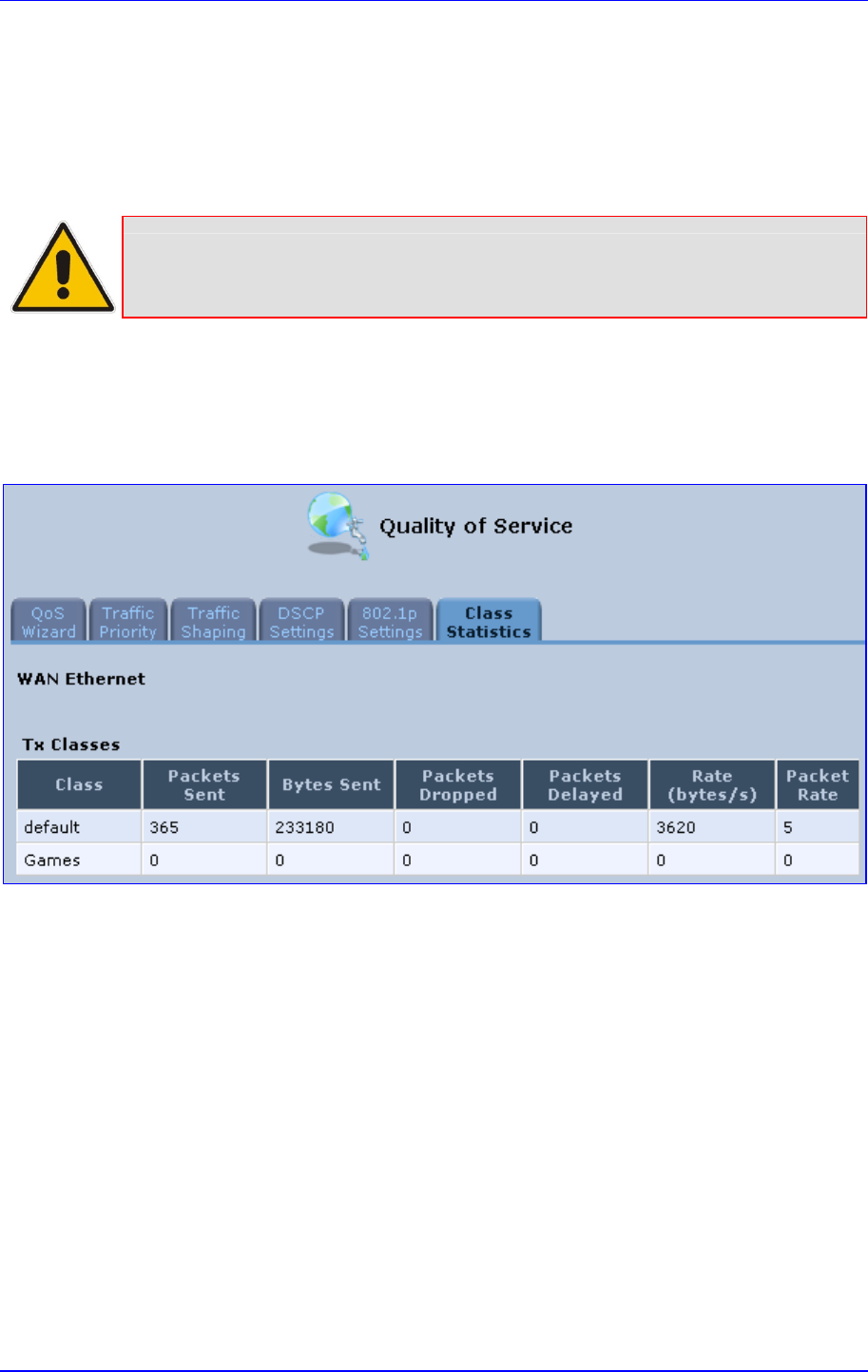
MP252 Multimedia Home Gateway 11. Quality of Service
Version 3.4.0 127 June 2011
11.6 Class Statistics
MP252 provides accurate, real-time information on the traffic passing through your defined
device classes. For example, the amount of packets sent, dropped, or delayed are just a few
of the parameters that you can monitor per each shaping class.
Note: Class statistics are available only if you have defined at least one class
(otherwise no information is displayed).
To view your class statistics:
From the menu bar, click the QoS menu link, and then click the Class Statistics tab;
the following screen appears:
Figure 11-12: Class Statistics Screen

MP252 Multimedia Home Gateway 128 Document #: LTRT-23504
User's Manual
11.7 Configuring Basic VoIP QoS
The 'Traffic Shaping' feature only ensures priority to calls that originate from inside MP252.
When giving VoIP priority over data, the bottleneck is effectively moved from the Cable /
ADSL modem into MP252. To give priority to calls from the LAN, you must define a traffic
priority rule (for SIP and RTP from the device on the LAN).
This section recommends a minimal QoS configuration that ensures sufficient QoS for VoIP
calls when MP252 is connected behind a broadband (cable or DSL) modem with limited
uplink bandwidth and the user runs bandwidth-consuming applications on the PC.
Since most modems do not have any priority mechanisms, the Tx bandwidth of MP252
should be limited according to the modem’s uplink bandwidth. Since MP252 automatically
gives higher priority to VoIP packets (in its internal queues), it is not necessary to define
traffic shaping classes.
To configure basic QoS for VoIP:
1. From the menu bar, click the QoS menu link, and then click the Traffic Shaping tab; the
‘Traffic Shaping’ screen appears.
2. Click the New icon; the screen 'Add Device Traffic Shaping' appears.
3. From the 'Device' drop-down list, select 'Default WAN Device' (or your PPTP/L2TP
connection you have created), and then click OK; the 'Edit Device Traffic Shaping'
screen appears.
4. Limit the Tx bandwidth (in the 'Tx Bandwidth' field) according to your modem’s uplink
bandwidth.
5. To prevent jitter in outgoing RTP packets, from the 'TCP Serialization' drop-down list,
select 'Enabled', and then in the 'Maximum Delay' field, define the maximum allowed
delay (e.g. 20 milliseconds). This causes long TCP packets to be fragmented when
there is an active voice call.
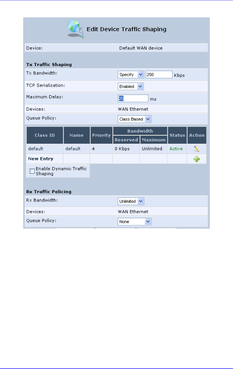
MP252 Multimedia Home Gateway 11. Quality of Service
Version 3.4.0 129 June 2011
Figure 11-13: Edit Device Traffic Shaping
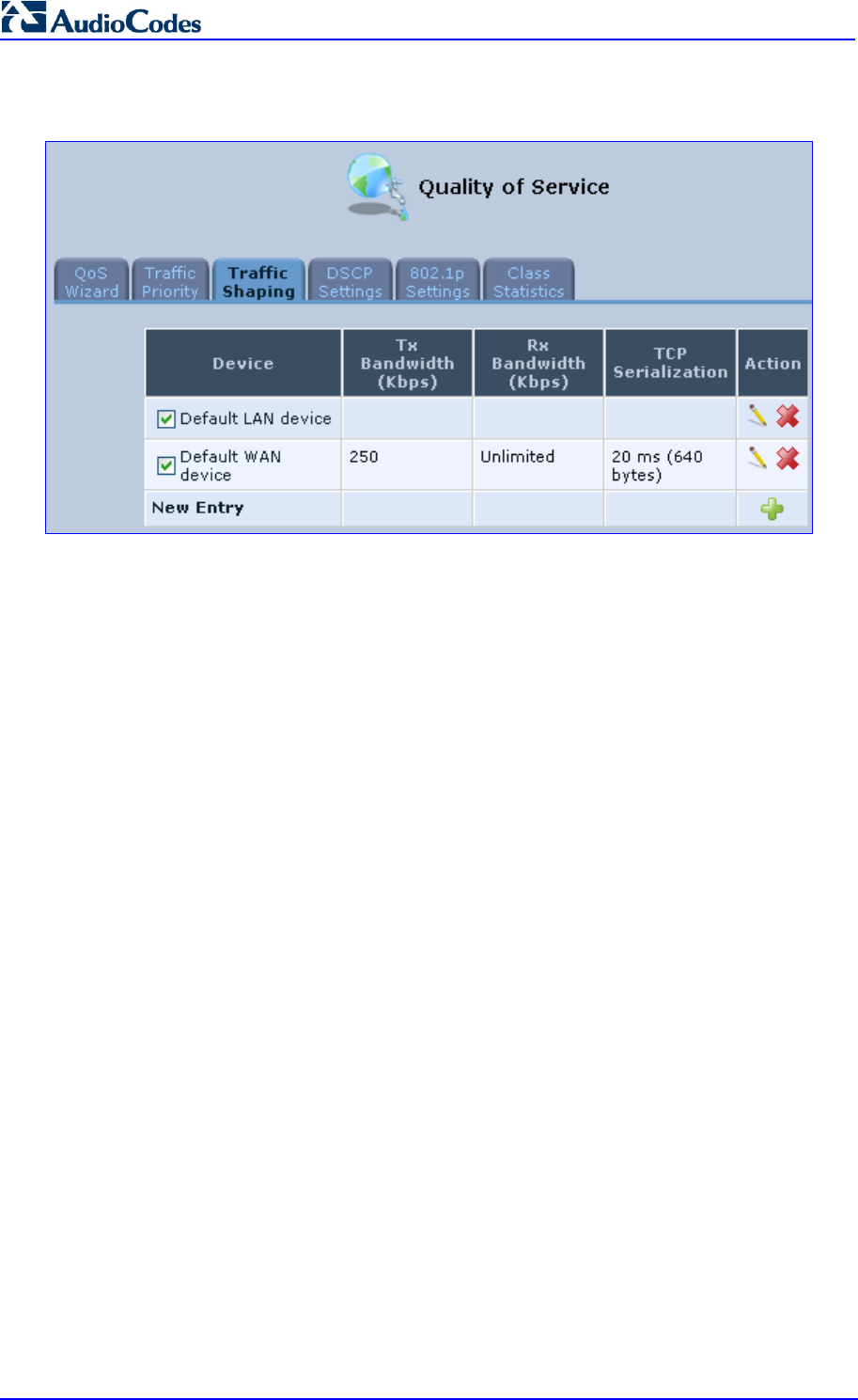
MP252 Multimedia Home Gateway 130 Document #: LTRT-23504
User's Manual
6. Click OK to apply the new definition.
Figure 11-14: QoS - Edit Device Traffic Shaping - Submitting the Configuration
7. Click OK again.

Version 3.4.0 131 July 2011
MP252 Multimedia Home Gateway 12. Network Connections
12 Network Connections
This chapter provides a detailed description on how to configure the following network
connections:
WAN – see Section 12.1 on page 131
LAN – see Section 12.2 on page 151
VLANs – see Section 12.4 on page 181
LAN-WAN Bridging – see Section 12.5 on page 188
12.1 Configuring a WAN Connection
This section describes how to configure your WAN Internet (WAN Ethernet or WAN DSL)
connection.
The WAN connection is configured in the ‘Network Connections’ screen, which provides a
connection wizard that guides you through the network configuration stages.
Notes:
• To quickly configure a basic WAN connection, use the ‘Quick Setup’
screen, as described in Section 7.1 on page 63.
• Before configuring the MP252 Internet connection, ensure that you have
obtained relevant technical information on the Internet connection type from
your Internet Telephony Service Provider (ITSP). For example, whether you
are connected to the Internet using a static or dynamic IP add
ress, or what
protocols such as PPTP or PPPoE are used to communicate over the
Internet.
• MP252 automatically detects the physical WAN type (i.e., Ethernet or
ADSL). To change the WAN type, you must restore MP252 to factory
settings (see Section 18.8).
• When connected to ADSL, the LAN4/WAN Ethernet port can be used for
Ethernet LAN interface.
• When connected to an external modem through the Ethernet LAN4/WAN
port and MP252 obtains an IP address, the ADSL interface is disabled.
•
If the Automatic Dialer feature is shipped preconfigured (i.e., enabled), then
MP252 automatically detects the Internet dialer type and therefore, Internet
connection configuration is unnecessary. However, it is recommended to
manually configure the Internet connection after the Automatic Dialer
process has completed (successfully or not). For more information on the
Automatic Dialer feature, see Section 7.2 on page 72.
To start the Connection Wizard:
1. From the menu bar, click the Network Connections menu; the 'Network Connections'
screen appears.
Figure 12-1: Network Connections Screen
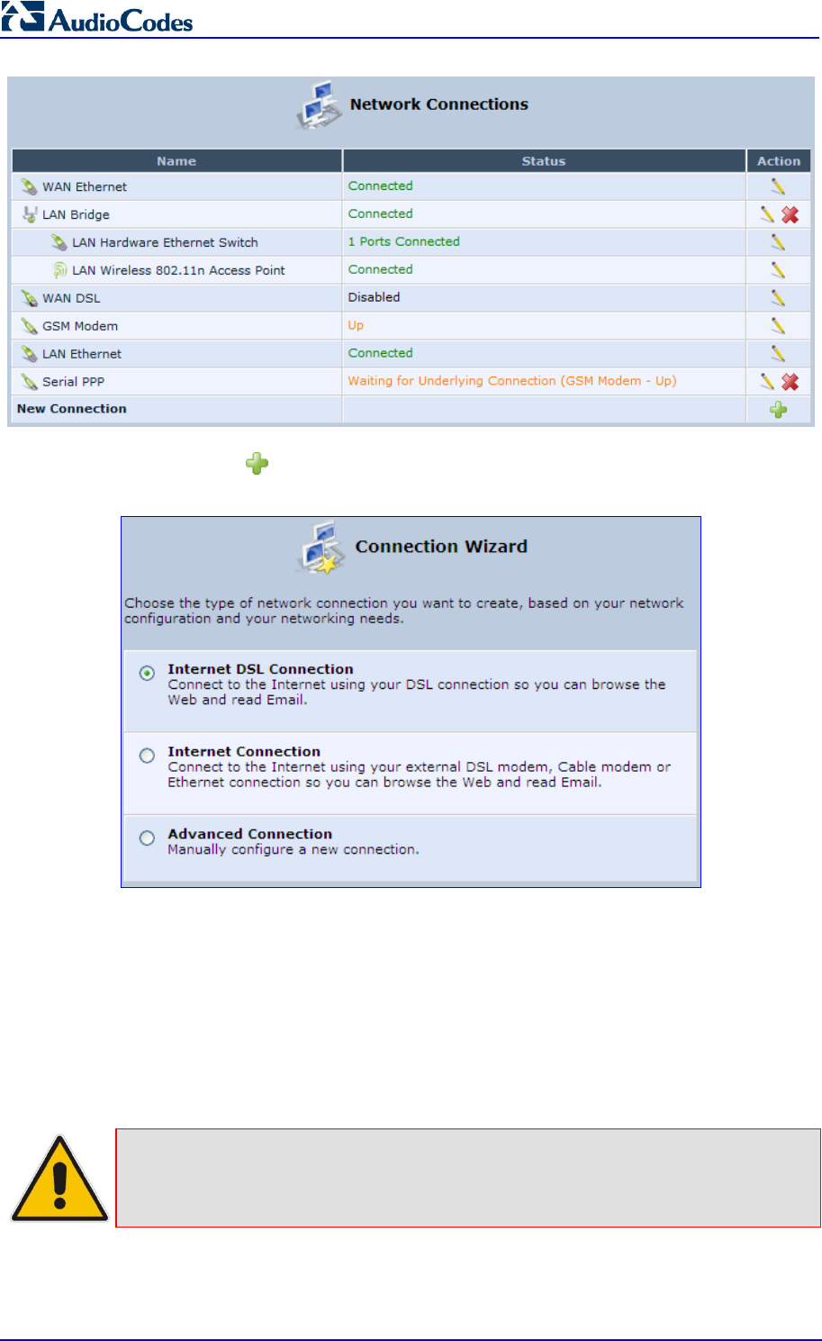
MP252 Multimedia Home Gateway 132 Document #: LTRT-23504
User's Manual
1. Click the New icon; the ‘Connection Wizard’ screen appears:
Figure 12-2: Connection Wizard Screen
2. Select the required network connection group:
• Internet DSL Connection: configures an Internet connection when using the
MP252 integrated DSL modem (see Section 12.1.1 on page 133)
• Internet Connection: configures an Internet connection when using an external
DSL modem, Cable modem or Ethernet connection modem (see Section 12.1.2 on
page 143)
• Advanced Connection: configures the WAN connection types as well as network
bridging and VLANs
Notes:
• For configuring VLANS, see Section 12.4 on page 181.
• For configuring network bridging, see Section 12.5 on page 188.
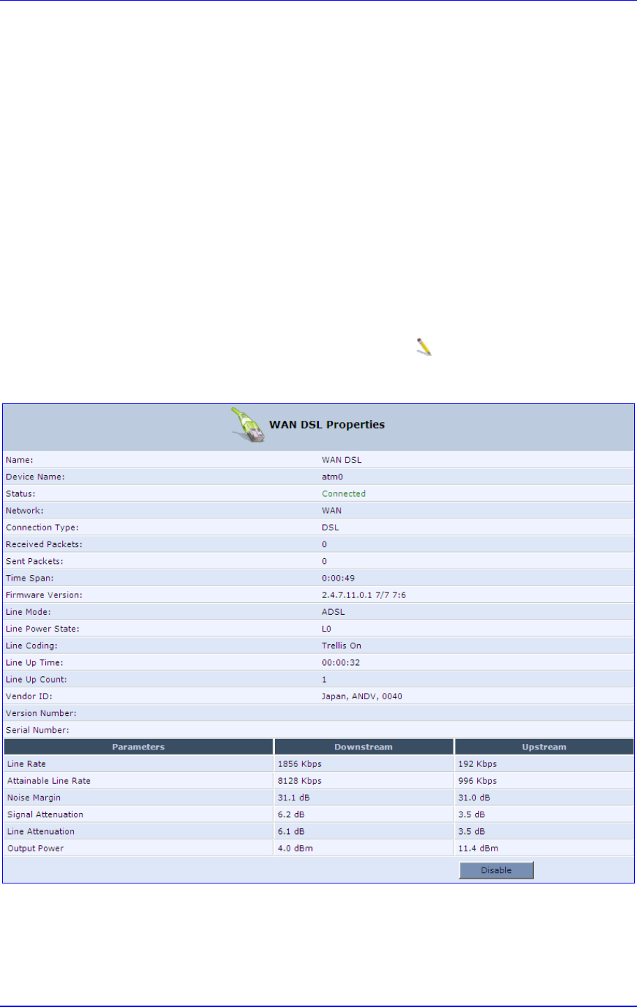
MP252 Multimedia Home Gateway 12. Network Connections
Version 3.4.0 133 June 2011
12.1.1 WAN DSL Connections
You can configure the following WAN DSL connection types:
Determine Protocol Type Automatically (PVC scan) – see Section 12.1.1.1 on page 133
Point-to-Point Protocol over Ethernet (PPPoE) – see Section 12.1.1.2 on page 134
Point-to-Point Protocol over ATM (PPPoA) – see Section 12.1.1.3 on page 136
Routed Ethernet Connection over ATM (Routed ETHoA) – see Section 12.1.1.4 on
page 138
LAN-WAN Bridged Ethernet Connection over ATM (Bridged ETHoA) – see Section
12.1.1.4 on page 138
Classical IP over ATM (CLIP) – see Section 12.1.1.5 on page 140
Routed IP over ATM (IPoA) – see Section 12.1.1.6 on page 142
If you have established a WAN DSL connection, you can view the properties of this
connection as described below.
To view the WAN DSL properties:
In the ‘Network Connections’ screen, click the Edit icon corresponding to the WAN
DSL network connection; the ‘WAN DSL Properties’ screen appears:
Figure 12-3: WAN DSL Properties Screen
12.1.1.1 Determine Protocol Type Automatically (PVC Scan)
The Determine Protocol Type Automatically (PVC Scan) connection type automatically
scans for a VPI/VCI pair, necessary when connecting to DSL. If such a pair is not found, your
service provider should supply you with one.
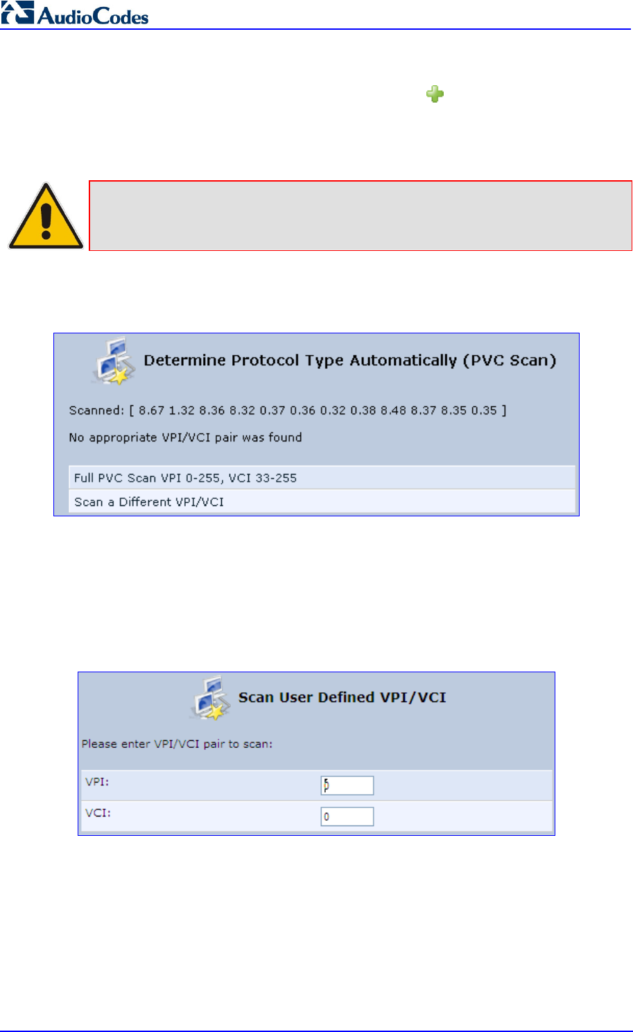
MP252 Multimedia Home Gateway 134 Document #: LTRT-23504
User's Manual
To automatically scan for a VPI / VCI pair:
1. In the 'Network Connections' screen, click the New icon; the 'Connection Wizard'
screen appears.
2. Select the Internet DSL Connection option, and then click Next; the 'Internet DSL
Connection' screen appears.
Note: You can also create a PVC connection using the Advanced Connection
option.
3. Select the Determine Protocol Type Automatically (PVC Scan) option, and then click
Next; the scan begins, refreshing the screen every few seconds to display the progress.
Figure 12-4: Determine Protocol Type Automatically (PVC Scan) Screen
You can click the following links:
Full PVC Scan VPI 0-255, VCI 33-255: initiates a longer, more thorough scan, between
VPI 0-255 and VCI 33-255.
Scan a Different VPI/VCI: scans for specific VPI/VCI pair. The 'Scan User Defined
VPI/VCI' screen appears (as shown below). Enter the VPI/VCI pair you wish to scan and
then click OK.
Figure 12-5: Scan User Defined VPI/VCI Screen
12.1.1.2 PPPoE
PPPoE relies on two widely accepted standards, PPP and Ethernet. PPPoE enables your
home network PCs that communicate on an Ethernet System network to exchange
information with PCs on the Internet. PPPoE supports the protocol layers and authentication
widely used in PPP and enables a point-to-point connection to be established in the normally
multipoint architecture of Ethernet. A discovery process in PPPoE determines the Ethernet
MAC address of the remote device to establish a session.
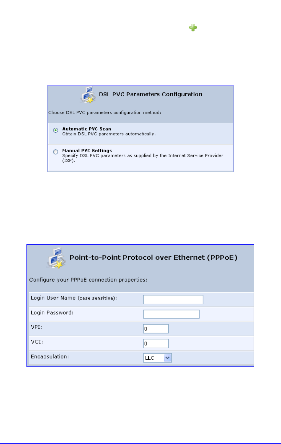
MP252 Multimedia Home Gateway 12. Network Connections
Version 3.4.0 135 June 2011
To create a PPPoE connection:
1. In the 'Network Connections' screen, click the New icon; the 'Connection Wizard'
screen appears.
2. Select the Internet DSL Connection option, and then click Next; the 'Internet DSL
Connection' screen appears.
3. Select the Point-to-Point Protocol over Ethernet (PPPoE) option, and then click Next;
the 'DSL PVC Parameters Configuration' screen appears.
Figure 12-6: DSL PVC Parameters Configuration Screen
4. Select one of the following options:
• Automatic PVC Scan: If you want to obtain the DSL PVC parameters
automatically
• Manual PVC Settings: If you do not want to obtain the DSL PVC parameters
automatically
5. Click Next; the 'Point-to-Point Protocol over Ethernet (PPPoE)' screen appears.
Figure 12-7: Point-to-Point Protocol over Ethernet (PPPoE) Screen
6. Enter your PPPoE login username and password (provided by your ITSP).
7. If you selected the Manual PVC Settings option in the previous step, you also need to
configure the following:
• VPI and VCI pair of identifiers.
• Encapsulation method - LLC, VCMux, or VCMux HDLC.
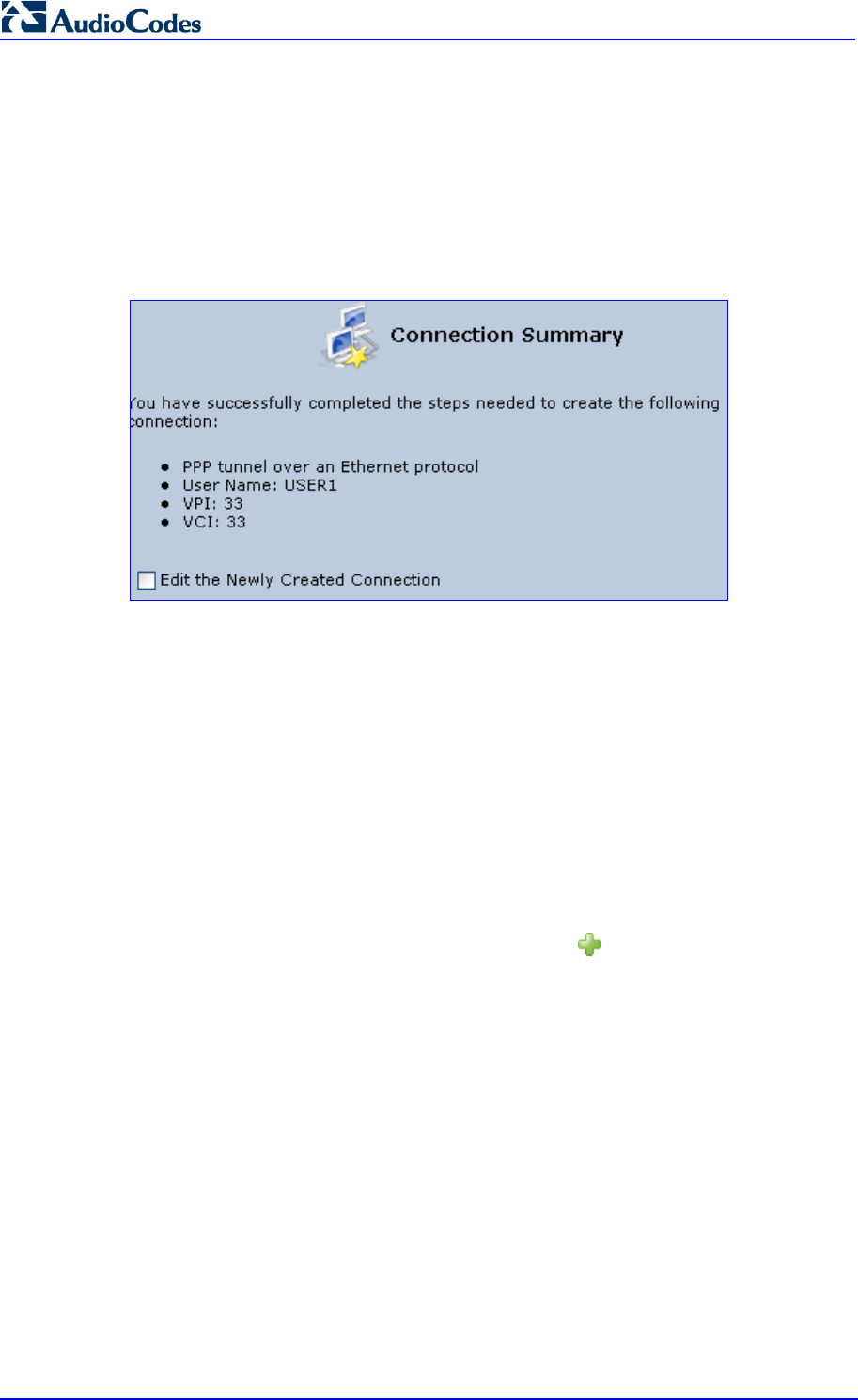
MP252 Multimedia Home Gateway 136 Document #: LTRT-23504
User's Manual
Asynchronous Transfer Mode (ATM) is a network technology based on transferring data
in cells or packets of a fixed size. The cell used with ATM is relatively small compared to
units used with other technologies. The small, constant cell size allows the transmission
of video, audio, and computer data, assuring that no single type of data consumes the
connection. ATM addressing consists of two identifiers that identify the virtual path (VPI)
and the virtual connection (VCI). A virtual path consists of multiple virtual channels to
the same endpoint.
8. Click Next; the 'Connection Summary' screen appears:
Figure 12-8: Connection Summary Screen
9. Select the 'Edit the Newly Created Connection' check box if you want to perform
additional configurations after clicking Finish.
10. Click Finish to save the settings; the new PPPoE connection is added to the ‘Network
Connections’ screen.
12.1.1.3 PPPoA
PPPoA is a standard for incorporating the popular PPP protocol into a DSL connection that
uses ATM as its networking protocol. From the PC, IP packets travel over an Ethernet
connection to the MP252, which encapsulates the PPP protocol to the IP packets and
transports them to the service provider's DSLAM over ATM.
To create a PPPoA connection:
1. In the 'Network Connections' screen, click the New icon; the 'Connection Wizard'
screen appears.
2. Select the Internet DSL Connection option, and then click Next; the 'Internet DSL
Connection' screen appears.
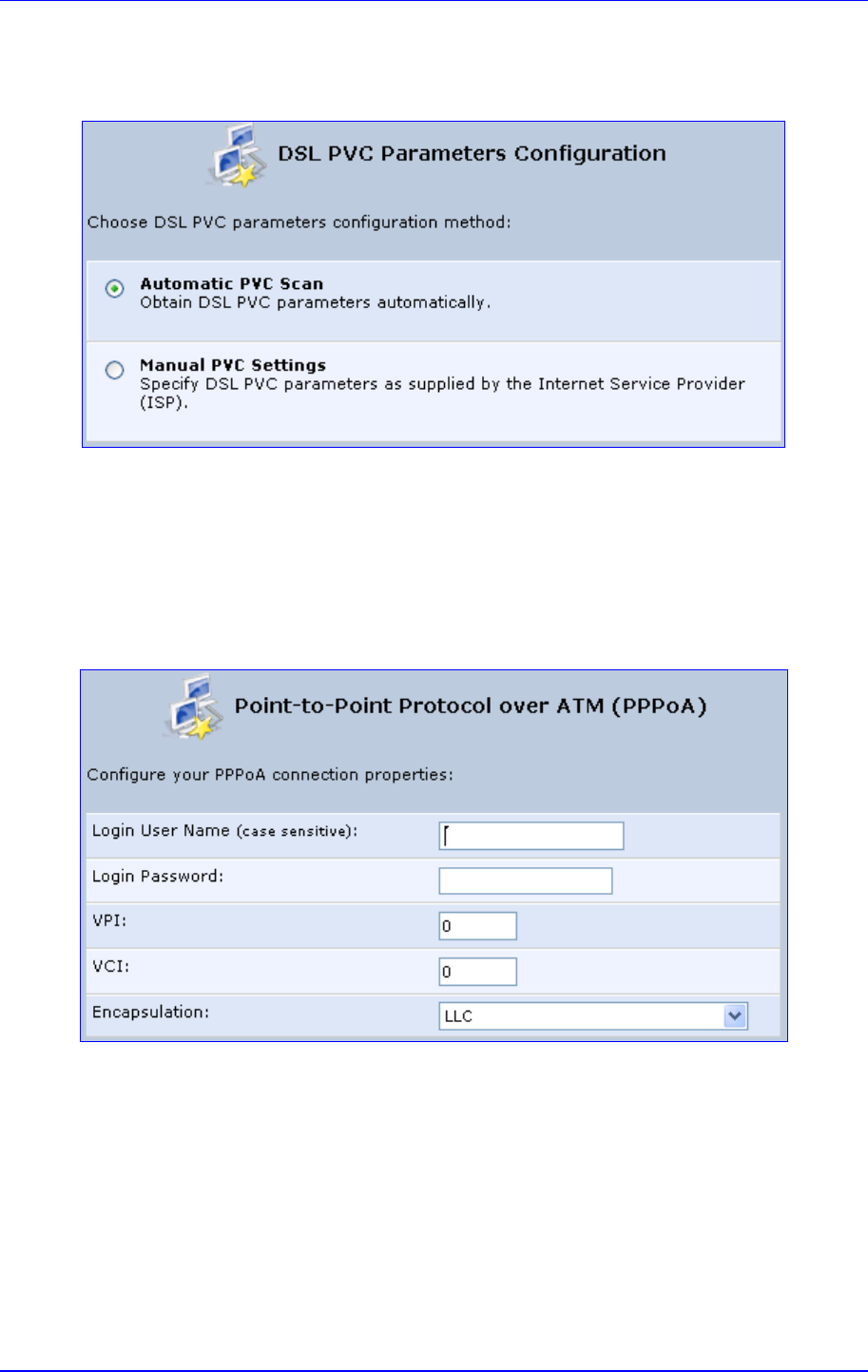
MP252 Multimedia Home Gateway 12. Network Connections
Version 3.4.0 137 June 2011
3. Select the Point-to-Point Protocol over ATM (PPPoA) option, and then click Next; the
'DSL PVC Parameters Configuration' screen appears.
Figure 12-9: DSL PVC Parameters Configuration Screen
4. Select one of the following options:
• Automatic PVC Scan: If you want to obtain the DSL PVC parameters
automatically
• Manual PVC Settings: If you do not want to obtain the DSL PVC parameters
automatically
5. Click Next; the 'Point-to-Point Protocol over ATM (PPPoA)' screen appears.
Figure 12-10: Point-to-Point Protocol over ATM (PPPoA) Screen
6. Enter your PPPoA login username and password (provided by your ITSP).
7. If you selected the Manual PVC Settings option in the previous step, you also need to
configure the following:
• VPI and VCI pair of identifiers.
• Encapsulation method - LLC, VCMux, or VCMux HDLC.
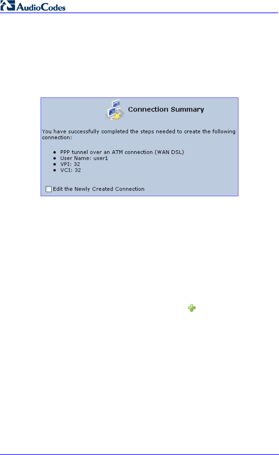
MP252 Multimedia Home Gateway 138 Document #: LTRT-23504
User's Manual
Asynchronous Transfer Mode (ATM) is a network technology based on transferring data
in cells or packets of a fixed size. The cell used with ATM is relatively small compared to
units used with other technologies. The small, constant cell size allows the transmission
of video, audio, and computer data, assuring that no single type of data consumes the
connection. ATM addressing consists of two identifiers that identify the virtual path (VPI)
and the virtual connection (VCI). A virtual path consists of multiple virtual channels to
the same endpoint.
8. Click Next; the 'Connection Summary' screen appears:
Figure 12-11: Connection Summary Screen
9. Select the 'Edit the Newly Created Connection' check box if you want to perform
additional configurations after clicking Finish.
10. Click Finish to save the settings; the new PPPoA connection is added to the ‘Network
Connections’ screen.
12.1.1.4 Routed ETHoA or Bridged ETHoA
The Ethernet over ATM (ETHoA) connection allows transport of Ethernet frames on DSL
connections. When creating an ETHoA connection, it is bridged to the LAN. You must
configure a dialup connection on the LAN computer with your ITSP’s user name and
password.
To create an ETHoA connection:
1. In the 'Network Connections' screen, click the New icon; the 'Connection Wizard'
screen appears.
2. Select the Internet DSL Connection option, and then click Next; the 'Internet DSL
Connection' screen appears.
3. Select one of the following options:
• Routed Ethernet Connection over ATM (Routed ETHoA):
a. Click Next; the 'DSL PVC Parameters Configuration' screen appears.
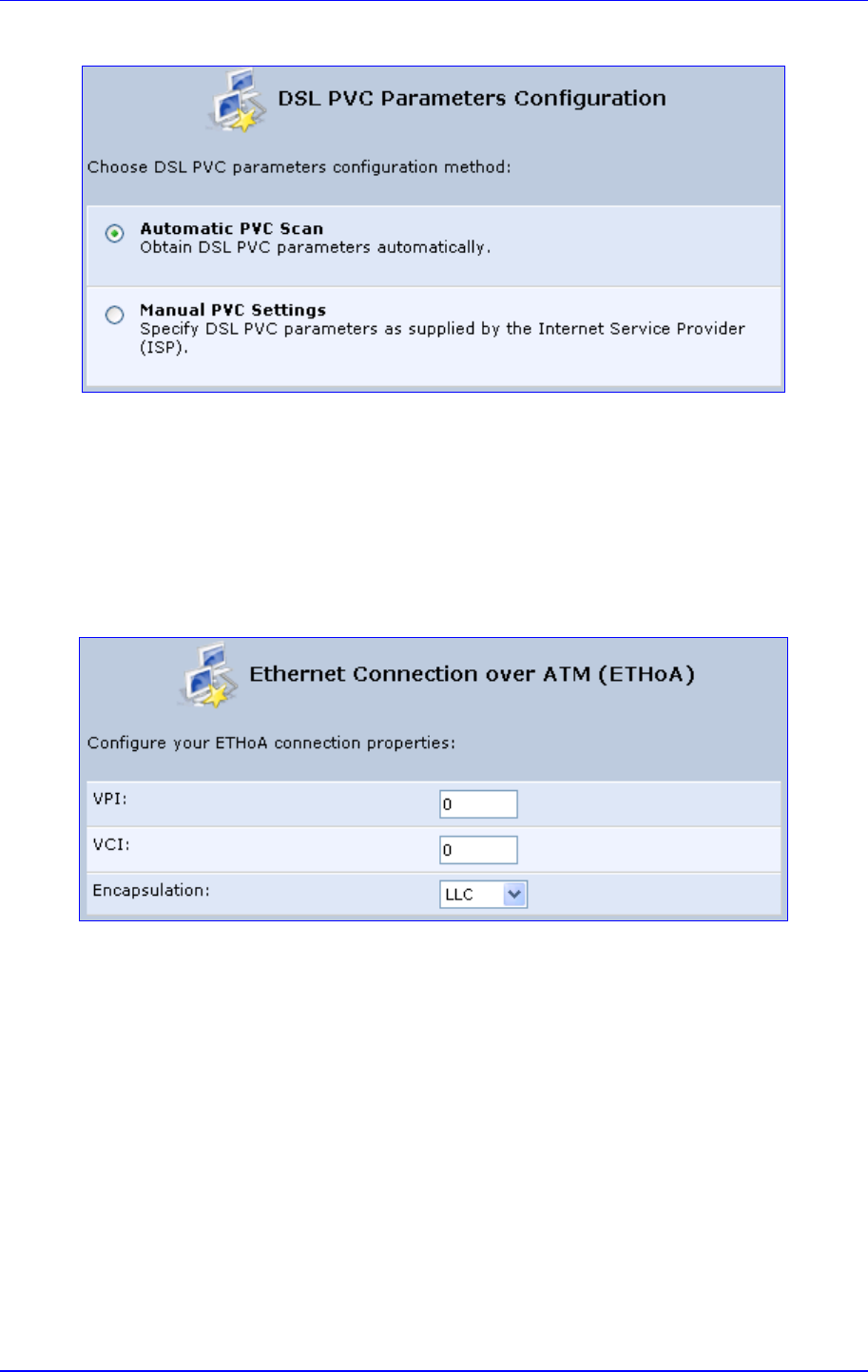
MP252 Multimedia Home Gateway 12. Network Connections
Version 3.4.0 139 June 2011
Figure 12-12: DSL PVC Parameters Configuration Screen
b. Select one of the following options:
Automatic PVC Scan: If you want to obtain the DSL PVC parameters
automatically
Manual PVC Settings: If you do not want to obtain the DSL PVC
parameters automatically
• LAN-WAN Bridged Ethernet Connection over ATM (Bridged ETHoA):
a. Click Next; the ‘Ethernet Connection over ATM (ETHoA)' screen appears.
Figure 12-13: Ethernet Connection over ATM (ETHoA) Screen
4. If you selected the Manual PVC Settings option, you also need to configure the
following:
• VPI and VCI pair of identifiers.
• Encapsulation method - LLC, VCMux, or VCMux HDLC.
Asynchronous Transfer Mode (ATM) is a network technology based on transferring data
in cells or packets of a fixed size. The cell used with ATM is relatively small compared to
units used with other technologies. The small, constant cell size allows the transmission
of video, audio, and computer data, assuring that no single type of data consumes the
connection. ATM addressing consists of two identifiers that identify the virtual path (VPI)
and the virtual connection (VCI). A virtual path consists of multiple virtual channels to
the same endpoint..

MP252 Multimedia Home Gateway 140 Document #: LTRT-23504
User's Manual
5. Click Next; the 'Connection Summary' screen appears:
Figure 12-14: Connection Summary Screen
6. Select the 'Edit the Newly Created Connection' check box if you want to perform
additional configurations after clicking Finish.
7. Click Finish to save the settings; the new ETHoA connection is added to the ‘Network
Connections’ screen.
12.1.1.5 CLIP
CLIP is a standard for transmitting IP traffic in an ATM network. IP protocols contain IP
addresses that have to be converted into ATM addresses, and Classical IP performs this
conversion, as long as the destination is within the same subnet. Classical IP does not
support routing between networks. The Classical IP-enabled driver in the end station sends
out an ARP request to a Classical IP-enabled ARP server, which returns the ATM address.
To create a CLIP connection:
1. In the 'Network Connections' screen, click the New icon; the 'Connection Wizard'
screen appears.
2. Select the Internet DSL Connection option, and then click Next; the 'Internet DSL
Connection' screen appears.
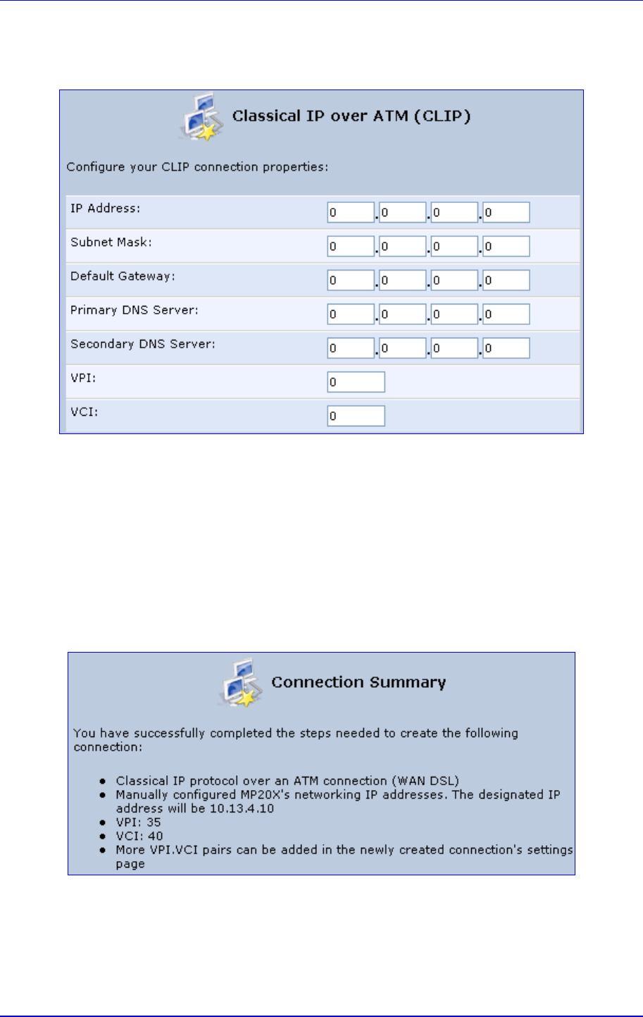
MP252 Multimedia Home Gateway 12. Network Connections
Version 3.4.0 141 June 2011
3. Select the Classical IP over ATM (CLIP) option, and then click Next; the ‘Classical IP
over ATM (CLIP)' screen appears.
Figure 12-15: Classical IP over ATM (CLIP) Screen
4. Enter the following information (provided by your ITSP):
• IP Address
• Subnet Mask
• Default Gateway
• Primary DNS Server
• Secondary DNS Server
• VPI and VCI pair of identifiers
5. Click Next; the 'Connection Summary' screen appears.
Figure 12-16: Connection Summary Screen
6. Select the 'Edit the Newly Created Connection' check box if you want to perform
additional configurations after clicking Finish.
7. Click Finish to save the settings; the new CLIP connection is added to the ‘Network
Connections’ list.
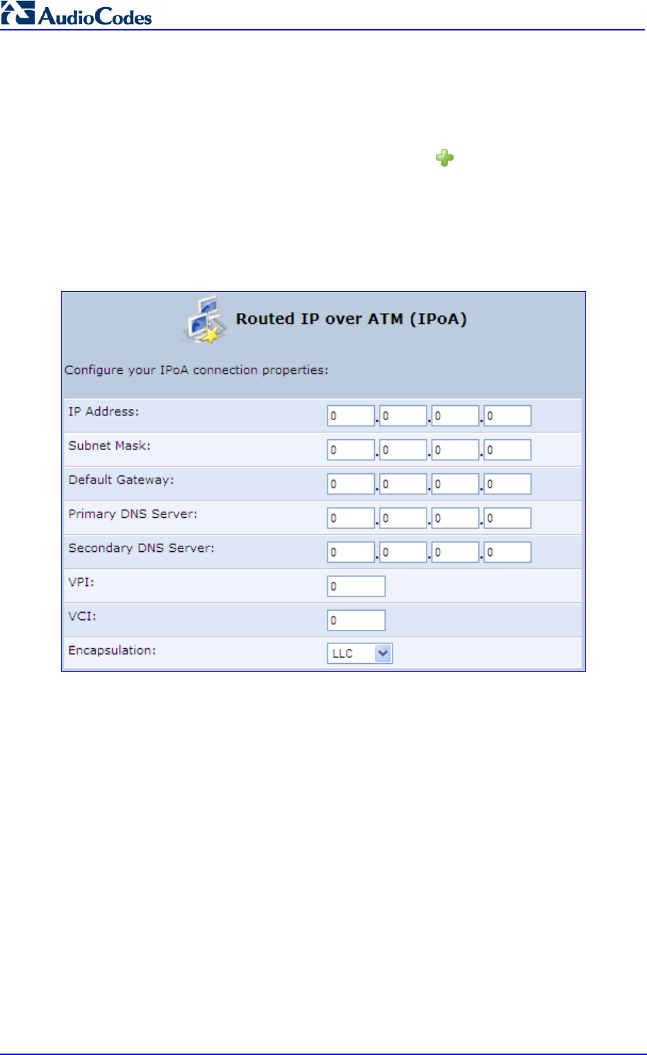
MP252 Multimedia Home Gateway 142 Document #: LTRT-23504
User's Manual
12.1.1.6 IPoA
Routed IP over ATM (IPoA) is a standard for transmitting IP traffic in an ATM network.
To create an IPoA connection:
1. In the 'Network Connections' screen, click the New icon; the 'Connection Wizard'
screen appears.
2. Select the Advanced Connection option, and then click Next; the ‘Advanced
Connection' screen appears.
3. Select the Routed IP over ATM (IPoA) option, and then click Next; the ‘Routed IP over
ATM (IPoA)’ screen appears.
Figure 12-17: Routed IP over ATM (IPoA) Screen
4. Enter the IP address and networking parameters.
5. Enter the following parameters:
• VPI and VCI pair of identifiers.
• Encapsulation method: LLC, VCMux, or VCMux HDLC.
ATM is a network technology based on transferring data in cells or packets of a fixed
size. The cell used with ATM is relatively small compared to units used with other
technologies. The small, constant cell size allows the transmission of video, audio, and
computer data, assuring that no single type of data consumes the connection. ATM
addressing consists of two identifiers that identify the virtual path (VPI) and the virtual
connection (VCI). A virtual path consists of multiple virtual channels to the same
endpoint.
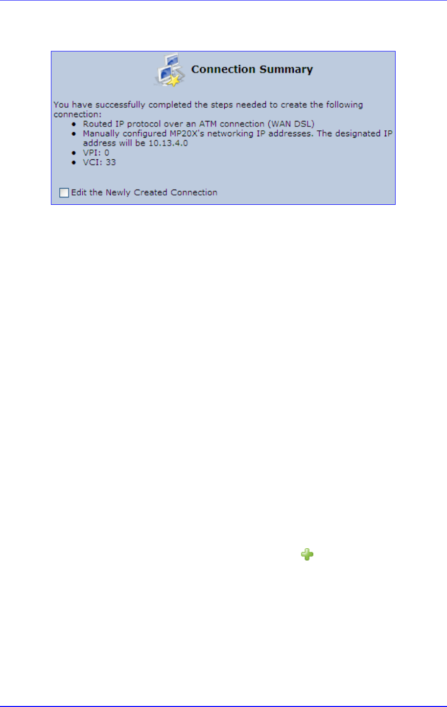
MP252 Multimedia Home Gateway 12. Network Connections
Version 3.4.0 143 June 2011
6. Click Next; the 'Connection Summary' screen appears:
Figure 12-18: Connection Summary Screen
7. Select the 'Edit the Newly Created Connection' check box if you want to perform
additional configurations after clicking Finish.
8. Click Finish to save the settings; the new connection is added to the ‘Network
Connections’ screen.
12.1.2 WAN Ethernet Connections
You can configure the following WAN Ethernet connection types:
MP252 connected to an external DSL modem and using PPPoE – see Section 12.1.2.1
on page 143
MP252 connected to an external Cable modem without authentication – see Section
12.1.2.2 on page 144
MP252 connected to an external Cable modem using PPTP – see Section 12.1.2.3 on
page 145
MP252 connected to an external Cable modem using L2TP – see Section 12.1.2.4 on
page 147
Automatic IP address using DHCP – see Section 12.1.2.5 on page 149
Manual IP address – see Section 12.1.2.6 on page 150
12.1.2.1 External DSL Modem using PPPoE
The procedure below describes how to configure an Internet connection using PPPoE when
MP252 is connected to an external DSL modem.
To create a PPPoE connection for external DSL modem:
1. In the 'Network Connections' screen, click the New icon; the 'Connection Wizard'
screen appears.
2. Select the Internet Connection option, and then click Next; the ‘Internet Connection’
screen appears.
3. Select the External DSL Modem option, and then click Next; the 'Point-To-Point
Protocol over Ethernet (PPPoE)' screen appears.
Figure 12-19: Point-to-Point Protocol over Ethernet (PPPoE) Screen
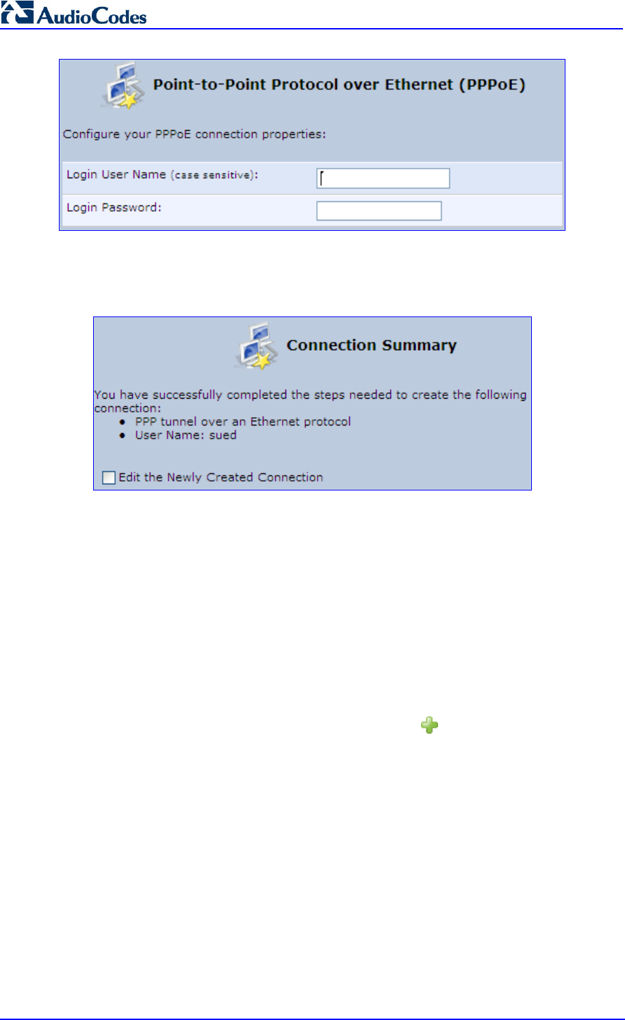
MP252 Multimedia Home Gateway 144 Document #: LTRT-23504
User's Manual
4. Enter the login PPPoE username and password.
5. Click Next; the screen 'Connection Summary' opens.
Figure 12-20: PPPoE Connection Summary
6. Select the 'Edit the Newly Created Connection' check box if you wish to be routed to the
new connection's configuration screen after clicking Finish.
7. Click Finish to save the settings; the new PPPoE connection is added to the ‘Network
Connections’ screen.
12.1.2.2 External Cable Modem without Authentication
The procedure below describes how to configure an Internet connection when MP252 is
connected to an external Cable modem and the ITSP does not require a username nor
password to connect.
To create an Ethernet connection for external Cable modem:
1. In the 'Network Connections' screen, click the New icon; the 'Connection Wizard'
screen appears.
2. Select the Internet Connection option, and then click Next; the ‘Internet Connection’
screen appears.
3. Select the External Cable Modem option, and then click Next; the ‘Internet Cable
Modem Connection' screen appears.
Figure 12-21: Internet Cable Modem Connection Screen
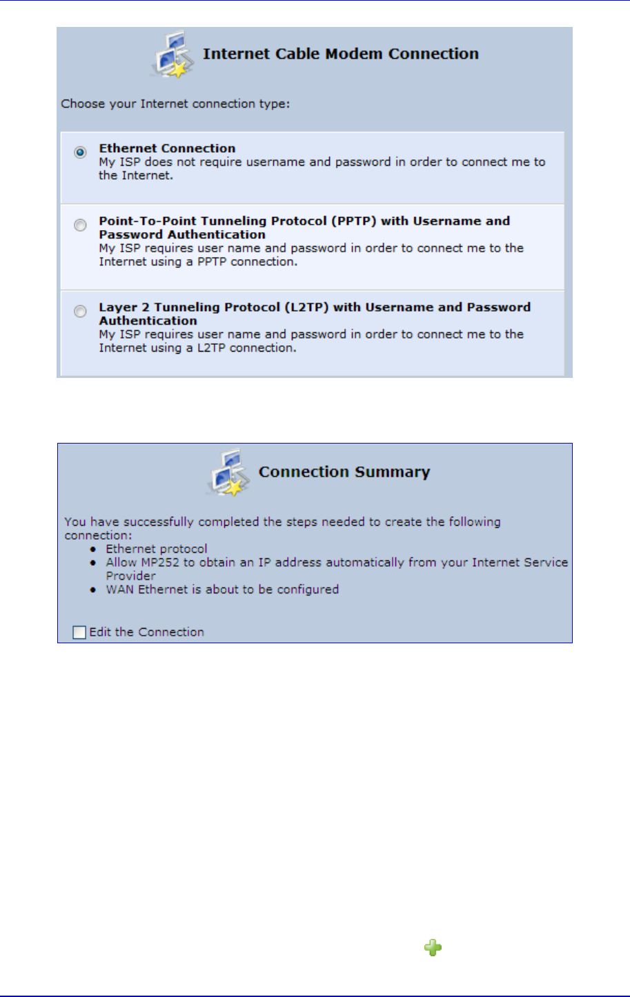
MP252 Multimedia Home Gateway 12. Network Connections
Version 3.4.0 145 June 2011
4. Select the Ethernet Connection option; the 'Connection Summary' screen appears.
Figure 12-22: Ethernet Connection Summary
5. Select the 'Edit the Connection' check box if you wish to be routed to the new
connection's configuration screen after clicking Finish.
6. Click Finish to save the settings; the new connection is added to the ‘Network
Connections’ screen.
12.1.2.3 External Cable Modem with PPTP
The procedure below describes how to configure an Internet connection when MP252 is
connected to an external Cable modem and using the PPTP protocol.
Point-to-Point Tunneling Protocol (PPTP) is a protocol developed by Microsoft targeted at
creating VPN connections over the Internet. This enables remote users to access MP252 via
any ISP that supports PPTP on its servers. PPTP encapsulates network traffic, encrypts
content using Microsoft's Point-to-Point Encryption (MPPE) protocol that is based on RC4,
and routes using the generic routing encapsulation (GRE) protocol.
To create PPTP for external Cable modem:
1. In the 'Network Connections' screen, click the New icon; the 'Connection Wizard'
screen appears.
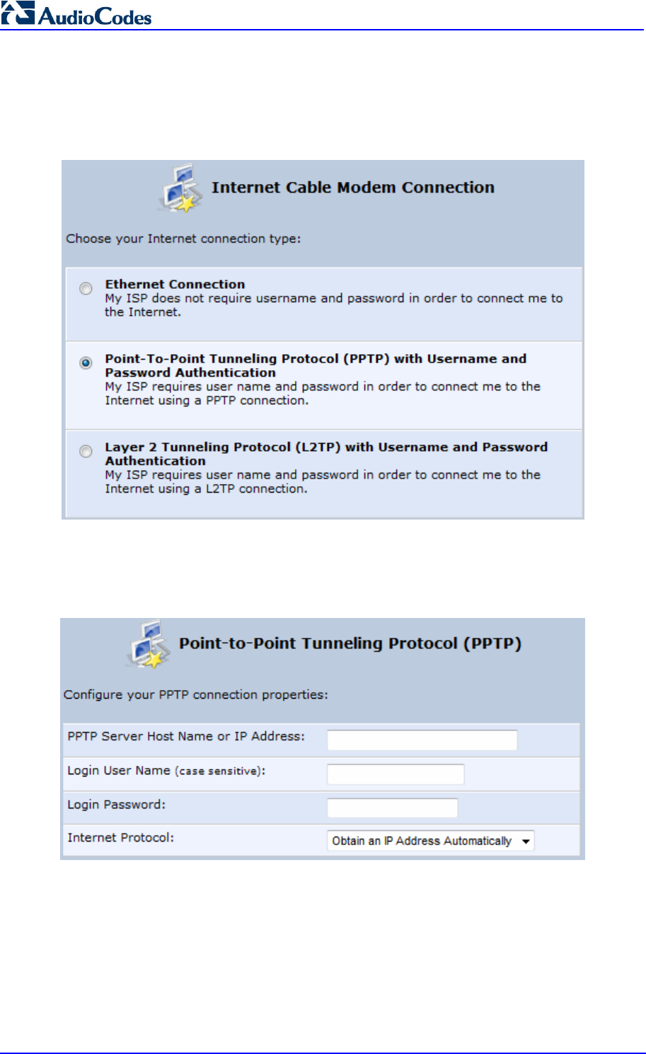
MP252 Multimedia Home Gateway 146 Document #: LTRT-23504
User's Manual
2. Select the Internet Connection option, and then click Next; the ‘Internet Connection’
screen appears.
3. Select the External Cable Modem option, and then click Next; the ‘Internet Cable
Modem Connection' screen appears.
Figure 12-23: Internet Cable Modem Connection Screen
4. Select the Point-To-Point Tunneling Protocol (PPTP) with Username and
Password Authentication option; the ‘Point-to-Point Tunneling Protocol (PPTP)'
screen appears.
Figure 12-24: Point-to-Point Tunneling Protocol (PPTP) Screen
5. Enter the PPTP server host name or IP address provided by your ITSP.
6. Enter the login user name and password provided by the administrator of the network
you are trying to access.
7. From the ‘Internet Protocol’ drop-down list, select whether the IP address is obtained
automatically or select ‘Use the Following IP Address’ and define the IP address.

MP252 Multimedia Home Gateway 12. Network Connections
Version 3.4.0 147 June 2011
8. Click Next; the screen 'Connection Summary' opens.
Figure 12-25: PPTP Connection Summary
9. Select the 'Edit the Newly Created Connection' check box if you wish to be routed to the
new connection's configuration screen after clicking Finish.
10. Click Finish to save the settings; the new connection is added to the ‘Network
Connections’ screen.
12.1.2.4 External Cable Modem with L2TP
You can connect MP252 to the Internet using an external cable modem where the
connection is L2TP. L2TP is an extension to the PPP protocol, enabling MP252 to create
VPN connections. Derived from Microsoft's PPTP and Cisco's Layer 2 Forwarding (L2F)
technology, L2TP encapsulates PPP frames into IP packets either at the remote user's PC or
at an ISP that has an L2TP Remote Access Concentrator (LAC). The LAC transmits the
L2TP packets over the network to the L2TP Network Server (LNS) at the corporate side
To create L2RP for external Cable modem:
1. In the 'Network Connections' screen, click the New icon; the 'Connection Wizard'
screen appears.
2. Select the Internet Connection option, and then click Next; the ‘Internet Connection’
screen appears.
3. Select the External Cable Modem option, and then click Next; the ‘Internet Cable
Modem Connection' screen appears.
Figure 12-26: Internet Cable Modem Connection Screen
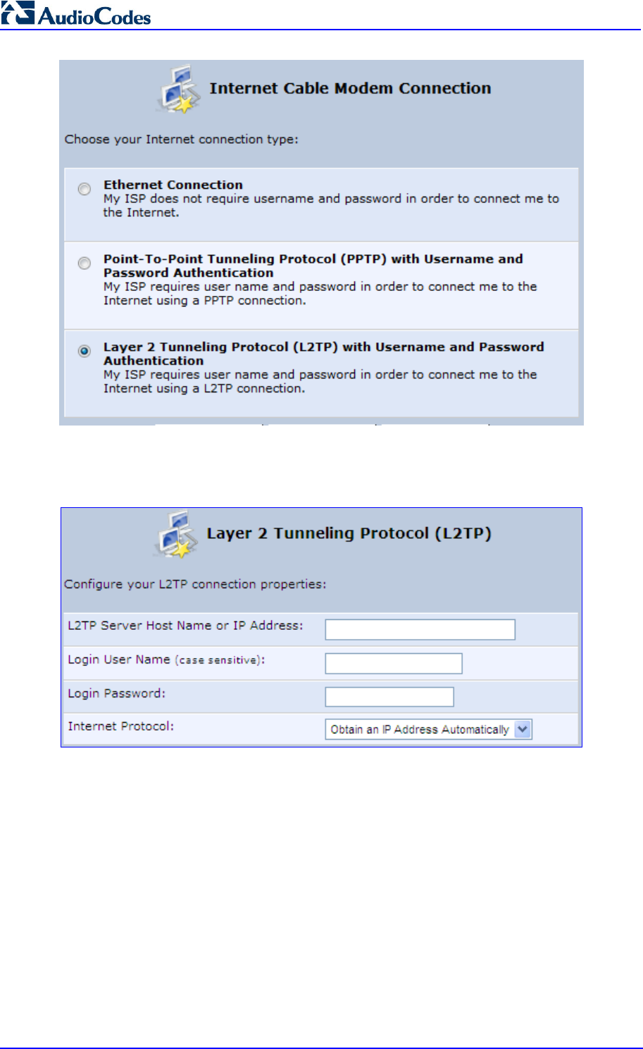
MP252 Multimedia Home Gateway 148 Document #: LTRT-23504
User's Manual
4. Select the Layer 2 Tunneling Protocol (L2TP) with Username and Password
Authentication option; the 'Layer 2 Tunneling Protocol (L2TP)' screen appears.
Figure 12-27: Layer 2 Tunneling Protocol (L2TP) Screen
5. Enter the L2TP server host name or IP address provided by your ITSP.
6. Enter the login user name and password provided by the administrator of the network
you are trying to access.
7. From the ‘Internet Protocol’ drop-down list, select whether the IP address is obtained
automatically or select ‘Use the Following IP Address’ and define the IP address.
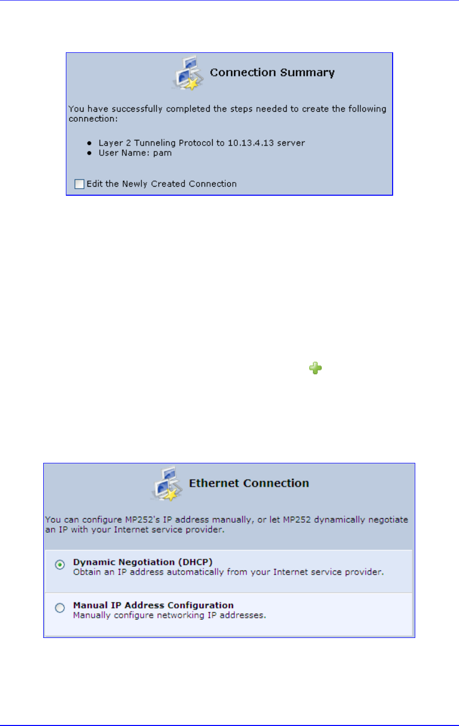
MP252 Multimedia Home Gateway 12. Network Connections
Version 3.4.0 149 June 2011
8. Click Next; the screen 'Connection Summary' opens.
Figure 12-28: L2TP Connection Summary
9. Select the 'Edit the Newly Created Connection' check box if you wish to be routed to the
new connection's configuration screen after clicking Finish.
10. Click Finish to save the settings; the new connection is added to the ‘Network
Connections’ screen.
12.1.2.5 DHCP
The Dynamic Host Configuration Protocol (DHCP) connection for the physical WAN Ethernet,
allows MP252 to obtain an IP address automatically from the service provider when
connecting to the Internet.
To create a DHCP connection:
1. In the 'Network Connections' screen, click the New icon; the 'Connection Wizard'
screen appears.
2. Select the Internet Connection option, and then click Next; the ‘Internet Connection’
screen appears.
3. Select the Ethernet Connection option, and then click Next; the ‘Ethernet Connection'
screen appears.
Figure 12-29: Ethernet Connection Screen
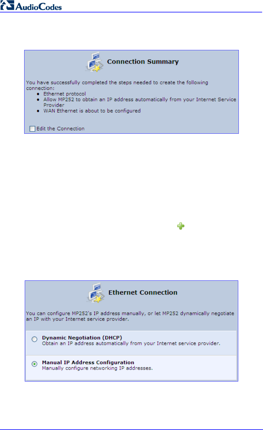
MP252 Multimedia Home Gateway 150 Document #: LTRT-23504
User's Manual
4. Select the Dynamic Negotiation (DHCP) option, and then click Next; the screen
'Connection Summary' opens.
Figure 12-30: DHCP Connection Summary
5. Select the 'Edit the Connection' check box if you wish to be routed to the new
connection's configuration screen after clicking Finish.
6. Click Finish to save the settings; the new connection is added to the ‘Network
Connections’ screen.
12.1.2.6 Manual IP Address
The Manual IP Address feature is used to manually configure the networking IP addresses
when connecting to the Internet.
To manually configure the IP address:
1. In the 'Network Connections' screen, click the New icon; the 'Connection Wizard'
screen appears.
2. Select the Internet Connection option, and then click Next; the ‘Internet Connection’
screen appears.
3. Select the Ethernet Connection option, and then click Next; the ‘Ethernet Connection'
screen appears.
Figure 12-31: Ethernet Connection Screen
4. Select the Manual IP Address Configuration option, and then click Next; the screen
‘Manual IP Address Configuration’ opens.
Figure 12-32: Manual IP Address Configuration Screen
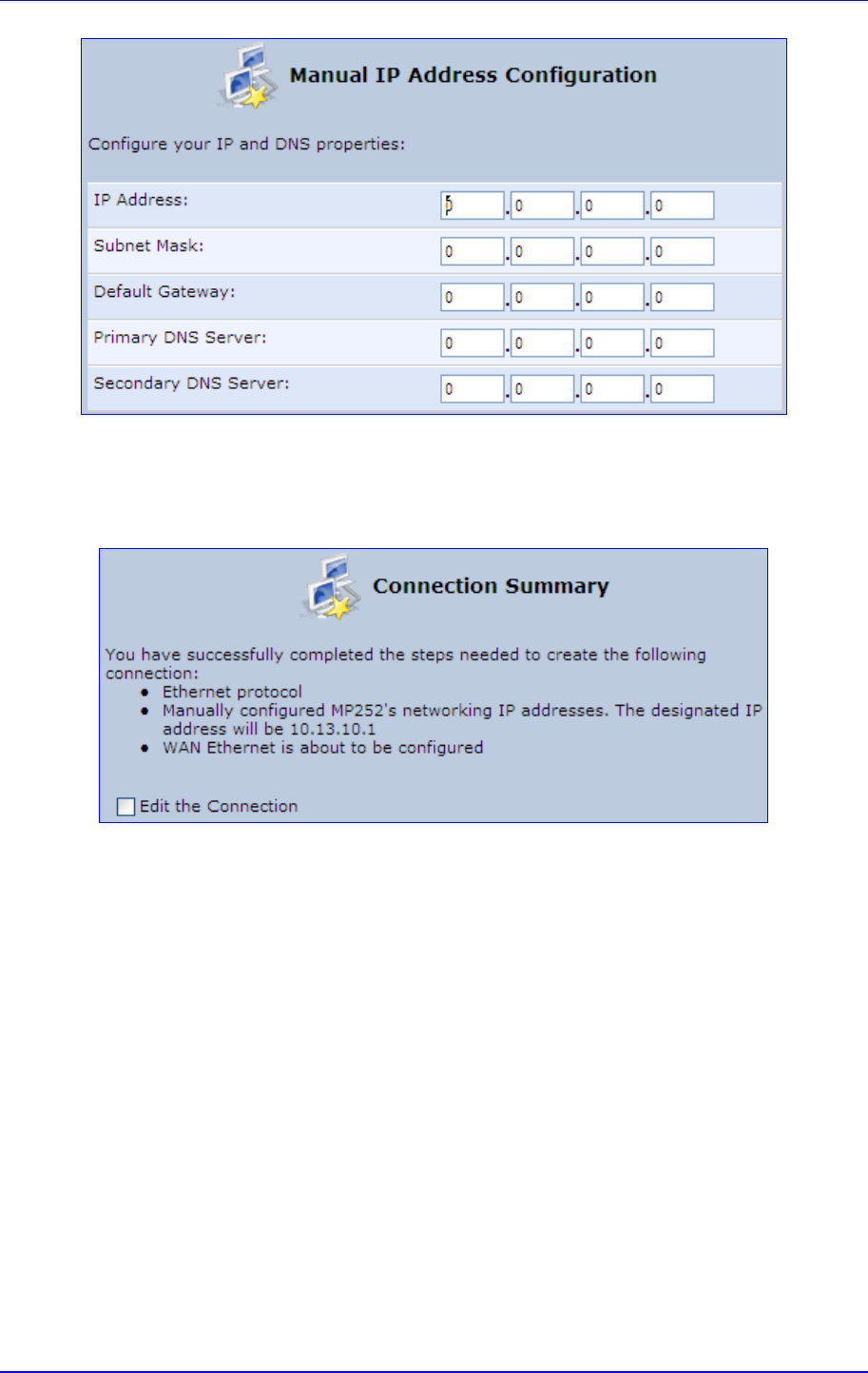
MP252 Multimedia Home Gateway 12. Network Connections
Version 3.4.0 151 June 2011
5. Configure the IP address and other network parameters, and then click Next; Select the
Manual IP Address Configuration option, and then click Next; the 'Connection
Summary' screen appears.
Figure 12-33: Manual IP Connection Summary
6. Select the 'Edit the Connection' check box if you wish to be routed to the new
connection's configuration screen after clicking Finish.
7. Click Finish to save the settings; the new connection is added to the ‘Network
Connections’ screen.
12.2 LAN Connection
This section describes how to configure the following MP252 LAN connections:
Wireless LAN
LAN hardware Ethernet switch
12.2.1 Wireless LAN
This section describes how to configure the MP252 wireless network. This network is
configured in the ‘Network Connections’ screen, which provides a connection wizard that
guides you through the network configuration stages.
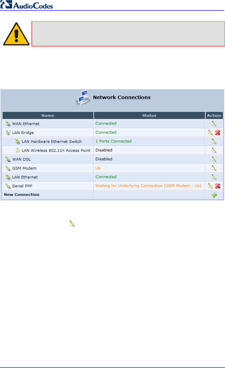
MP252 Multimedia Home Gateway 152 Document #: LTRT-23504
User's Manual
Note: To establish a wireless network connection between a PC and the MP252, you
must also configure the PC for wireless connectivity (see Section 6.2 on page
61).
To configure the Wireless LAN:
1. From the menu bar, click the Network Connections menu; the 'Network Connections'
screen appears.
Figure 12-34: Network Connections Screen Displaying LAN Wireless Interface
The 'Status' column corresponding to the wireless LAN network (‘LAN Wireless 802.11n
Access Point’) displays whether the wireless connection is enabled or disabled.
2. Click the Edit icon corresponding to the 'LAN Wireless 802.11n Access Point'
network name; the 'LAN Wireless 802.11n Access Point Properties' screen appears,
displaying the contents of the General tab.
Figure 12-35: LAN Wireless 802.11n Access Point Properties (General Tab) Screen
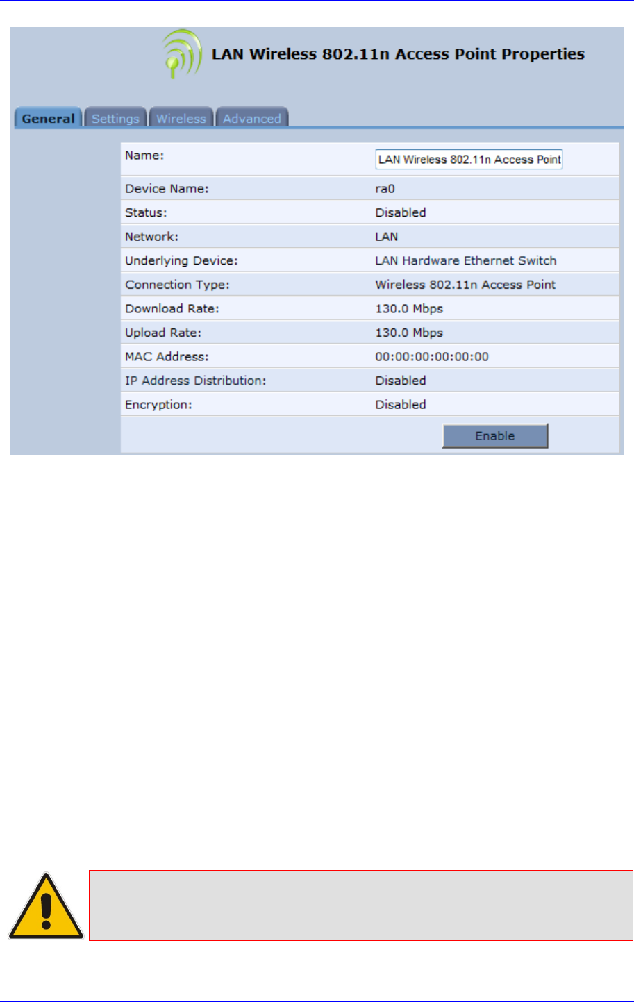
MP252 Multimedia Home Gateway 12. Network Connections
Version 3.4.0 153 June 2011
3. In the ‘Name’ field, enter an arbitrary name for your wireless network.
The General tab also allows you to enable or disable the wireless connection (for more
information, see Section 12.2.1.1 on page 153). In addition, it displays various statistics such
as download and upload rate, and whether encryption is enabled or disabled. These
parameters can be configured using the other tabs, as described in the subsequent sections.
12.2.1.1 Enabling and Disabling the Wireless Network
Once you have configured your MP252 wireless network connection, you can enable and
disable it, as required.
To enable or disable the wireless network, do one of the following:
Press the WiFi button located on the front panel of the MP252 (see Section 3.1.1 on
page 27)
In the ‘LAN Wireless 802.11n Access Point Properties (General Tab)’ screen (see
Section Figure 12-35 on page 152), click the Enable or Disable button.
12.2.1.2 Configuring Wireless Properties under the Settings Tab
The procedure below describes the configurations under the Settings tab of the ‘LAN
Wireless 802.11 Access Point Properties’ screen.
Note: Since your MP252 wireless network is configured to operate with default
settings, it is recommended to leave the settings in this screen at their default
values.
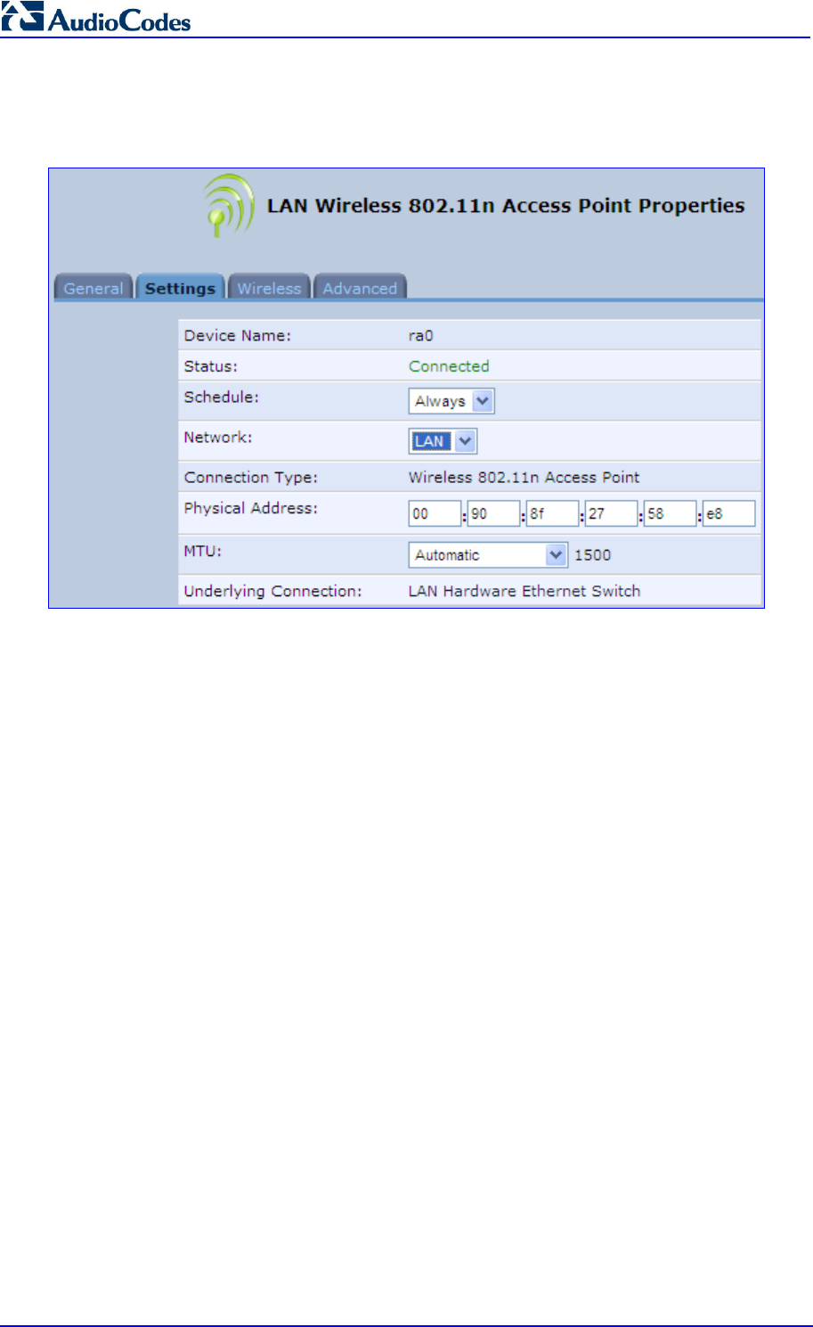
MP252 Multimedia Home Gateway 154 Document #: LTRT-23504
User's Manual
To configure the wireless parameters under the Settings tab:
1. Click the Settings tab.
Figure 12-36: LAN Wireless 802.11 Access Point Properties (Settings Tab) Screen
The ‘Underlying Connection’ read-only field displays the underlying connection upon
which the wireless LAN is defined.
2. From the ‘Scheduler’ drop-down list, select the Scheduler rule during which this network
connection is active. To ensure that the network is always active, select ‘Always’. To
define Scheduler rules, see Section 4.5.1 on page 47.
3. From the ‘Network’ drop-down list, select the network (LAN, WAN, or DMZ) to which this
new network is related.
4. In the ‘Physical Address’ field, define the physical address of the network card used for
your network.
5. From the ‘MTU’ drop-down list, select the largest packet size permitted for Internet
transmission (i.e., MTU / Maximum Transmission Unit). By default, it is set to 'Automatic',
whereby MP252 selects the best MTU for your Internet connection. If you modify this
field, ensure that the range is 1200 to 1500.
6. Click OK to save your settings.
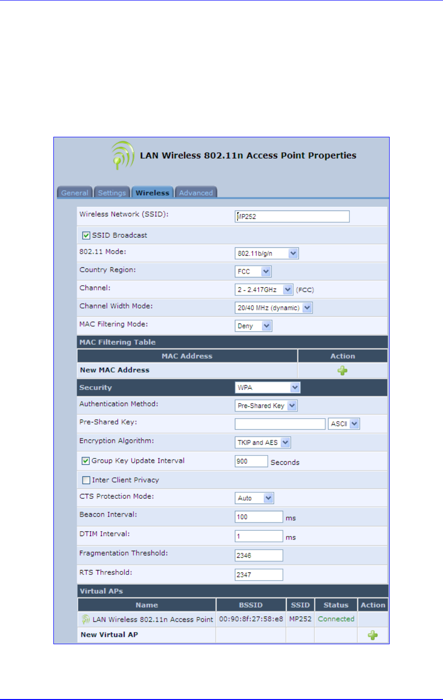
MP252 Multimedia Home Gateway 12. Network Connections
Version 3.4.0 155 June 2011
12.2.1.3 Configuring Wireless Properties under the Wireless Tab
The procedure below describes the configurations under the Wireless tab of the ‘LAN
Wireless 802.11 Access Point Properties’ screen.
To configure the wireless parameters under the Wireless tab:
1. Click the Wireless tab.
Figure 12-37: LAN Wireless 802.11 Access Point Properties (Wireless Tab) Screen
2. Refer to the subsequent sections for a description of the parameters in this screen.

MP252 Multimedia Home Gateway 156 Document #: LTRT-23504
User's Manual
12.2.1.3.1 Wireless Network Group
This group in the Wireless tab screen configures the basic wireless access point settings.
Figure 12-38: Wireless Network Group in Wireless Tab Screen
The table below describes the parameters in this group:
Table 12-1: Wireless Tab – Basic Wireless Access Point Parameters Description
Parameter Description
Wireless Network
(SSID)
Enter the name of the wireless network. This name is needed for a wireless
device to attach to your wireless network (see Section 6.2 on page 61).
Note: The default wireless (Wi-Fi) network name (SSID) is “MP252” (and is
unsecured).
SSID Broadcast
Select this check box to enable the SSID's broadcast. SSID broadcast is used to
hide the name of the AP (SSID) from clients.
802.11 Mode
Select the wireless communication standard that is compatible with your client's
wireless card: 802.11b/g Mixed, 802.11g Only, 802.11b Only, 802.11b/g/n,
802.11g/n, 802.11n Only.
Country Region Select the Wi-Fi country region for allowing only permitted channels
(frequencies) for the region.
Note: This parameter determines the available channel options listed in the
‘Channel’ parameter.
Channel Select the appropriate channel to correspond with your network settings. All
devices in your wireless network must broadcast on different channels to
function correctly.
Note: The available channels depend on the country region (configured by the
‘Country Region’ parameter) in which you are operating MP252. For example, if
you selected ‘FCC’ as the country region, the available channels from which you
can select conform to the U.S.A. Regulatory Authority FCC (Federal
Communications Commission).
Channel Width
Mode
Select the available transmit data rate of the wireless network: 20 MHz only or
20/40 MHz dynamic.
Virtual APS
Virtual APS You can set up multiple virtual wireless LAN's on MP252. Such virtual wireless
LANs are referred to as "Virtual APs" (virtual access points). For a detailed
description on configuring Virtual APS, see 'Virtual Access Points' on page 162.
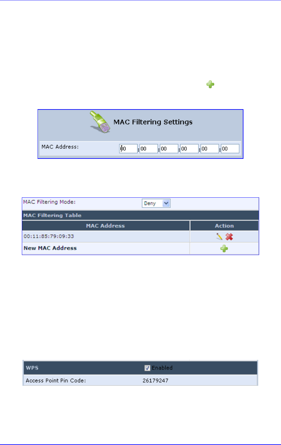
MP252 Multimedia Home Gateway 12. Network Connections
Version 3.4.0 157 June 2011
12.2.1.3.2 Configuring MAC Filtering
The procedure below describes how to filter wireless users according to their MAC
addresses. You can define as list of MAC addresses and for the entire list, either allow or
deny access.
To define MAC filtering:
1. From the 'MAC Filtering Mode' drop-down list, select either 'Allow' or 'Deny' (or ‘Disable’
if you do not want use MAC filtering).
2. In the MAC Filtering Table, click the New MAC Address icon; the 'MAC Filtering
Settings' screen appears.
Figure 12-39: MAC Filtering Settings Screen
3. In the 'MAC Address' field, enter the MAC address to be filtered.
4. Click OK; the MAC address is listed in the MAC Filtering table.
Figure 12-40: MAC Address Added to MAC Filtering Table
12.2.1.3.3 Enabling Wi-Fi Protected Setup (WPS)
The procedure below describes how to enable WPS. WPS is a method for simplifying the
security setup and management of wireless networks. This feature is disabled by default. By
enabling it, you can control the setup of your wireless security, which is defined in the
Security group.
To enable WPS:
Under the WPS group, select ‘Enabled’; an access point pin code is automatically
generated and displayed.
Figure 12-41: WPS Group in Wireless Tab Screen
The access point pin code is an eight digit pin number, provided by the wireless client's
software. When attempting to connect a wireless client to MP252, you must be aware of its
setup method.
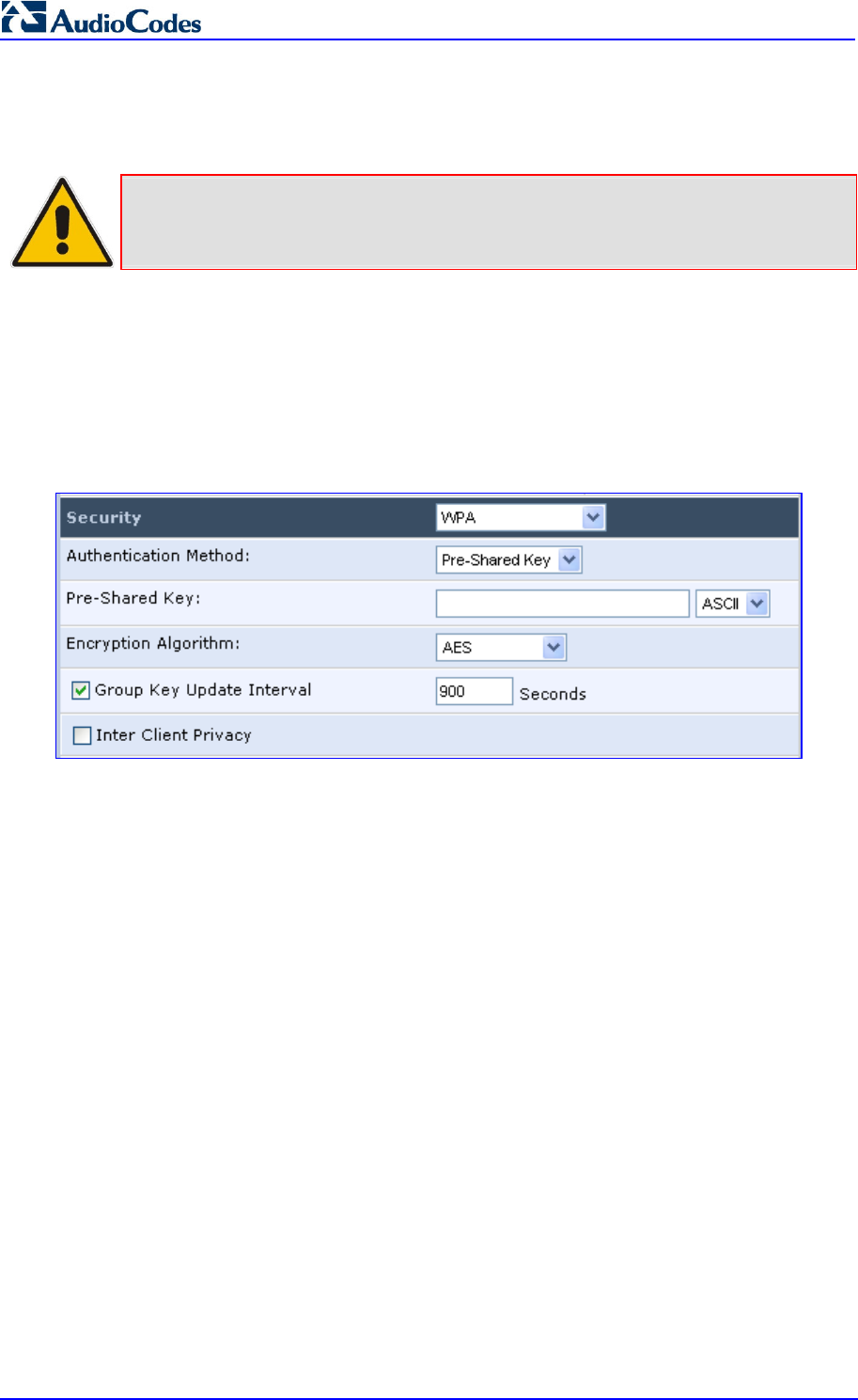
MP252 Multimedia Home Gateway 158 Document #: LTRT-23504
User's Manual
12.2.1.3.4 Configuring Wireless Security
The procedure below describes how to configure wireless security.
Note: WPS supports only the WPA security protocol. Therefore, when enabled (see
Section 12.2.1.3.3 on page 157), only the WPA protocols are available (in the
‘Security’ drop-down list described below).
To define wireless security:
1. From the 'Security' drop-down list, select the type of security protocol; the screen
refreshes, displaying parameters relevant to the selected protocol:
• None: disables security on your wireless connection.
• WPA: WPA is a data encryption method for 802.11 wireless LANs.
Figure 12-42: Configuring WPA Security
Configure the following fields:
b. Authentication Method: select the required authentication method
('Pre-Shared Key' and '802.1x').
c. Pre-Shared Key: this field appears only if you selected ‘Pre-Shared Key’ in
the ‘Authentication Method field. Enter your encryption key (using either an
ASCII or a Hex value), by selecting the value type in the drop-down list
provided.
d. Encryption Algorithm: select 'TKIP' (Temporal Key Integrity Protocol), 'AES'
(Advanced Encryption Standard) or both ('TKIP and AES') for the encryption
algorithm.
e. Group Key Update Interval: select this check box, and then enter the time
interval in seconds for updating a group key.
f. Inter Client Privacy: select this check box to prevent communication
between the wireless network clients using the same access point. When
enable, clients are unable to view and access each other's shared directories.
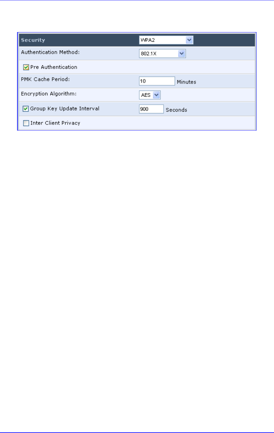
MP252 Multimedia Home Gateway 12. Network Connections
Version 3.4.0 159 June 2011
• WPA2: WPA2 is an enhanced version of WPA, and defines the 802.11i protocol.
Figure 12-43: Configuring WPA2 Security
a. Authentication Method: select the authentication method ('Pre-Shared Key'
and '802.1x').
b. Pre-Shared Key: this field appears only if you selected this authentication
method. Enter your encryption key in either an ASCII or a Hex value (by
selecting the value type in the drop-down list provided).
c. Pre Authentication: This field appears only when selecting the 802.1x
authentication method. Select this option to enable MP252 to accept RADIUS
authentication requests from computers connected to other access points.
This enables roaming from one wireless network to another.
d. PMK Cache Period: This field appears only when selecting the 802.1x
authentication method. This field defines the number of minutes before
deletion (and renewal) of the Pairwise Master Key used for authentication.
e. Encryption Algorithm: encryption algorithm for WPA2 is the Advanced
Encryption Standard (AES).
f. Group Key Update Interval: Defines the time interval in seconds for updating
a group key.
g. Inter Client Privacy: select the check box to prevent communication between
the wireless network clients using the same access point. Clients will not be
able to view and access each other's shared directories.
• WPA and WPA2: WPA and WPA2 is a mixed data encryption method. For a
description of these fields, see WPA and WPA2 above.
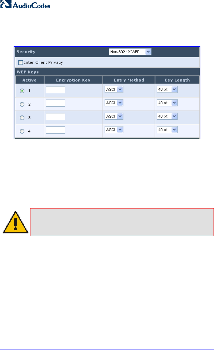
MP252 Multimedia Home Gateway 160 Document #: LTRT-23504
User's Manual
• Non-802.1x WEP: data encryption method utilizing a statically defined key for
wireless clients that do not use 802.1x for authentication, but use WEP for
encryption. You may define up to four keys, but use only one at a time.
Figure 12-44: Configuring Non-WEP Security
a. Inter Client Privacy: select this check box to prevent communication
between the wireless network clients using the same access point. Clients will
not be able to view and access each other's shared directories.
b. WEP Keys table:
Active: select the encryption key to be activated.
Encryption Key: enter the encryption key until the entire field is filled.
The key cannot be shorter than the field's length.
Entry Method: select the character type for the key: ASCII or HEX.
Key Length: select the key length in bits: 40 or 104 bits.
Note: The encryption key must be defined in the wireless Windows client as well. This
is done in the Connection Properties Configuration window (your encryption key
is entered in both the 'Network key' and 'Confirm network key' fields, as shown in
the figure below.
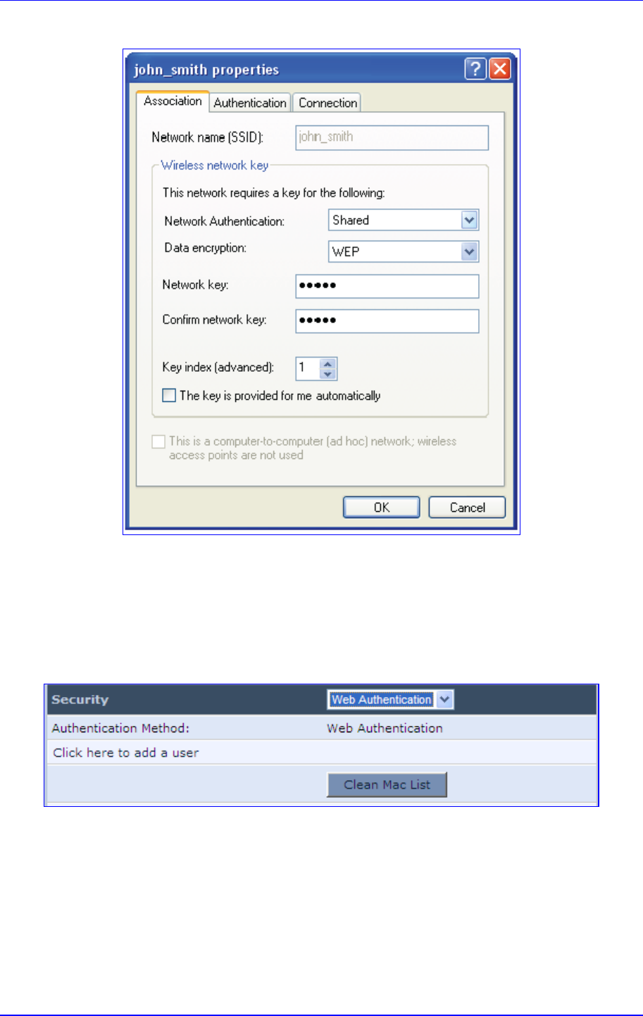
MP252 Multimedia Home Gateway 12. Network Connections
Version 3.4.0 161 June 2011
Figure 12-45: Configuring Encryption Key in Windows Wireless Client
• Web Authentication: wireless clients attempting to connect to the wireless
connection (Internet) receive a Web Authentication screen, requiring the clients to
authenticate themselves before they are able to use the connection. To add a Web
client user, click the Click here to add a user link. MP252 keeps record of
authenticated clients. To clear this list, click the Clean Mac List button. Clients
need to re-authenticate themselves to use the wireless connection.
Figure 12-46: Configuring Authentication Only Security
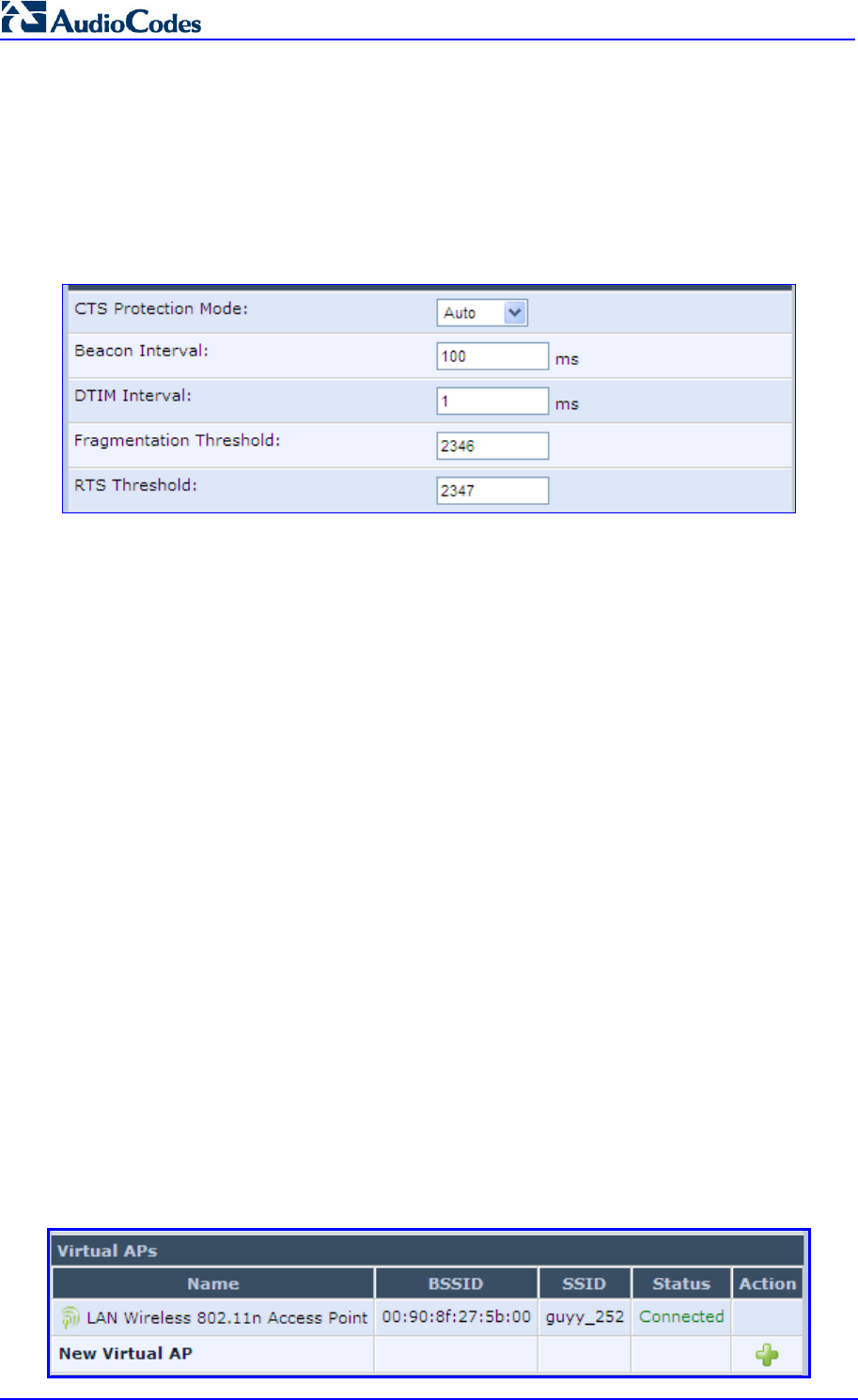
MP252 Multimedia Home Gateway 162 Document #: LTRT-23504
User's Manual
12.2.1.3.5 Configuring Transmission Properties
The procedure below describes how to configure wireless transmission properties.
To configure the transmission properties:
1. Access the Wireless tab screen.
Figure 12-47: Transmission Parameters in Wireless Tab Screen
2. From the ‘CTS Protection Mode’ drop-down list, select whether you want to enable or
disable this feature (‘Always' to enable CTS or 'Auto' to have MP252 automatically
decide whether or not to use this feature). CTS Protection Mode boosts your MP252's
ability to intercept 802.11g and 802.11b transmissions. Conversely, CTS Protection
Mode decreases performance. Leave this feature disabled unless you encounter
severe communication difficulties between MP252 and 802.11g products.
3. In the ‘Beacon Interval’ field, enter how often the beacon packet is sent. A beacon is a
packet broadcast by MP252 to synchronize the wireless network.
4. In the ‘DTIM Interval’ field, enter the Delivery Traffic Indication Message (DTIM)
countdown value that informs wireless clients of the next opportunity to receive
multicast and broadcast messages. This value ranges between 1 and 16384.
5. In the ‘Fragmentation Threshold’ field, enter the packet size threshold above which
packets are fragmented into multiple packets. Try to increase the fragmentation
threshold if you encounter high packet error rates. Do not set the threshold too low,
since this can result in reduced networking performance.
6. In the ‘RTS Threshold’ field, enter the packet threshold size below which the Request to
Send (RTS) / Clear to Send (CTS) mechanism are not active. MP252 sends RTS
packets to the wireless client to negotiate the dispatching of data. The wireless client
responds with a CTS packet, signaling that transmission can commence. If you
encounter inconsistent data flow, try a slight reduction in the RTS threshold size.
12.2.1.3.6 Adding Virtual Access Points
You can set up multiple virtual wireless LAN's on MP252, limited. Such virtual wireless LANs
are referred to as "Virtual APs" (virtual access points). In the Wireless tab's screen, under
the section 'Virtual APs' section, MP252's physical wireless access point is displayed first,
and on top of which virtual connections may be created.
Figure 12-48: Virtual APs Table
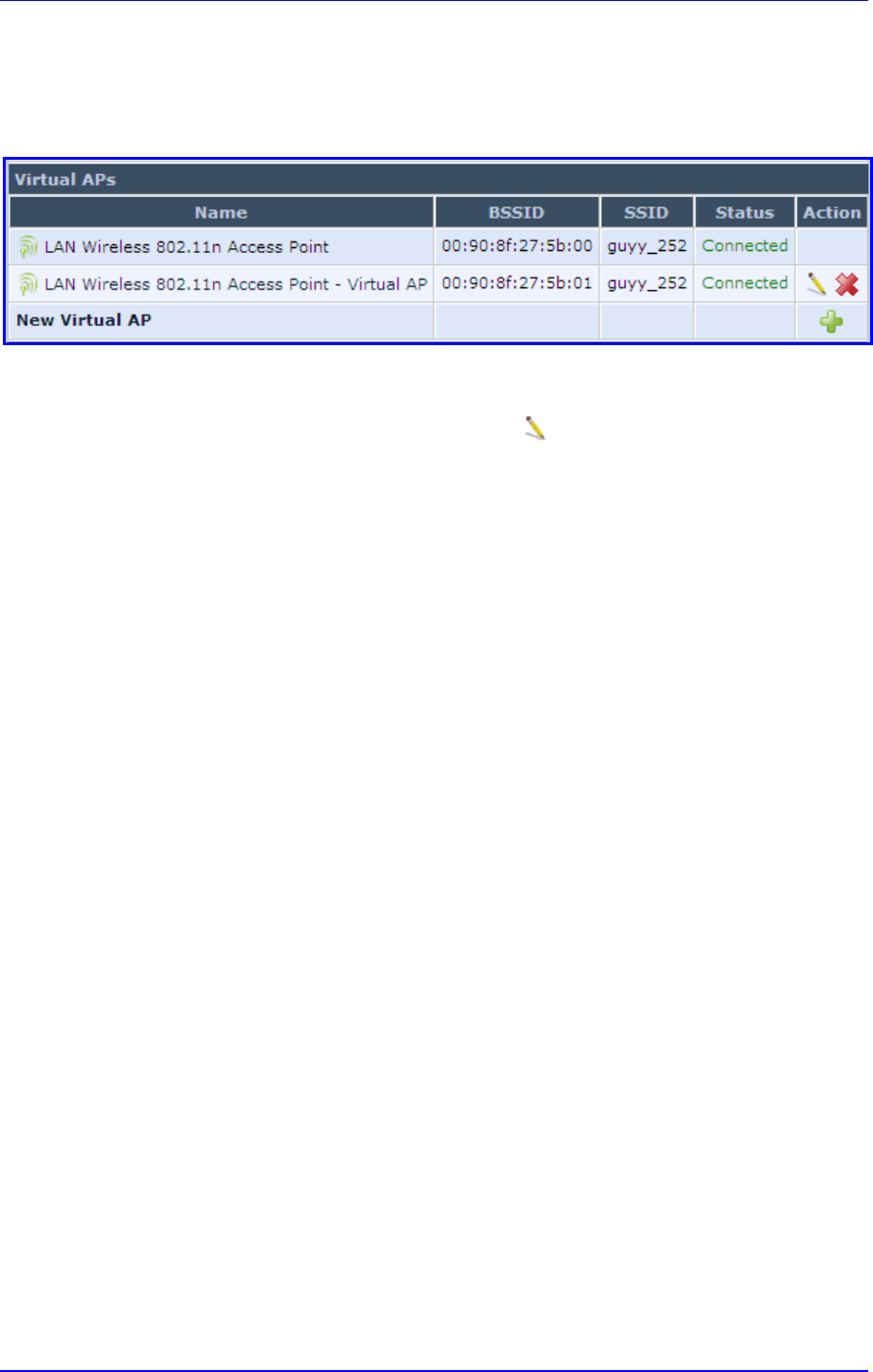
MP252 Multimedia Home Gateway 12. Network Connections
Version 3.4.0 163 June 2011
To create a virtual connection:
1. In the Wireless tab's screen, under the section 'Virtual APs' section, click the New
Virtual AP link; the screen refreshes, displaying the new virtual connection.
Figure 12-49: New Virtual AP
The new virtual connection is also added to the list of connections in the 'Network
Connections' screen (Network Connections menu), and is configurable like any other
connection (by clicking its corresponding Edit icon).
A useful implementation of Virtual AP's is to define a virtual connection with a different SSID
value to dedicate it for guest access. Through this connection, guests are able to access the
WAN, but they are denied access to other wireless LANs provided by MP252. To do so,
perform the following:
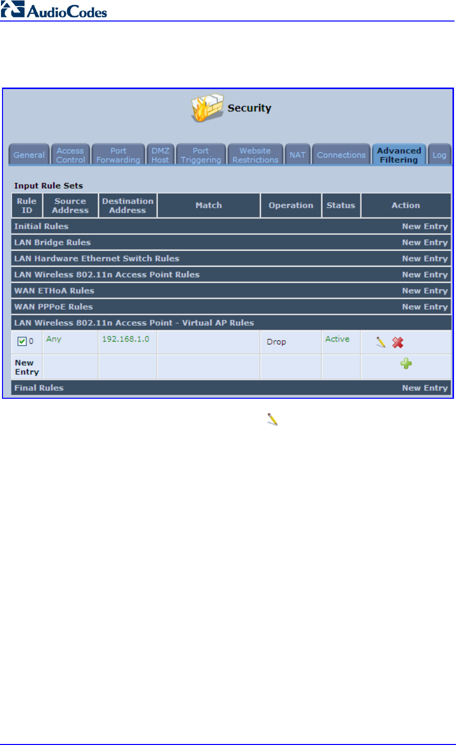
MP252 Multimedia Home Gateway 164 Document #: LTRT-23504
User's Manual
2. Set a firewall rule that blocks access to all other MP252 LANs (Security menu >
Advanced Filtering tab).
Figure 12-50: Firewall Blocking Access to All Other LANs
3. In the Wireless tab's screen, click the Edit icon corresponding to the Virtual AP to
open the virtual connection's 'LAN Wireless 802.11n Access Point - Virtual AP
Properties' screen:
a. In the 'Internet Protocol' section under the 'Settings' sub-tab, enter an IP address
for the connection by selecting 'Use the Following IP Address'.
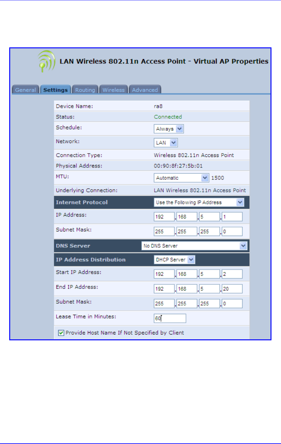
MP252 Multimedia Home Gateway 12. Network Connections
Version 3.4.0 165 June 2011
b. In the 'IP Address Distribution' section, select 'DHCP Server' and enter the IP
range from which IP addresses will be granted to wireless guests.
c. Click OK.
Figure 12-51: Example Virtual AP
After performing this procedure, you have secured all of your wireless connections. A guest
is only able to connect to the "Guests" wireless LAN, from which only the WAN access is
granted.
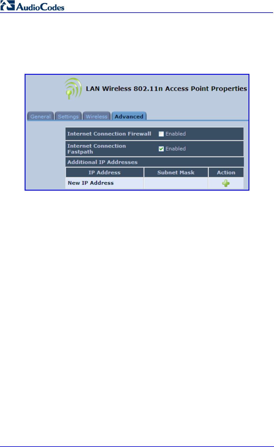
MP252 Multimedia Home Gateway 166 Document #: LTRT-23504
User's Manual
12.2.1.4 Advanced Tab
The Advanced tab allows you to enable your firewall on your wireless network connection as
well as define alias names.
Figure 12-52: Wireless Advanced Tab
Internet Connection Firewall: Your MP252's firewall helps protect your computer by
preventing unauthorized users from gaining access to it through a network such as the
Internet. The firewall can be activated per network connection. To enable the firewall on
this network connection, select the 'Enabled' check box.
Internet Connection Fastpath: Select this check box to utilize the Fastpath algorithm
for enhancing packet flow, resulting in faster communication between the LAN and the
WAN
Additional IP Addresses: You can add alias names (additional IP addresses) to
MP252 by clicking the New IP Address link. This enables you to access MP252 using
these aliases in addition to the IP address (e.g., 192.168.2.1) and http://mp252.home.
12.2.2 LAN Hardware Ethernet Switch
The LAN Hardware Ethernet Switch interface represents the physical ports on MP252.
To configure the LAN hardware Ethernet switch:
4. From the menu bar, click the Network Connections menu; the 'Network Connections'
screen appears.
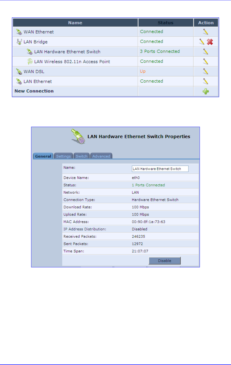
MP252 Multimedia Home Gateway 12. Network Connections
Version 3.4.0 167 June 2011
Figure 12-53: Network Connections Screen
5. Click the LAN Hardware Ethernet Switch link; the LAN Hardware Ethernet Switch
Properties screen appears:
Figure 12-54: LAN Hardware Ethernet Switch Screen
6. The General tab allows you to assign a name to this connection as well as disable or
enable the connection, by clicking the Enable or Disable buttons respectively.
12.2.2.1 Settings Tab
The Settings tab screen is displayed below:
Figure 12-55: LAN Hardware Ethernet Switch Screen – Settings Tab
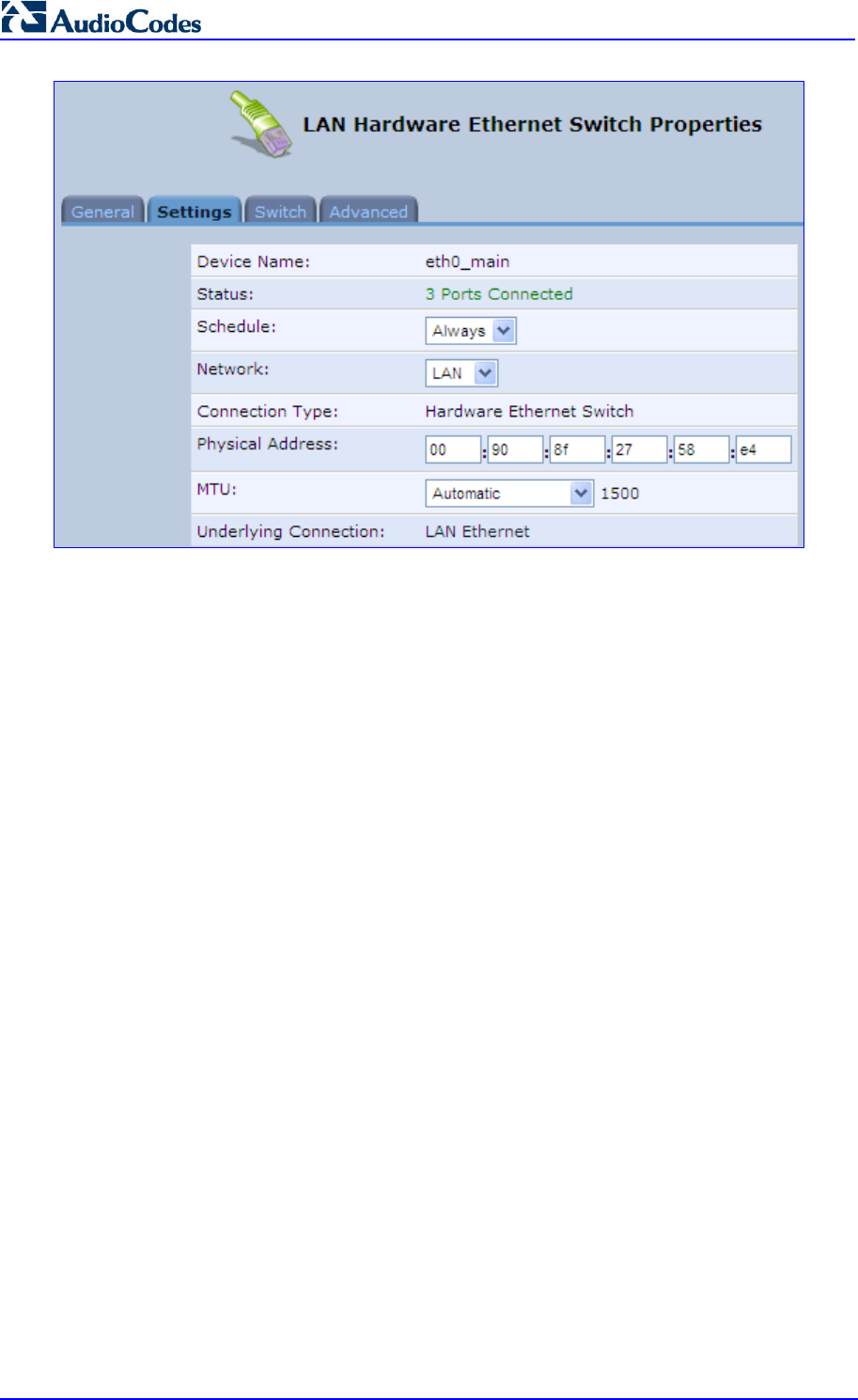
MP252 Multimedia Home Gateway 168 Document #: LTRT-23504
User's Manual
The Settings tab provides you with the following parameters
Schedule: By default, the connection is always active. However, you can configure
scheduler rules to define time segments during which the connection is active. Once a
scheduler rule(s) is defined, the drop-down list allows you to choose between the
available rules.
Network: Select whether the parameters you are configuring relate to a WAN, LAN or
DMZ connection.
Physical Address: The physical address of the network card used for your network.
Some cards allow you to change this address.
MTU: Maximum Transmission Unit. It specifies the largest packet size permitted for
Internet transmission. In the default setting, Automatic, the gateway selects the best
MTU for your Internet connection. Select 'Automatic by DHCP' to have the DHCP
determine the MTU. In case you select 'Manual' it is recommended to enter a value in
the 1200 to 1500 range.
12.2.2.2 Switch Tab
The Switch tab screen is displayed below:
Figure 12-56: LAN Hardware Ethernet Switch Screen – Switch Tab
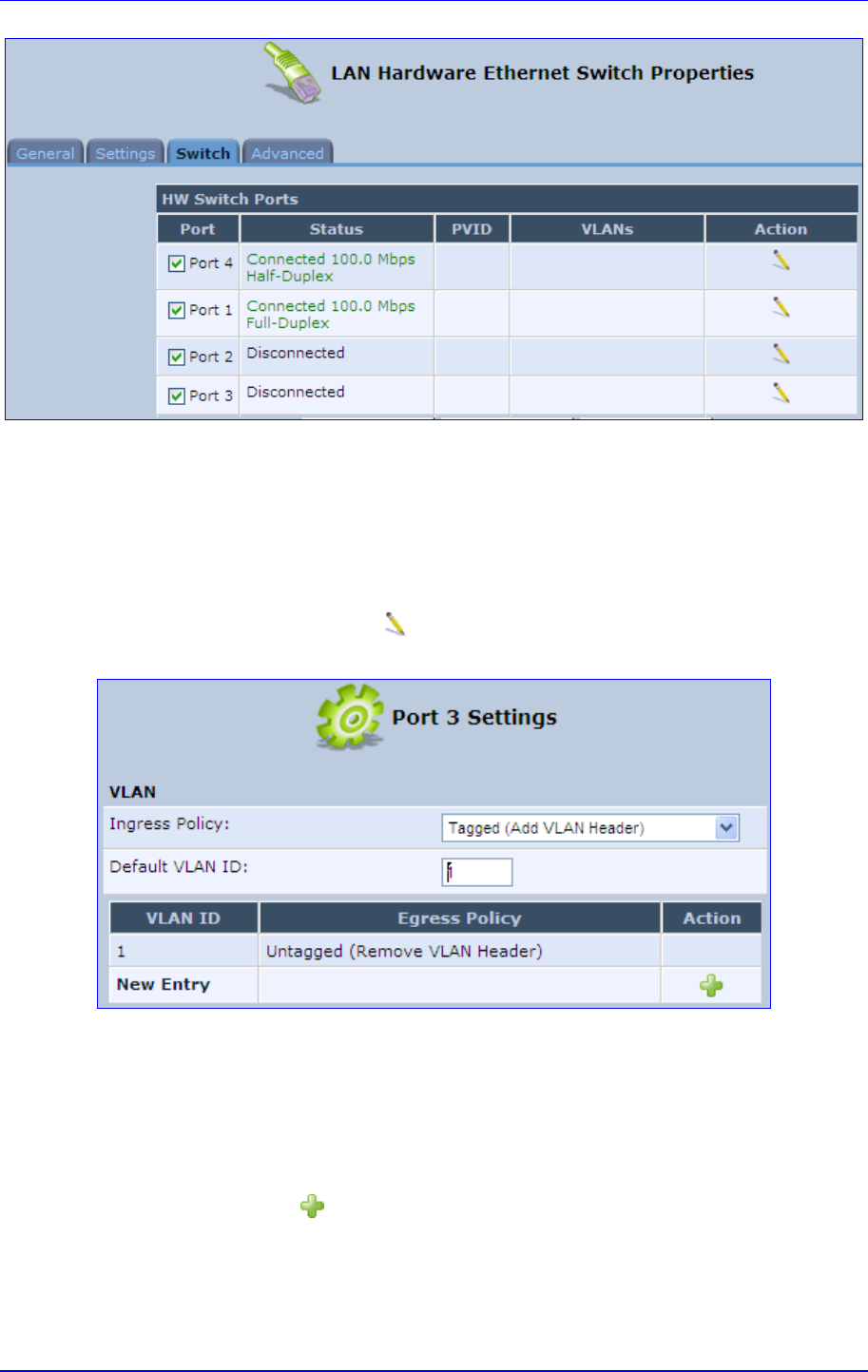
MP252 Multimedia Home Gateway 12. Network Connections
Version 3.4.0 169 June 2011
The Switch tab screen displays the hardware switch ports properties. The switch ports are
physical sockets on the MP252 to which different cables connect. The table in this screen
consists of a list of all available ports, their status, and the VLANs of which they are members.
Untagged packets (packets without a VLAN tag) that arrive at a port are tagged with the
VLAN number that appears under the Port VLAN Identifier (‘PVID’) column.
To edit the configuration of a port:
1. Click a connected port's Edit icon.
Figure 12-57: Port Settings Screen
2. Ingress (incoming packets):
a. From the ‘Ingress Policy’ drop-down list, select whether or not to tag incoming
packets with the port's VLAN header.
b. If the 'Tagged (Add VLAN Header)' option is selected, in the ‘Default VLAN ID’ field,
enter the port's VLAN identifier.
3. Egress (outgoing packets):
a. Click the New icon; the Add Port to a VLAN screen appears.
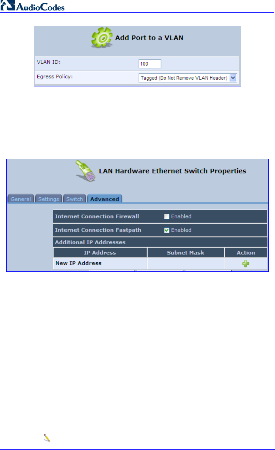
MP252 Multimedia Home Gateway 170 Document #: LTRT-23504
User's Manual
b. In the ‘VLAN ID’ field, enter the VLAN ID for this port.
c. From the ‘Egress Policy’ drop-down list, select whether or not to remove the VLAN
tag from outgoing packets.
12.2.2.3 Advanced Tab
The Advanced tab screen is displayed below:
Figure 12-58: LAN Hardware Ethernet Switch Screen – Advanced Tab
Internet Connection Firewall: Your gateway's firewall helps protect your computer by
preventing unauthorized users from gaining access to it through a network such as the
Internet. The firewall can be activated per network connection. To enable the firewall on
this network connection, select the 'Enabled' check box.
Internet Connection Fastpath: Select this check box to utilize the Fastpath algorithm
for enhancing packet flow, resulting in faster communication between the LAN and the
WAN. By default, this feature is enabled.
Additional IP Addresses: You can add alias names (additional IP addresses) to the
gateway by clicking the 'New IP Address' link. This enables you to access the gateway
using these aliases in addition to the IP address (e.g., 192.168.2.1) and the
http://mp252.home.
12.3 Editing Network Connections and Advanced
Configuration
You can edit created network connections listed in the 'Network Connections' screen. Editing
network connections also allows you to perform additional configuration which is unavailable
when first creating the network connection.
As many of the editing screens are similar between the different network connections, this
section only provides a general description of the screens provided when the connection’s
Edit icon is clicked.
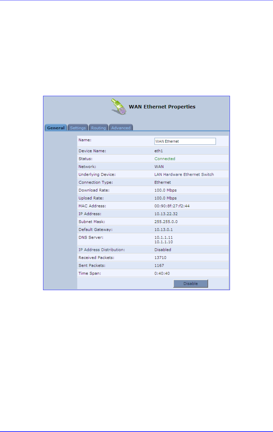
MP252 Multimedia Home Gateway 12. Network Connections
Version 3.4.0 171 June 2011
12.3.1 General Tab
The General tab displays mainly read-only properties of the connection.
The main actions that can be done in this tab screen includes the following:
Modifying the connection name – in the ‘Name’ field
Enabling and disabling the connection, by clicking the Enable or Disable button
respectively
Below shows an example of a General tab screen, displaying the ‘Name’ field and the
Disable button.
Figure 12-59: Editing Connection - General Tab (For Example, WAN Ethernet)
12.3.2 Settings Tab
The top part of the Settings tab screen displays general communication parameters. It is
recommended not to change the default values in this screen unless you are familiar with the
networking concepts they represent. Since your MP252 is configured to operate with the
default values, no parameter modification is necessary.
Figure 12-60: Editing Connection - Settings Tab (For Example, WAN Ethernet)
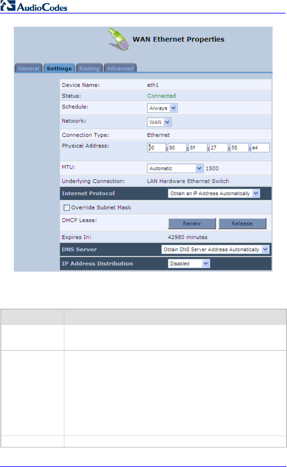
MP252 Multimedia Home Gateway 172 Document #: LTRT-23504
User's Manual
The Settings tab screen allows you to configure the following:
Table 12-2: Settings Tab - Parameter Descriptions
Parameter Description
Schedule You can select a Scheduler rule that defines time segments during which the
connection is active. To configure scheduler rules, see Section 4.5.1 on page
47.
Network Select whether the connection relates to a LAN, WAN, or DMZ connection.
Every network connection can be configured as one of these types. This
provides flexibility and increased functionality. For example, you may define that
a LAN Ethernet connection on MP252 operates as a WAN network. This means
that all hosts in this LAN will be referred to as WAN computers, both by
computers outside MP252 and by MP252 itself. WAN and firewall rules may be
applied, such as on any other WAN network.
Another example, is that a network connection can be defined as a DMZ
(D
emilitarized) network. Although the network is physically inside MP252, it will
function as an unsecured, independent network, for which MP252 merely acts
as a router.
Physical Address The physical address of the network card used for your network.
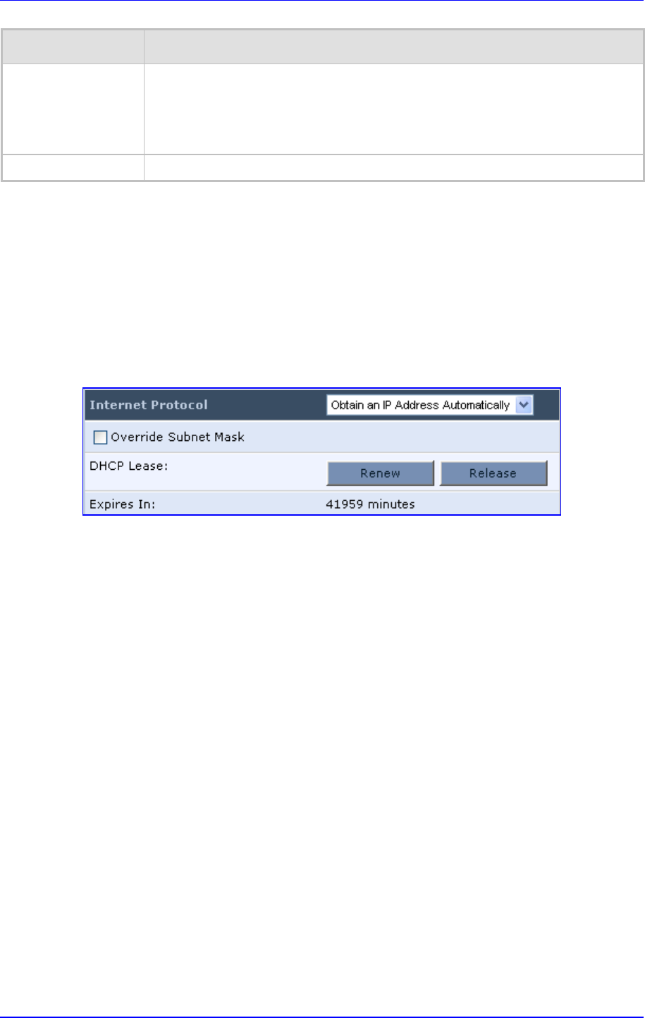
MP252 Multimedia Home Gateway 12. Network Connections
Version 3.4.0 173 June 2011
Parameter Description
MTU
Maximum Transmission Unit (MTU) species the largest packet size permitted for
Internet transmission. In the default setting, ‘Automatic’, the MP252 selects the
best MTU for your Internet connection. Select 'Automatic by DHCP' to have the
DHCP determine the MTU. In case you change to ‘Manual’, you can enter the
largest packet size, you should leave this value in the 1200 to 1500 range.
Internet Protocol For a description, see Section 12.3.2.1.
12.3.2.1 Internet Protocol Settings
The 'Internet Protocol' group defines the Internet Protocol options. Select one of the following
Internet Protocol options from the 'Internet Protocol' drop-down list:
No IP Address
Obtain an IP Address Automatically: Your WAN connection is configured by default
to act as a DHCP client. You should keep this configuration in case your service
provider supports DHCP, or if you are connecting using a dynamic IP address.
Figure 12-61: Automatically Obtaining an IP Address
The server that assigns the MP252 with an IP address also assigns a subnet mask. You
can override the dynamically assigned subnet mask by selecting the 'Override Subnet
Mask' check box and specifying your own mask instead.
You can click the Release button to release the current leased IP address. Once the
address has been released, the button text changes to 'Renew'. Use the Renew button
to renew the leased IP address.
For defining DNS and DHCP servers, see sections 12.3.2.1.1 and 12.3.2.1.2
respectively.
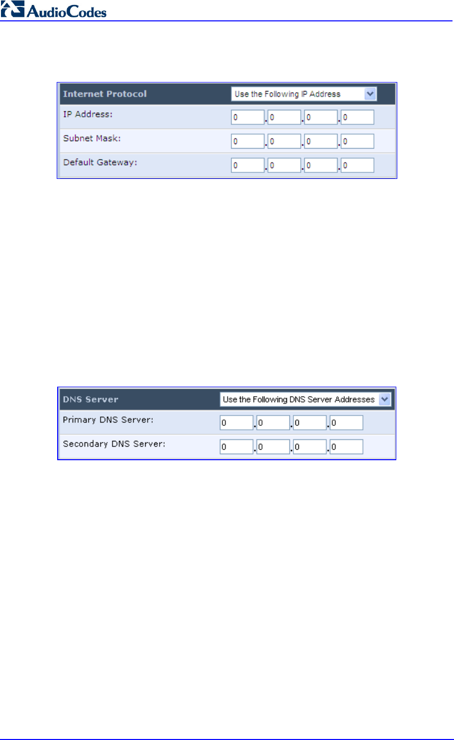
MP252 Multimedia Home Gateway 174 Document #: LTRT-23504
User's Manual
Use the Following IP Address: Your WAN connection can be configured using a
permanent (static) IP address. Your service provider should provide you with this IP
address, subnet mask and the default MP252 IP address.
For defining DNS and DHCP servers, see sections 12.3.2.1.1 and 12.3.2.1.2
respectively.
12.3.2.1.1 DNS Server
Domain Name System (DNS) is the method by which websites or domain names are
translated into IP addresses. You can configure the connection to automatically obtain a
DNS server address, or specify such an address manually, according to the information
provided by your ISP.
From the 'DNS Server' drop-down list, you can select one of the following methods:
Obtain DNS Server Address Automatically: the connection automatically obtains a
DNS server address.
Use the Following DNS Server Addresses: manually configure DNS server - specify
up to two different DNS server addresses - one primary, the other secondary:
Figure 12-62: Manually Defining DNS Server
No DNS Server: select this if there is no DNS server.
12.3.2.1.2 IP Address Distribution
The 'IP Address Distribution' section allows you to configure the device's Dynamic Host
Configuration Protocol (DHCP) server parameters. The DHCP automatically assigns IP
addresses to network PCs. If you enable this feature, make sure that you also configure your
network PCs as DHCP clients.
Select one of the following options from the 'IP Address Distribution' drop-down list:
Disabled: Select this option to statically assign IP addresses to your network
computers.
DHCP Server: Enables DHCP server:
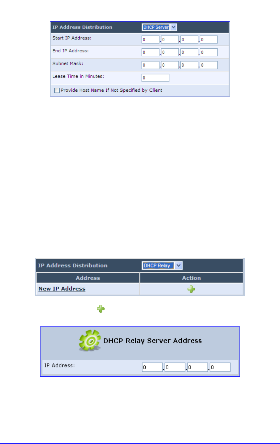
MP252 Multimedia Home Gateway 12. Network Connections
Version 3.4.0 175 June 2011
Figure 12-63: IP Address Distribution - DHCP Server
• Start IP Address: The first IP address that may be assigned to a LAN host. Since
the device's default IP address is 192.168.2.1, this address must be 192.168.2.2 or
greater.
• End IP Address: The last IP address in the range that can be used to
automatically assign IP addresses to LAN hosts.
• Subnet Mask: A mask used to determine to what subnet an IP address belongs.
• Lease Time In Minutes: Each device is assigned an IP address by the DHCP
server for this amount of time when it connects to the network. When the lease
expires, the server determines if the computer has disconnected from the network.
If it has, the server may reassign this IP address to a newly-connected computer.
This feature ensures that IP addresses that are not in use become available for
other computers on the network.
• Provide Host Name If Not Specified by Client: If the DHCP client does not have
a host name, the device automatically assigns one for him
DHCP Relay: The MP252 can act as a DHCP relay in case you would like to
dynamically assign IP addresses from a DHCP server other than MP252's DHCP server.
Note that when selecting this option, you must also change the device's WAN to work in
routing mode.
Figure 12-64: IP Address Distribution - DHCP Relay
1. Click the New icon; the 'DHCP Relay Server Address' screen appears:
Figure 12-65: DHCP Relay Server Address
2. Specify the IP address of the DHCP server, and then click OK to save the settings.
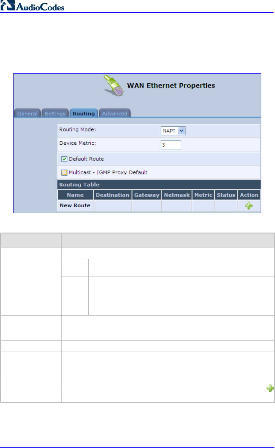
MP252 Multimedia Home Gateway 176 Document #: LTRT-23504
User's Manual
12.3.3 Routing Tab
You can choose to setup your MP252 to use static or dynamic routing. Dynamic routing
automatically adjusts how packets travel on the network, whereas static routing specifies a
fixed routing path to neighboring destinations.
Figure 12-66: Editing Connection - Routing Tab (For Example, WAN Ethernet)
Table 12-3: Routing Parameters
Parameter Description
Select one of the following Routing modes:
Route Use route mode if you want your MP252 to function as a router
between two networks.
Routing Mode
NAPT Network Address and Port Translation (NAPT) refers to network
address translation involving the mapping of port numbers, allowing
multiple machines to share a single IP address. Use NAPT if your LAN
encompasses multiple devices, a topology that necessitates port
translation in addition to address translation.
Device Metric
The device metric is a value used by the MP252 to determine whether one route
is superior to another, considering parameters such as bandwidth, delay, and
more.
Default Route Select this check box to define this device as a the default route.
Multicast - IGMP
Proxy Default
IGMP proxy enables the system to issue IGMP host messages on behalf of
hosts that the system discovered through standard IGMP interfaces. IGMP
proxy enables the routing of multicast packets according to the IGMP requests
of LAN devices asking to join multicast groups.
Routing Table Allows you to add or modify routes when this device is active. Click the New
icon to add a route (as shown in the figure below) or edit existing routes.
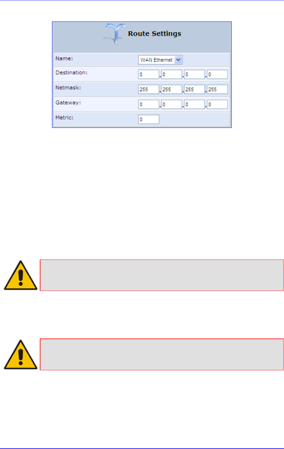
MP252 Multimedia Home Gateway 12. Network Connections
Version 3.4.0 177 June 2011
Figure 12-67: Route Settings Screen
Name: Select the network device.
Destination: destination host, subnet address, network address, or default route. The
destination for a default route is 0.0.0.0.
Netmask: Netmask used in conjunction with the destination to determine when a route
is used.
Gateway: Enter the MP252's IP address.
Metric: A measurement of the preference of a route. Typically, the lowest metric is the
most preferred route. If multiple routes exist to a given destination network, the route
with the lowest metric is used.:
12.3.4 Wireless Tab
For a description of the Wireless tab, see Section Error! Reference source not found. on
page Error! Bookmark not defined..
Note: This tab is applicable only to LAN Wireless connections.
12.3.5 Switch Tab
For a description of the Switch tab, see Section 12.2.2.2 on page 168.
Note: This tab is applicable only to LAN Hardware Ethernet Switch connections.
12.3.6 Bridging Tab
For a description of the Bridging tab, see Section 12.5.1 on page 190.
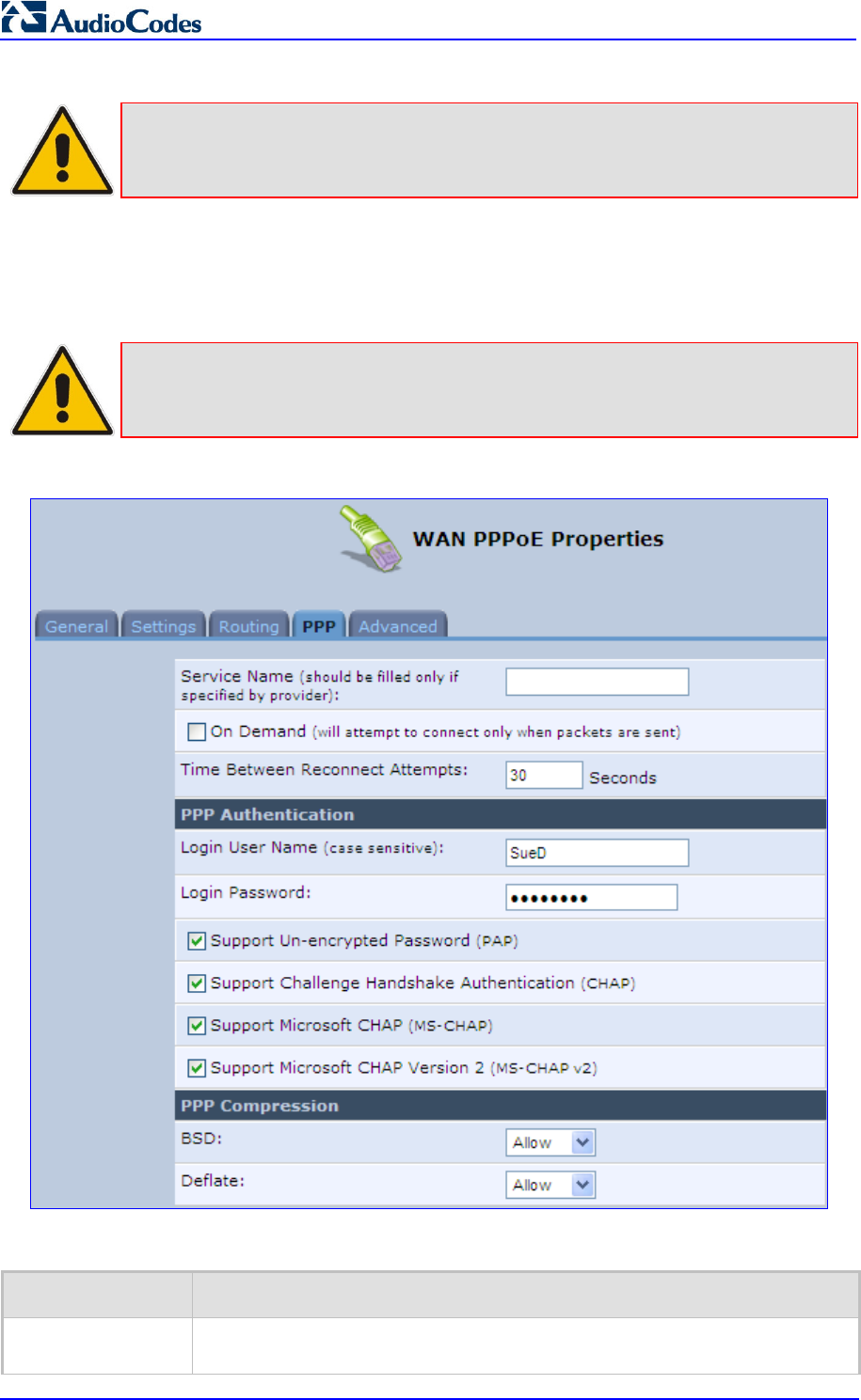
MP252 Multimedia Home Gateway 178 Document #: LTRT-23504
User's Manual
Note: This tab is applicable only to LAN-WAN Bridging connections.
12.3.7 PPP Tab
The PPT tab displays the PPPoE settings.
Note: This tab is applicable only to PPP connections.
Figure 12-68: Editing Connection - PPP Tab
Table 12-4: PPP Tab Parameter Descriptions
Parameter Description
On Demand
Use PPP on demand to initiate the PPP session only when packets are actually
sent over the Internet.

MP252 Multimedia Home Gateway 12. Network Connections
Version 3.4.0 179 June 2011
Parameter Description
Idle Time Before
Hanging Up
Specify the amount of idle time (during which no data is sent or received) that
should elapse before the gateway disconnects the PPP connection.
Note: This parameter appears only if On Demand is selected.
Time Between
Reconnect
Attempts
Specify the duration between PPP reconnected attempts, as provided by your
ISP.
PPP Authentication
PPP supports four authentication protocols: Password Authentication Protocol
(PAP), Challenge Handshake Authentication Protocol (CHAP), Microsoft CHAP
version 1, and Microsoft CHAP version 2.
This section allows you to select the authentication protocols your MP252 may
use when negotiating with a PPTP server. Select all the protocols if no
information is available about the server's authentication protocols. Note that
encryption is p
erformed only if 'Microsoft CHAP', 'Microsoft CHAP version 2', or
both are selected.
Login User Name: login username according to ISP
Login Password: login password according to ISP
Support Un-encrypted Password (PAP): PAP is a simple, plaintext
authe
ntication scheme. The username and password are requested by your
networking peer in plain text. PAP, however, is not a secure authentication
protocol. Man-in-the-
middle attacks can easily determine the remote access
client's password. PAP offers no protection against replay attacks, remote
client impersonation, or remote server impersonation.
Support Challenge Handshake Authentication (CHAP): CHAP is a
challenge-response authentication protocol that uses MD5 to hash the
response to a challenge. CHAP protects against replay attacks by using an
arbitrary challenge string per authentication attempt.
Support Microsoft CHAP: Select this check box if you are communicating
with a peer that uses Microsoft CHAP authentication protocol.
Support Microsoft CHAP Version 2: Select this check box if you are
communicating with a peer that uses Microsoft CHAP Version 2
authentication protocol.
PPP Compression The PPP Compression Control Protocol (CCP) is responsible for configuring,
enabling, and disabling data compression algorithms on both ends of the
point-to-point link. It is also used to signal a failure of the compression/
decompression mechanism in a reliable manner. For each compression
algorithm, select one of the following from the drop down menu.
Reject: Reject PPP connections with peers that use the compression
algorithm.
Allow: Allow PPP connections with peers that use the compression
algorithm.
Require: Ensure a connection with a peer is using the compression
algorithm.
12.3.8 PPTP tab
The PPTP tab displays the PPTP settings.
Note: This tab is applicable only to PPTP connections.
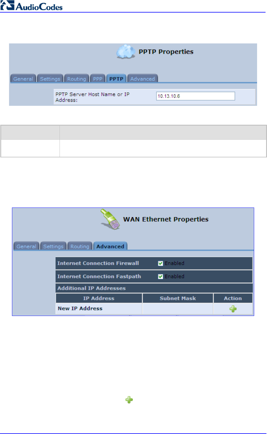
MP252 Multimedia Home Gateway 180 Document #: LTRT-23504
User's Manual
Figure 12-69: Editing Connection - PPTP Tab
Table 12-5: PPTP Tab Parameter Descriptions
Parameter Description
PPTP Server Host
Name or IP Address
PPTP server host name or IP address provided by your ISP.
12.3.9 Advanced Tab
The Advanced tab provides various advanced configurations.
Figure 12-70: Editing Connection - Advanced Tab (For Example, WAN Ethernet)
Internet Connection Firewall: Your MP252's firewall helps protect your computer by
preventing unauthorized users from gaining access to it through a network such as the
Internet. The firewall can be activated per network connection. To enable the firewall on
this network connection, select the 'Enabled' check box. You can click the Internet
Connection Firewall link to access the ‘Security’ screen (see Section 14.1 on page
226).
Internet Connection Fastpath: Select this check box to utilize the Fastpath algorithm
for enhancing packet flow, resulting in faster communication between the LAN and the
WAN.
Additional IP Addresses: You can also add alias names (additional IP addresses) to
the MP252, by clicking the New icon. This enables you to access the MP252 using
these aliases in addition to the default IP addresses.
Figure 12-71: Additional IP Address Settings Screen
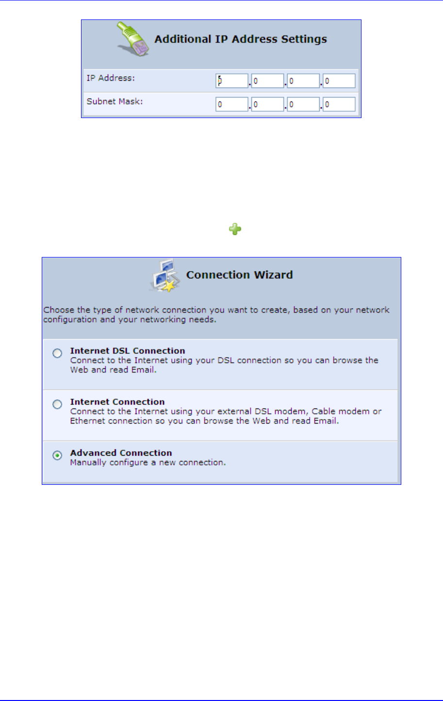
MP252 Multimedia Home Gateway 12. Network Connections
Version 3.4.0 181 June 2011
12.4 VLAN Settings
To create a new VLAN interface:
1. From the menu bar, click the Network Connections menu, and then in the screen
'Network Connections' click the New icon; the 'Connection Wizard' screen appears.
Figure 12-72: Connection Wizard Screen
2. Select the 'Advanced Connection' option, and then click Next; the 'Advanced
Connection' screen appears.
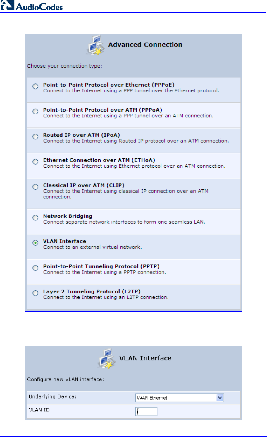
MP252 Multimedia Home Gateway 182 Document #: LTRT-23504
User's Manual
Figure 12-73: Advanced Connection
3. Select the 'VLAN Interface' option, and then click Next; the 'VLAN Interface' screen
appears.
Figure 12-74: VLAN Interface
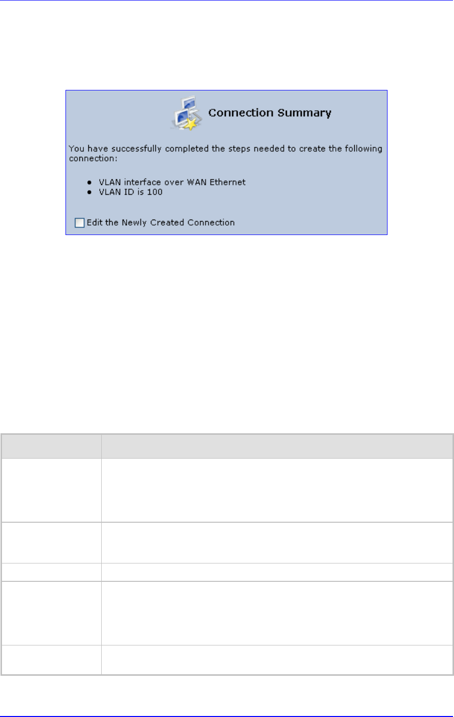
MP252 Multimedia Home Gateway 12. Network Connections
Version 3.4.0 183 June 2011
4. From the 'Underlying Device' drop-down list, select the underlying device (device's
Ethernet connections) for this interface.
5. In the 'VLAN ID' field, enter a value to serve as the VLAN ID, and then click Next; the
'Connection Summary' screen appears.
Figure 12-75: Connection Summary
6. Check the 'Edit the Newly Created Connection' check box to be routed to the new
connection's configuration screen after clicking Finish.
7. Click Finish to save the settings; the new VLAN interface is added to the network
connections list; it’s configurable like any other connection.
12.4.1 Settings Tab
The Settings tab of the 'VLAN Properties' displays general communication parameters. It’s
recommended to leave the values in this screen at their defaults unless you’re familiar with
the networking concepts they represent. Since your Telephone Adapter is configured to
operate with the default values, no parameter modification is necessary. You can configure
the following general connection settings:
Table 12-6: VLAN Interface - General Communication Parameters
Parameter Description
Schedule By default, the connection is always active. However, you can configure
scheduler rules in order to define time segments during which the connection
may be active. Once a scheduler rule(s) is defined (via Advanced>Scheduler
Rules), this field changes to a drop-down list, allowing you to choose between
the available rules. To configure scheduler rules, see Section 10.11.
Network Select whether the parameters you are configuring relate to a WAN, LAN or
DMZ connection, by selecting the connection type from the drop-down list. For
detailed information, see Section 4.2.
Physical Address The physical address of the network card used for your network.
MTU MTU is the Maximum Transmission Unit. It specifies the largest packet size
permitted for Internet transmission. In the default setting, Automatic, the
Telephone Adapter selects the best MTU for your Internet connection. In case
you change to manual, you can enter the largest packet size, you should leave
this value in the 1200 to 1500 range.
Underlying
Connection
The Ethernet device that the connection is implemented over.
Select one of the following Internet Protocol options from the 'Internet Protocol' drop down
menu:

MP252 Multimedia Home Gateway 184 Document #: LTRT-23504
User's Manual
No IP Address
Obtain an IP Address Automatically
Use the Following IP Address
Note that according to the selection you make in the 'Internet Protocol' drop down menu, the
screen refreshes and displays relevant configuration settings.
No IP Address: Select 'No IP Address' if you require that your Telephone Adapter has
no IP address. This can be useful if you are working in an environment where you are
not connected to other networks, such as the Internet.
Obtain an IP Address Automatically: Your WAN connection is configured by default
to act as a DHCP client. You should keep this configuration in case your service
provider supports DHCP, or if you are connecting using a dynamic IP address. The
server that assigns the Telephone Adapter with an IP address also assigns a subnet
mask. You can override the dynamically assigned subnet mask by selecting the
'Override Subnet Mask' and specifying your own mask instead. You can click the
Release button to release the current leased IP address. Once the address has been
released, the button text changes to 'Renew'. Use the Renew button to renew the
leased IP address.
Use the Following IP Address: Your WAN connection can be configured using a
permanent (static) IP address. Your service provider should provide you with this IP
address, subnet mask and the default Telephone Adapter IP address.
12.4.1.1 IP Address Distribution
The 'IP Address Distribution' section allows you to configure the device's Dynamic Host
Configuration Protocol (DHCP) server parameters. The DHCP automatically assigns IP
addresses to network PCs. If you enable this feature, make sure that you also configure your
network PCs as DHCP clients. For a comprehensive description of this feature, see Section
10.28.
Select one of the following options from the 'IP Address Distribution' drop-down list:
Table 12-7: IP Address Distribution Parameters
Parameter Description
DHCP Server
Start IP Address The first IP address that may be assigned to a LAN host. Since
the device's default IP address is 192.168.2.1, this address must be 192.168.2.2
or greater.
End IP Address The last IP address in the range that can be used to automatically assign IP
addresses to LAN hosts.
Subnet Mask
A mask used to determine to what subnet an IP address belongs. An example of
a subnet mask value is 255.255.0.0.
Lease Time In
Minutes
Each device is assigned an IP address by the DHCP server for a this amount of
time, when it connects to the network. When the lease expires the server
determines if the computer has disconnected from the network. If it has, the
server may reassign this IP address to a newly-connected computer. This
feature ensures that IP addresses that are not in use become available for other
computers on the network.
Provide Host Name If
Not Specified by
Client
If the DHCP client does not have a host name, the d
evice automatically assigns
one for him.
Figure 12-76: IP Address Distribution - DHCP Server
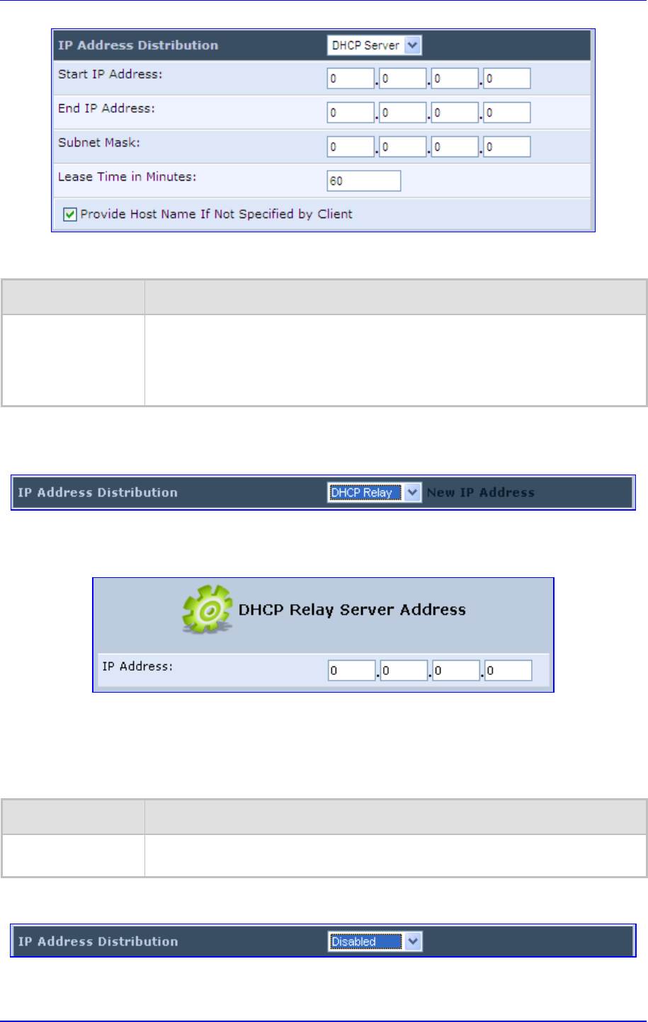
MP252 Multimedia Home Gateway 12. Network Connections
Version 3.4.0 185 June 2011
Table 12-8: DHCP Relay
Parameter Description
DHCP Relay Your device can act as a DHCP relay in case you would like to dynamically
assign IP addresses from a DHCP server other than your Telephone Adapter's
DHCP server. Note that when selecting this option you must also change the
device's WAN to work in routing mode. For detailed information, see Section
10.28.2.
1. After selecting 'DHCP Relay' from the drop down list, a New IP Address link appears:
Figure 12-77: IP Address Distribution - DHCP Relay
2. Click the New IP Address link; the 'DHCP Relay Server Address' screen appears:
Figure 12-78: DHCP Relay Server Address
3. Specify the IP address of the DHCP server.
4. Click OK to save the settings.
Table 12-9: Assigning Static IP Addresses to Network Computers
Parameter Description
Disabled Select 'Disabled' from the drop-
down list to statically assign IP addresses to your
network computers.
Figure 12-79: IP Address Distribution - Disable DHCP
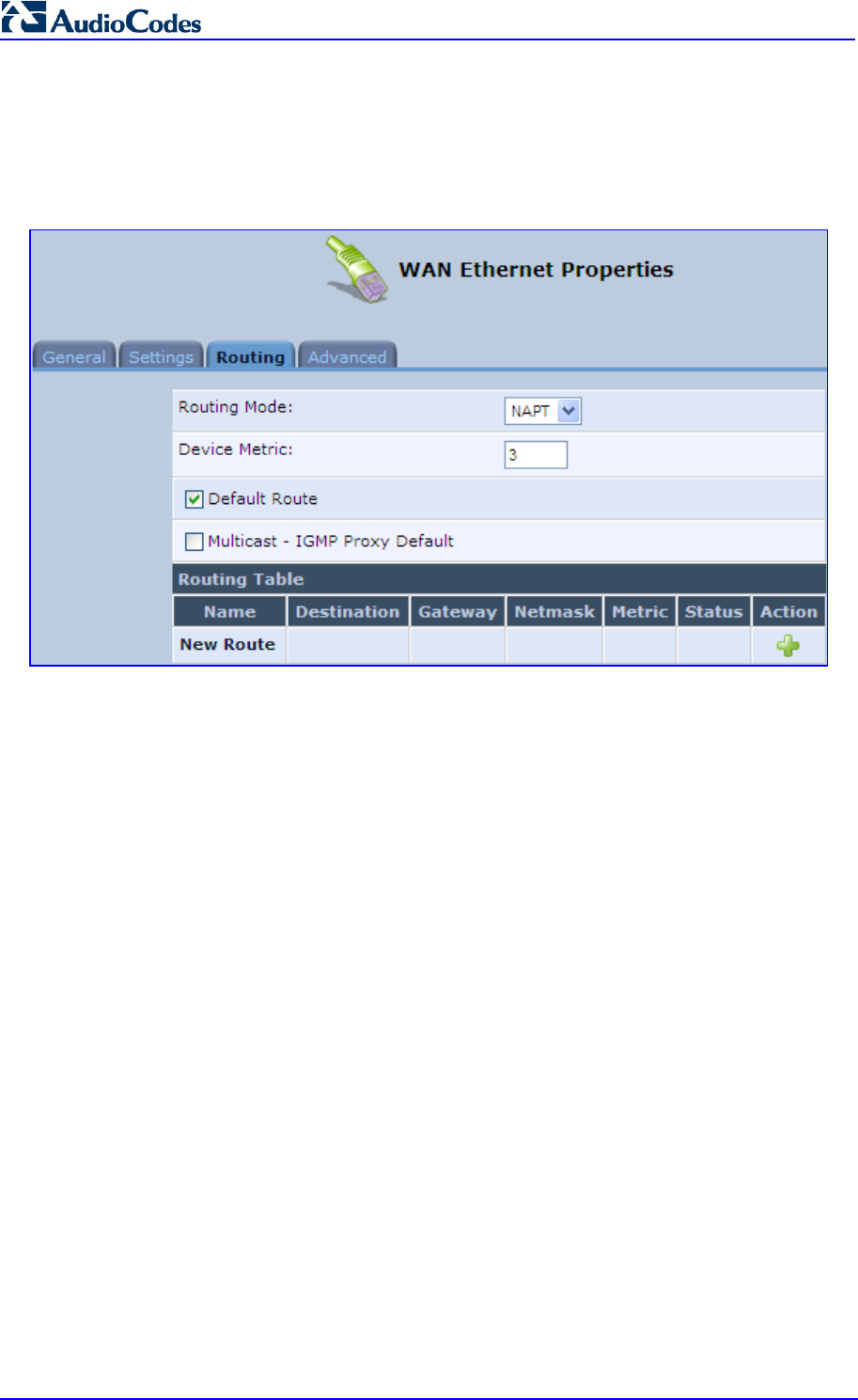
MP252 Multimedia Home Gateway 186 Document #: LTRT-23504
User's Manual
12.4.2 Routing Tab
You can choose to setup your Telephone Adapter to use static or dynamic routing. Dynamic
routing automatically adjusts how packets travel on the network, whereas static routing
specifies a fixed routing path to neighboring destinations.
Figure 12-80: Advanced Routing Properties

MP252 Multimedia Home Gateway 12. Network Connections
Version 3.4.0 187 June 2011
Table 12-10: Routing Parameters
Parameter Description
Routing Select 'Advanced' or 'Basic' routing.
Routing Mode Select one of the following Routing modes:
Route: Use route mode if you want your device to function as a router
between two networks.
NAT:
Network Address Translation (NAT) translates IP addresses to a valid,
public address on the Internet. This adds security since internal LAN
addresses are not transmitted over the Internet. In addition, NAT allows
many addresses to exist behind a single valid address. Use the NAT routing
mode if your LAN consists of a single device, otherwise collisions may occur
if more than one device attempts to communicate using the same port.
NAPT: Network Address and Port Translation (NAPT) refers to network
address translation involving the mapping of port numbers, allowing multiple
machines to share a single IP address. Use NA
PT if your LAN encompasses
multiple devices, a topology that necessitates port translation in addition to
address translation.
Device Metric The device metric is a value used by
the device to determine whether one route
is superior to another, considering parameters such as bandwidth, delay, and
more.
Default Route Select this check box to define this device as a the default route.
Multicast IGMP Proxy Internal IGMP proxy enables the system to issue IGMP host
messages on behalf of hosts that the system discovered through standard IGMP
interfaces. IGMP proxy enables the routing of multicast packets according to the
IGMP requests of LAN devices asking to join multicast groups. Select the
'Multicast IGMP Proxy Internal' check-box to enable this feature.
Routing Table Allows you to add or modify routes when this device is active. Use the New
Route button to add a route or edit existing routes.
12.4.3 Advanced Tab
Your Telephone Adapter’s firewall helps protect your computer by preventing unauthorized
users from gaining access to it through a network such as the Internet. The firewall can be
activated per network connection. To enable the firewall on this network connection, select
the 'Enabled' check box. For detailed information on your device's security features, see
Section 5.
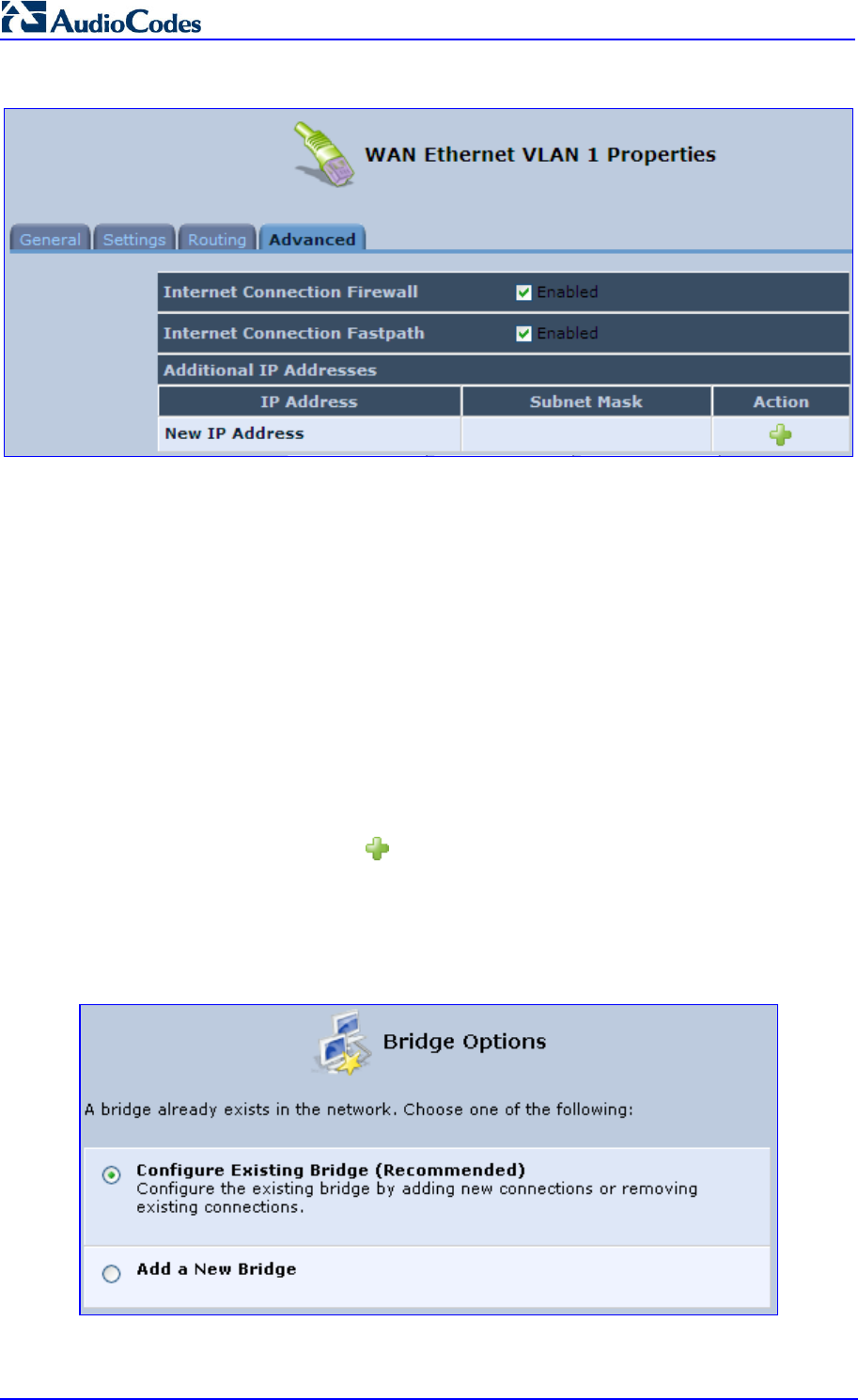
MP252 Multimedia Home Gateway 188 Document #: LTRT-23504
User's Manual
Figure 12-81: Internet Connection Firewall
You can add alias names (additional IP addresses) to the MP252 by clicking the 'New IP
Address' link. This enables you to access the device using these aliases in addition to the IP
address (e.g., 192.168.2.1) and http://mp252.home.
12.5 LAN-WAN Bridge Settings
A WAN-LAN bridge is a bridge over WAN and LAN devices. In such a setup, computers on
the MP252 LAN side can get IP addresses that are known on the WAN side.
To configure an existing bridge or create a new one:
1. From the menu bar, click the Network Connections menu, and in the screen 'Network
Connections' click the New icon; the 'Connection Wizard' screen appears.
2. Select the 'Advanced Connection' option, and then click Next; the 'Advanced
Connection' screen appears.
3. Select the 'Network Bridging' option, and then click Next; the screen 'Bridge Options'
opens.
Figure 12-82: Bridge Options
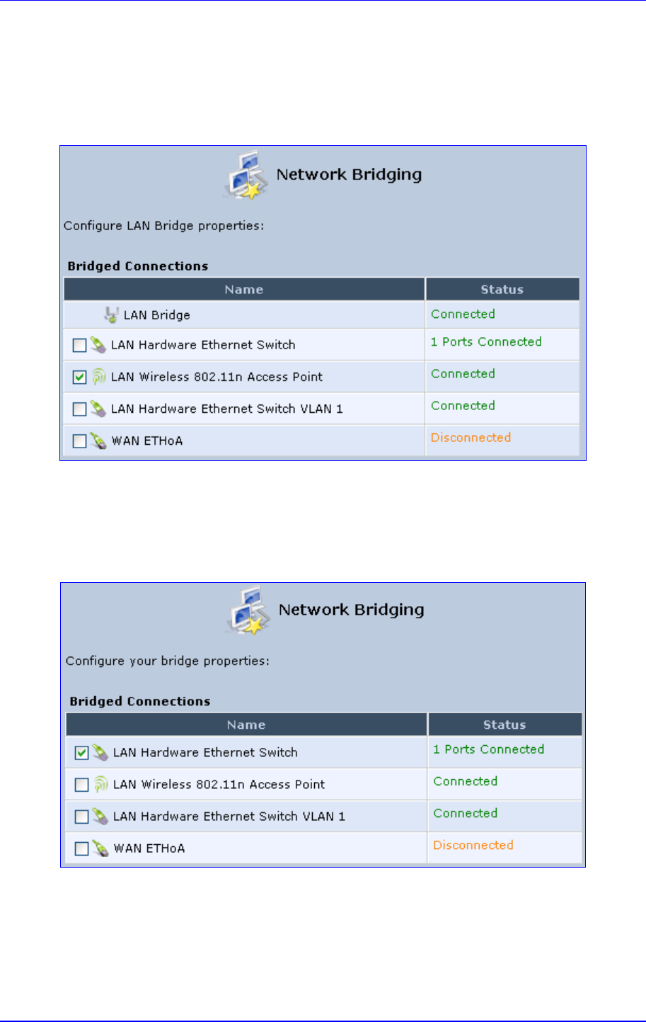
MP252 Multimedia Home Gateway 12. Network Connections
Version 3.4.0 189 June 2011
4. Select whether to configure an existing bridge (this option only appears if a bridge exists)
or to add a new one:
• Configure Existing Bridge: Select this option and then click Next; the screen
'Network Bridging' opens, allowing you to add new connections or remove existing
ones, by selecting or clearing their respective check boxes.
Figure 12-83: Network Bridging Screen
For example, checking the WAN check box creates a LAN-WAN bridge.
• Add a New Bridge: Select this option and then click Next; a different 'Network
Bridging' screen appears, allowing you to add a bridge over the unbridged
connections, by selecting their respective check boxes.
Figure 12-84: Adding New Network Bridging
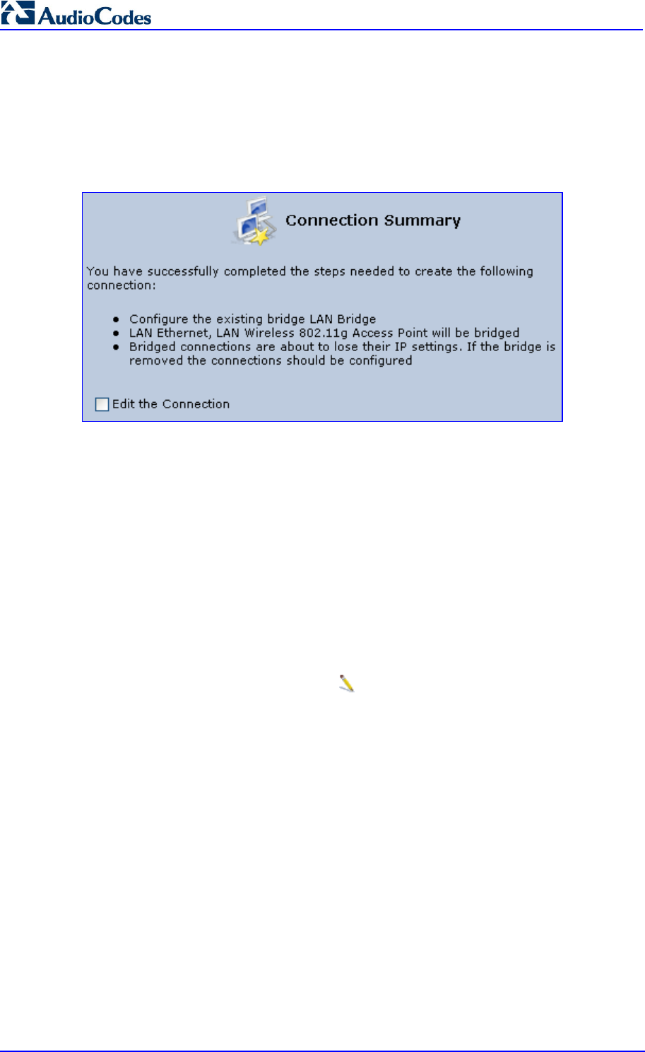
MP252 Multimedia Home Gateway 190 Document #: LTRT-23504
User's Manual
Important notes:
• The same connections cannot be shared by two bridges.
• A bridge cannot be bridged.
• Bridged connections lose their IP settings.
5. Click Next; the screen 'Connection Summary' opens, corresponding to your changes.
Figure 12-85: Connection Summary - Configure Existing Bridge
6. Select the check box 'Edit the Connection' to be routed to the new connection's
configuration screen after clicking Finish.
7. Click Finish to save the settings; the new bridge is added to the network connections
list; it's configurable like any other bridge.
12.5.1 Editing LAN-WAN Bridging
You can edit existing LAN-WAN bridges that are listed in the Connections list. This is done in
the Bridging tab, which allows you to specify the LAN and WAN devices that you would like
to join under the network bridge.
To edit LAN-WAN bridging:
1. From the menu bar, click the Network Connections menu, and then in the screen
'Network Connections' click the Edit icon corresponding the bridged network; the
'Connection Wizard' screen appears.
2. Click the Bridge tab; the LAN Bridge Properties screen appears.
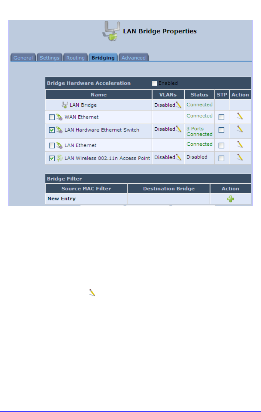
MP252 Multimedia Home Gateway 12. Network Connections
Version 3.4.0 191 June 2011
Figure 12-86: Bridging Tab
3. Select the check boxes corresponding to the connection names that you want to bridge,
or clear the check boxes of connections that you do not want to bridge.
4. Select the ‘Bridge Hardware Acceleration’ check box to utilizes the Fastpath algorithm,
which enhances packet flow, resulting in faster communication between the LAN and
the WAN (excluding the wireless connection).
5. Select the 'STP' check box to enable the Spanning Tree Protocol (STP) on the device.
You should use this to ensure that there are no loops in your network configuration, and
apply these settings if your network consists of multiple switches, or other bridges apart
from those created by the MP252
6. To configure VLANs for each network connection in the bridge:
a. Click the Edit icon in the 'VLANs' column corresponding to a network that you
want to assign specific Virtual LANs; the ‘VLAN Settings’ screen appears.
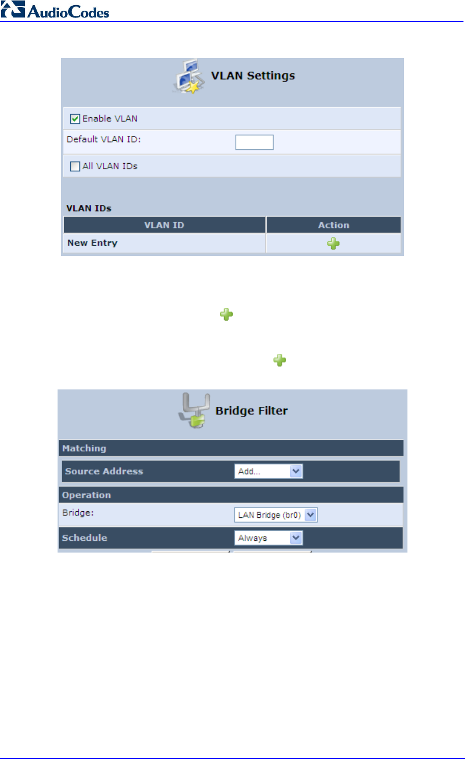
MP252 Multimedia Home Gateway 192 Document #: LTRT-23504
User's Manual
Figure 12-87: VLAN Settings Screen
b. Select the ‘Enable VLAN’ check box to enable VLANs on this connection; the
screen refreshes and additional parameters appear.
c. In the ‘Default VLAN ID’ field, enter a VLAN ID for this connection or add additional
VLANs by clicking the New icon, and then enter another VLAN ID.
7. To create a traffic filtering rule on the bridge to enable direct packet flow between the
WAN and the LAN (i.e., Bridge Filtering):
a. In the ‘Bridge Filter’ table, click the New icon; the ‘Bridge Filter’ screen appears.
Figure 12-88: Bridge Filter Screen
b. From the ‘Source Address’ drop-down list, select a Network Object (defined in
Section 4.5.2 on page 50) or create a new one by clicking ‘User Defined’. You can
define a traffic filtering rule that enables direct packet flow between the WAN and
the LAN host that will be placed under the WAN-LAN bridge. This filtering rule can
be based on either a LAN host's MAC address or one of its DHCP options.
c. From the 'Operation' drop-down list, select the bridge.
d. Click OK.

Version 3.4.0 193 July 2011
MP252 Multimedia Home Gateway 13. Remote MP252 Management
13 Remote MP252 Management
This chapter provides an overview of the MP252 remote configuration and management
support. In addition, this chapter describes how to enable and secure remote management,
as well configure MP252 through SNMP and TR069.
13.1 Overview
MP252 is designed to be mass-deployed. One of the keys to guarantee end-user satisfaction
and true toll-quality service in mass field deployment is comprehensive remote configuration
and management capabilities:
Automatic and remote configuration updates
Automatic and remote firmware updates
Remote diagnosis of problems reported by the user
Remote collection of statistical information regarding the quality of the service
Remote notifications of problems in the service
13.1.1 Remote Configuration
By default, MP252 is provided with factory default settings, which are common to all MP252
devices (except for the MAC address). The factory settings allow the user to connect to
MP252's Web interface through the LAN.
By default, the WAN interface is configured for DHCP (i.e., automatically obtains its IP
address from a DHCP server). The default configuration should not include any VoIP service
provider settings (such as a SIP proxy).
In some cases, AudioCodes can ship MP252 devices that are pre-configured with some
customer-specific parameters. This set of parameters is usually defined as the new "factory
settings" for the specific customer.
MP252's factory default settings and the current configuration running on MP252 are stored
on MP252's non-volatile flash memory. The current configuration can be remotely updated
using several configuration interfaces:
HTTP-based Web server
SNMP
TR-069
Configuration file upload/download
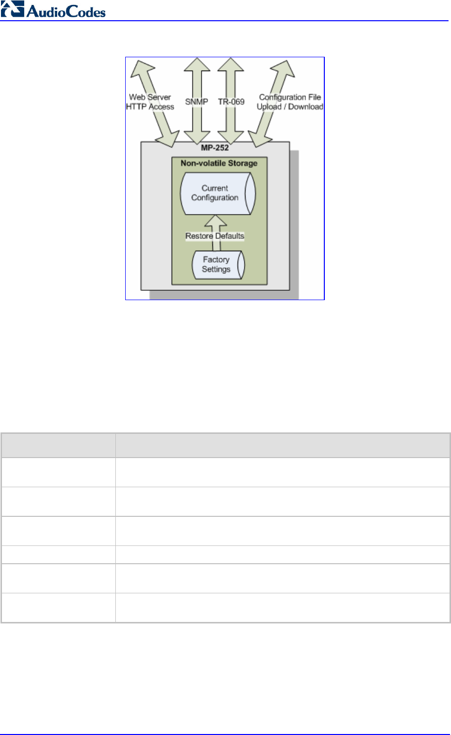
MP252 Multimedia Home Gateway 194 Document #: LTRT-23504
User's Manual
Figure 13-1: Remote Management Interfaces
All configuration interfaces access the same internal configuration repository. The
configuration file represents the complete set of MP252 configuration parameters. Specific
configuration interfaces (e.g. SNMP and TR-069) might support access only to a sub-set of
these configuration parameters.
At any time, the factory settings can be restored using the Web interface or by pressing the
Reset pin-hole button while MP252 is being powered up.
The table below lists the main MP252 configuration parameter groups:
Table 13-1: Main Configuration Parameter Groups
Group Description
VoIP Parameters relating to the VoIP functionality (e.g. analog interface, SIP
signaling, voice and fax, media streaming)
WAN Interface The main WAN Internet connection (this group is also referred to as the
"Quick Setup").
Network Connections Configuration of all network connections (LAN and WAN), including
advanced connections such as VLANs.
Security Parameters relating to the internal firewall.
QoS Configuration of Quality of Service parameters such as priorities and traffic
shaping.
System / Advanced Configuration of system parameters such as Remote Update and Remote
Access and advanced parameters such as Dynamic DNS, UPnP.
A typical set of parameters that a service provider may want to configure include the
following:
Remote access and/or automatic firmware and configuration update parameters
VoIP configuration: SIP proxy, line settings (User IP, Password)
QoS parameters (e.g. traffic shaping)
13.1.2 Remote Management
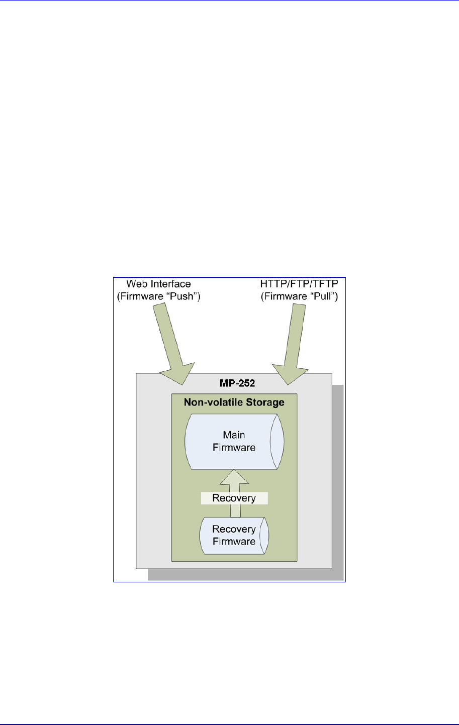
MP252 Multimedia Home Gateway 13. Remote MP252 Management
Version 3.4.0 195 June 2011
Remote management includes the following:
Firmware upgrade
Status and performance monitoring
Alarms, notifications, and logs
13.1.2.1 Firmware Upgrade
Service providers require the ability to update MP252's firmware in the field (e.g. in case of
maintenance releases or releases that support new required features). The process is
required to be automatic, allowing mass update, which is robust and fail-safe.
MP252's firmware is stored on the non-volatile flash memory. MP252's flash memory is
capable of storing a recovery firmware that ensures a fail-safe operation (even if the user
unplugs the power during the firmware burning process).
MP252's firmware can be upgraded using one of the following mechanisms:
The new firmware can be "pushed" (uploaded) to MP252, using the MP252 Web
interface
The new firmware can be "pulled" (downloaded) by MP252 from a remote HTTP, FTP,
or TFTP server
Figure 13-2: Firmware Upgrade Mechanism
MP252 Multimedia Home Gateway 196 Document #: LTRT-23504
User's Manual
The remote firmware download process can be triggered by one of the following:
MP252 checks for a new firmware upon MP252 restart
MP252 periodically checks for a new firmware
Manual trigger using CLI, TR-069, SNMP or Web
Note: Unless forced, MP252 downloads and upgrades to the new firmware only if its
version number is higher than the firmware version currently running on MP252.
The version number is not taken from the image file name, but from the header
of the image file.
13.1.2.2 Status and Performance Monitoring
The ability to remotely monitor the status of MP252 is critical to the service provider, who
wants to support users without having to send a technician on site (avoiding the "truck roll").
The service provider may want to know the current status of MP252 (e.g. is it registered to
the SIP proxy, is the phone off-hook) or some statistical information (e.g. average packet loss
during a call).
MP252 maintains a set of status and performance information internally. This information (or
parts of it) can be retrieved via the different management interfaces (e.g. Web, or TR-069).
The table below describes the status and performance monitoring (statistical) information
available in MP252.
Table 13-2: Status and Performance Monitoring Parameters
Group Description
VoIP
Current status information per line:
Phone state
Registration status
Source, codec and type of current call
Packet loss, jitter and delay of current call
Network Connections
Current status information per interface:
Connection status
Allocated IP address
Received and transmitted packets
System
Software version information
Hardware version information
System Up time

MP252 Multimedia Home Gateway 13. Remote MP252 Management
Version 3.4.0 197 June 2011
13.1.2.3 Alarms, Notifications and Logging
Instead of periodically polling MP252 to obtain its current status, the service provider may
want MP252 to notify abnormal events or to send regular reports to a logging server. Both
options are supported by MP252. The table below lists the relevant interfaces for alarms and
notifications.
Table 13-3: Notifications and Logged Events
Group Notifications and Logged Events
VoIP
Notifications: Registration error or timeout
Logged Events:
End of call (Call Detail Record logging)
SIP messages logging (optional - for debugging)
Network Connections
Notifications: Connection up / down
Security
Logged Events: Security log (configurable)
System
Notifications:
System restart
Firmware / configuration update
Logged Events: Debug-level logging (optional)
Note that the terms Alarm and Notification represent the same thing. The difference between
alarm/notification and logging is that an alarm is normally used to represent an abnormal
event (e.g. registration error), while logged events can represent either regular events (e.g.
end of call) or abnormal events.
The table below lists the event severity levels defined in MP252. Typically, events with
severity of Error or Emergency are notified in addition to being logged.
Table 13-4: Severity of Logged Events
Severity Description
Debug Debug-level messages.
Notice Normal but significant condition. Notices requiring attention at a later time.
Non-error conditions that might require special handling.
Error Recoverable / temporary error condition.
Emergency
System is unusable. The most severe messages that prevent continuation of
operation, such as immediate system shutdown.
13.2 Enabling Remote Management
You can access and manage MP252 not only from within the home network, but also from
the Internet. This allows you to view or change settings while travelling. It also enables you to
allow your ISP to change settings or help you troubleshoot functionality or communication
issues from a remote location.
Remote access to MP252 is blocked by default to ensure the security of your home network.
However, remote access is supported by the following services, and you may use the
'Remote Access Configuration' screen to selectively enable these services if they are
needed.

MP252 Multimedia Home Gateway 198 Document #: LTRT-23504
User's Manual
Notes:
• Telnet and Web-Management can be used to modify the settings of the
firewall or to disable it. You can also change local IP addresses and other
settings, making it difficult or impossible to access MP252 from the home
network. Therefore, remote access to Telnet or HTTP services should be
blocked and should only be permitted when absolutely necessary.
• Encrypted remote administration is done using a secure SSL connection
that requires an SSL certificate. When accessing MP252 for the first time
using encrypted remote administration, you are prompted by your browser
with a warning regarding certificate authentication. This is because
MP252's SSL certificate is self generated. When encountering this
message under these circumstances, ignore it and continue. It should be
noted that even though this message appears, the self-generated
certificate is safe, and provides you with a secure SSL connection. You
can also assign a user-defined certificate to MP252.
To enable remote access to MP252 services:
1. In the 'Advanced' screen, click the Remote Administration icon; the 'Remote
Administration' screen appears.
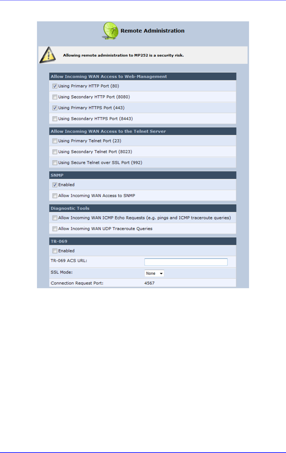
MP252 Multimedia Home Gateway 13. Remote MP252 Management
Version 3.4.0 199 June 2011
Figure 13-3: Remote Administration Screen
2. Select the services that you would like to make available to computers on the Internet.
• Allow Incoming WAN Access to Web-Management: Allows access (from a Web
browser) to the Web management interface and to all system settings and
parameters. Both secure (HTTPS) and non-secure (HTTP) access is available.
• Allow Incoming WAN Access to the Telnet Server: Allows access to the
command-line session and to all system settings and parameters (using a
text-based terminal).
• SNMP: Allows Simple Network Management Protocol (SNMP) requests to
remotely configure and monitor MP252.
• Diagnostic Tools: Allows remote access for ping and traceroute (over UDP)
troubleshooting.
• TR-069: TR-069 is a WAN management protocol for communication between
Customer Premise Equipment (CPE) and an Auto-Configuration Server (ACS). It
defines a mechanism that encompasses secure auto-configuration of a CPE, and
also incorporates other CPE management functions into a common framework.
3. Click OK to save your changes.
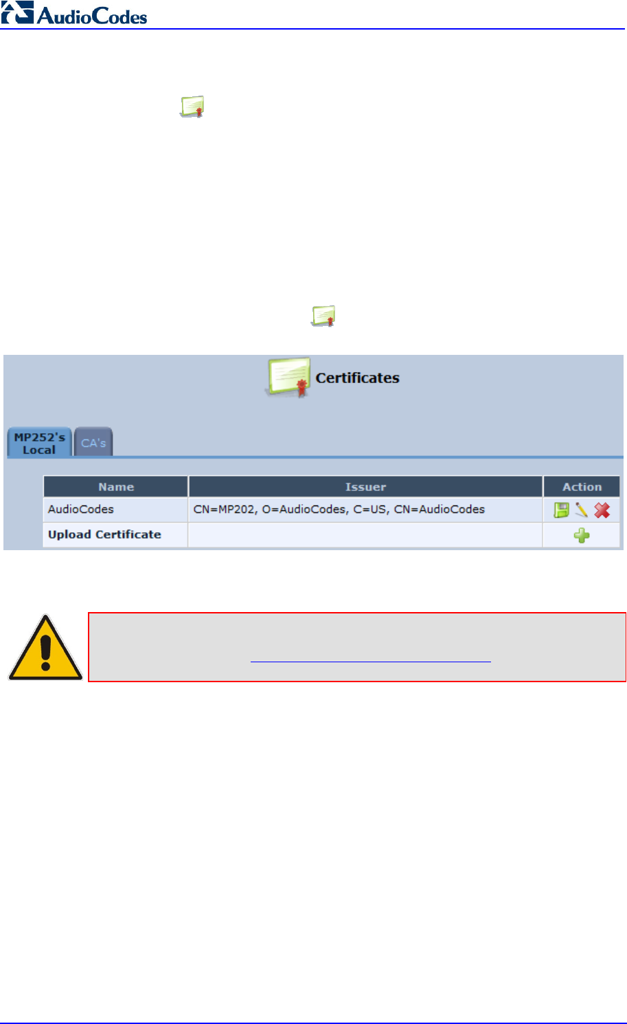
MP252 Multimedia Home Gateway 200 Document #: LTRT-23504
User's Manual
13.3 Securing Remote Management with Certificates
The Certificates icon allows you to configure certificates. When a service provider
implements remote provisioning in which a unique configuration file (per MP252) is placed on
a server located on the WAN, the service provider can ensure that only its deployed MP252
units are able to connect to the HTTP server via HTTPS. This is performed by using a
certification validation process (client-server).
There are two types of certificates:
Self-signed certificates
Certificate Authority (CA) signed certificates
The procedure below describes how to operate with self-signed certificates.
To operate with self-signed certificates:
1. In the 'Advanced' screen, click the icon; the 'Certificates' screen appears.
Figure 13-4: New Certificates Screen
2. Create a self-signed certificate:
Note: You can also create a self-signed certificate using the OpenSSL utility,
downloaded from http://sial.org/howto/openssl/self-signed.
a. Select the MP252’s Local tab.
b. Click the Create Self Signed Certificate button; the 'Create Self Signed X509
Certificate' screen appears.