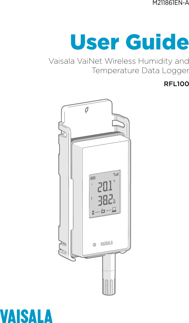
Vaisalaj RFL100A Wireless data logger User Manual User Guide M211861EN A
Vaisala Oyj Wireless data logger User Guide M211861EN A
UserManual.wiki
>
Vaisalaj
>
RFL100A User Manual
User Manual
Navigation menu
Upload a User Manual
Namespaces
Wiki Guide
HTML
PDF
Info
Views
User Manual
Discussion / Help
Navigation
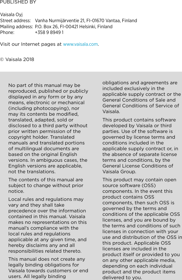
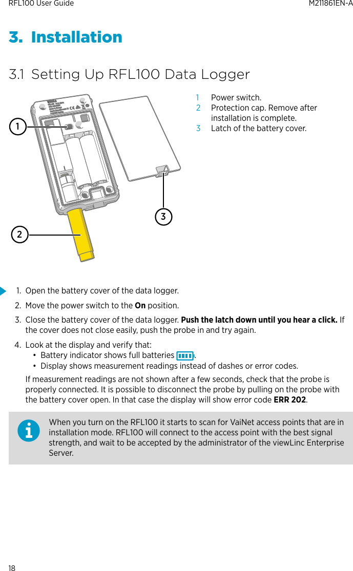
![3.2 Mounting RFL100A BDC68 [2.65]mm[in]Figure 7 RFL100 Mounting MethodsAMounting with screws. Screws and wall plugs are included with the data logger.BMounting with zip ties. Zip ties are included with the data logger.CMagnetic mounting (with optional magnetic mounting bracket)DMounting with a hook (hook not included)Chapter 3 – Installation19](https://usermanual.wiki/Vaisalaj/RFL100A/User-Guide-3853780-Page-21.png)
![4. Press the Menu button and select the Calibration submenu. 5. Select the parameter to be calibrated at menu item [1] Quantity. You can calibrateTemperature (T) or Relative Humidity (RH) measurement. All other humidity parametersare calculated from RH and T, so they will also be adjusted. RFL100 User Guide M211861EN-A26](https://usermanual.wiki/Vaisalaj/RFL100A/User-Guide-3853780-Page-28.png)
![6. Select the number of calibration points at menu item [2] Points. 7. Place the probe in the first reference environment (first calibration point). Wait 20 – 40minutes for the reading to stabilize.Chapter 4 – Maintenance27](https://usermanual.wiki/Vaisalaj/RFL100A/User-Guide-3853780-Page-29.png)
![8. Select menu item [3] Point 1 and press the Set button. The meter now shows thecurrently measured value of the selected parameter. Set the reference value using thearrow buttons and press the OK button. The correction to the measurement at point 1 is now shown in the text for menu item [3]Point 1. If you are only doing a 1-point calibration, skip to step 11.9. Place the probe in the second reference environment (second calibration point). Wait 20 –40 minutes for the reading to stabilize.RFL100 User Guide M211861EN-A28](https://usermanual.wiki/Vaisalaj/RFL100A/User-Guide-3853780-Page-30.png)
![10. Select menu item [4] Point 2 and press the Set button. The meter now shows thecurrently measured value of the selected parameter. Set the reference value using thearrow buttons and press the OK button. The correction to the measurement at point 2 is now shown in the text for the menu item[4] Point 2.Chapter 4 – Maintenance29](https://usermanual.wiki/Vaisalaj/RFL100A/User-Guide-3853780-Page-31.png)
![11. Select menu item [5] Note to edit the calibration info text that is stored in the probe. Editthe text using the select button and arrow keys. When done, select the OK character inthe bottom right corner to save the changed text. To exit without saving, press the Cancelbutton. 12. Select menu item [6] Apply to view the calibration result. Verify the applied corrections inthe confirmation screen and press the Apply button to apply the adjustment to the probe,or Cancel to exit without applying the adjustment. 13. Disconnect the probe from the HM40.14. Connect the probe to the RFL100 Data Logger. See Connecting the Probe (page 24).RFL100 User Guide M211861EN-A30](https://usermanual.wiki/Vaisalaj/RFL100A/User-Guide-3853780-Page-32.png)
![11. Perform the adjustment using a reference probe, perform these steps:a. Select To same as RH[II].b. To confirm the adjustment, select YES. If you select NO, you return to the adjustmentmode display and no changes are made.12. Calibration and adjustment is now completed. Select BACK to exit the adjustment modeand EXIT to return to the basic display.13. Disconnect the calibrated probe from the MI70 indicator.14. Reconnect the probe to the data logger. See Connecting the Probe (page 24).4.6 Changing RFL100 Batteries• 2 pcs of new AA size 1.5 V batteries: alkaline (type LR6) or lithium (type FR6)1. Remove the data logger from the mounting bracket.2. Open the battery cover of the data logger.3. Move the power switch to the O position.4. Remove the old AA size batteries from the data logger.5. Check the battery orientation markings on the data logger and insert the new batteries inthe correct orientation.6. Move the power switch to the On position.7. Close the battery cover of the data logger. Push the latch down until you hear a click. Ifthe cover does not close easily, push the probe in and try again.8. Insert the data logger back in the mounting bracket.4.7 Changing RFL100 Clock Battery• New 3 V lithium battery (type CR1/3N button cell)• Small flat-head screwdriver1. Open the battery cover of the data logger.2. Use a small flat-head screwdriver to lift the top part of the small plastic cover markedClock battery (CR1/3N), and slide the cover upward until it comes loose.3. Use the small screwdriver to lift the old clock battery from the battery socket.RFL100 User Guide M211861EN-A32](https://usermanual.wiki/Vaisalaj/RFL100A/User-Guide-3853780-Page-34.png)
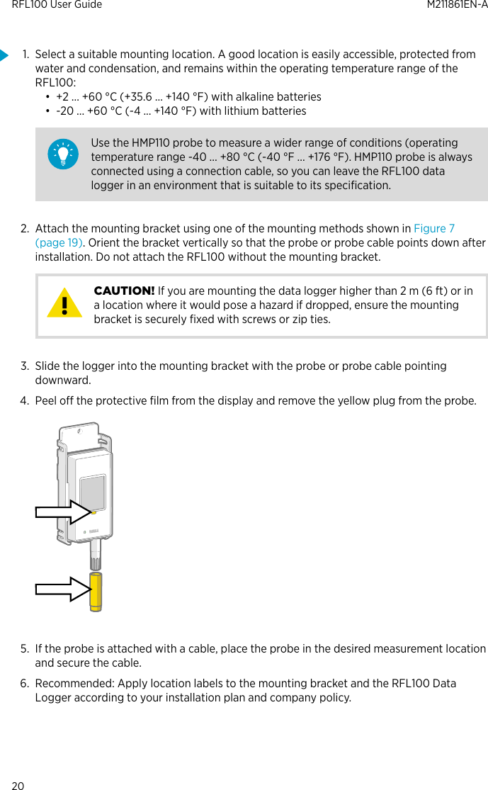
![6.5 RFL100 Dimensions68 [2.68]186 [7.32]36.5 [1.44]12 [0.47]mm[in]Figure 8 RFL100 Data Logger Dimensions with Mounting BracketRFL100 User Guide M211861EN-A46](https://usermanual.wiki/Vaisalaj/RFL100A/User-Guide-3853780-Page-48.png)
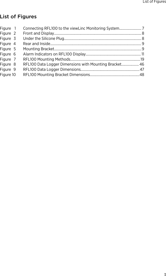
![158 [6.22]62 [2.4] 31 [1.22]12 [0.47]mm[in]Figure 9 RFL100 Data Logger DimensionsChapter 6 – Technical Data47](https://usermanual.wiki/Vaisalaj/RFL100A/User-Guide-3853780-Page-49.png)