ValenceTech IBT-0405 BLUETOOTH MODULE FOR AUDIO APPLICATION User Manual BC5MMFP B C 1120
ValenceTech Limited BLUETOOTH MODULE FOR AUDIO APPLICATION BC5MMFP B C 1120
UserManual.wiki
>
ValenceTech
>
IBT 0405 User Manual
User Manual
Navigation menu
Upload a User Manual
Namespaces
Wiki Guide
HTML
PDF
Info
Views
User Manual
Discussion / Help
Navigation
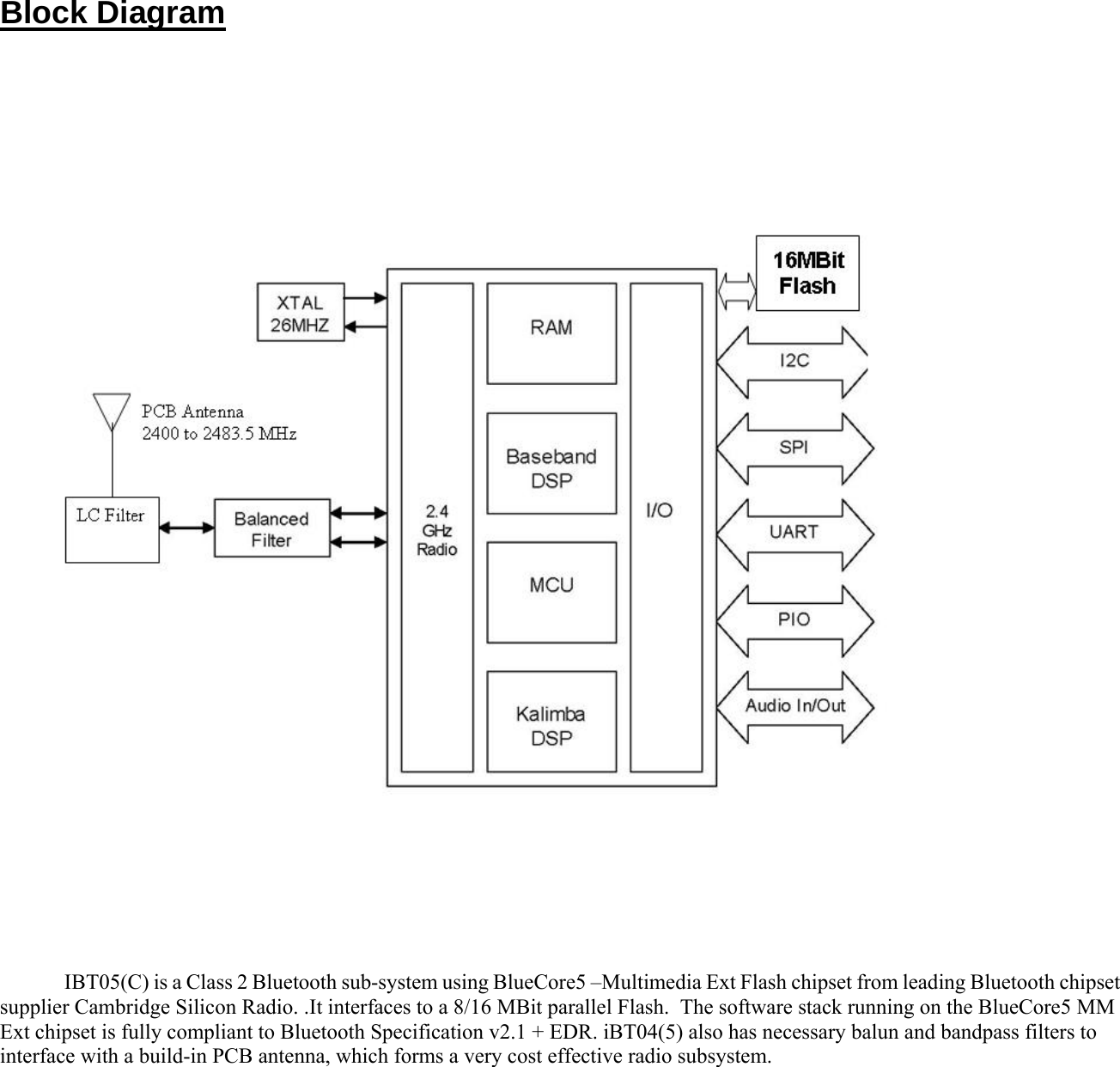
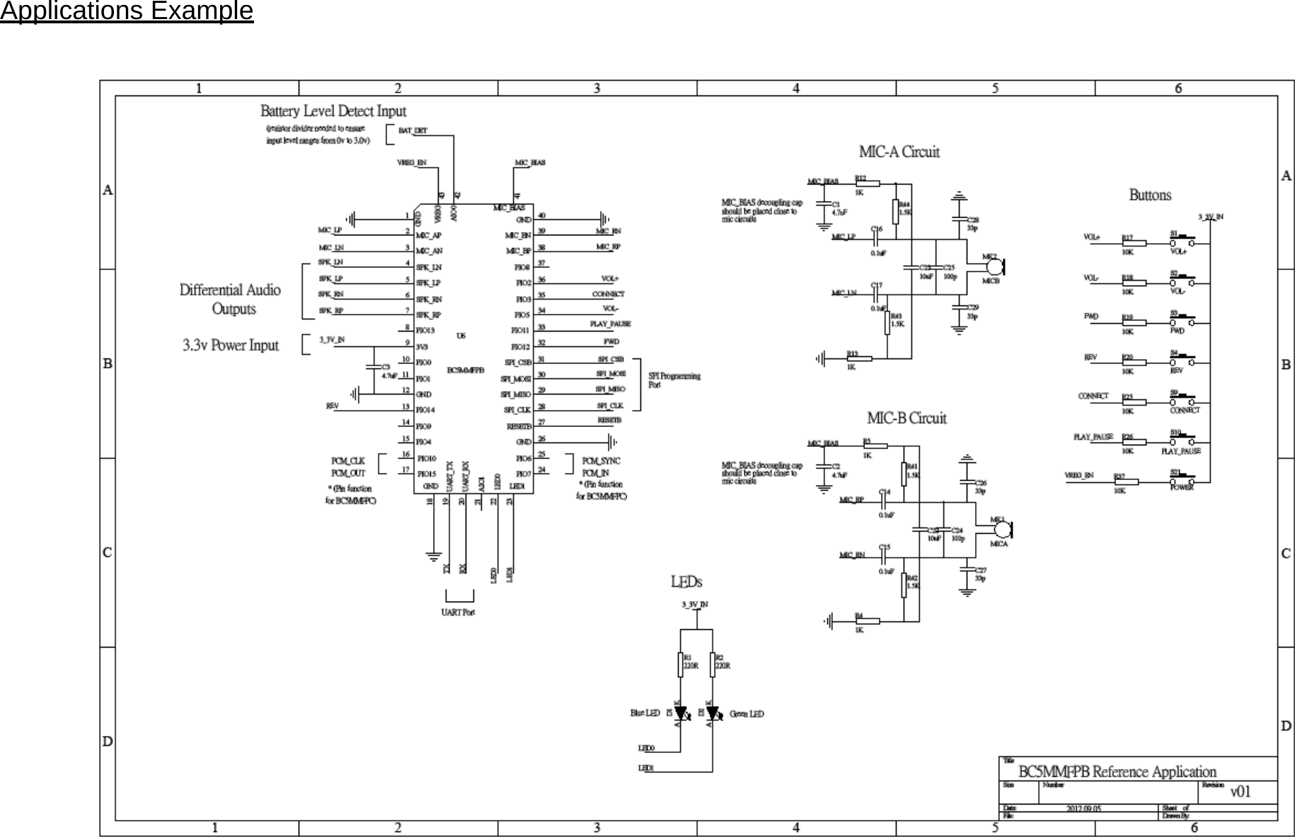
![IBT05 (C) includes 2 pads dedicated to driving LED indicators. Both terminals can be controlled by firmware, The terminals are open-drain outputs, so the LED must be connected from a positive supply rail to the pad in series with a current limiting resistor. It is recommended that the LED pad, LED[0] or LED[1] pins, operate with a pad voltage below 0.5V. In this case, the pad is like a resistor, RON . The resistance together with the external series resistor sets the current in the LED. Buttons The example application has assigned the following functions to each PIO pins: PIN NAME Function Descriptions 13 PIO14 REV Select previous song, fast rewind.32 PIO12 FWD Select next song, fast forward 33 PIO11 PLAY_PAUSE Play / pause toggle 34 PIO5 VOL- Volume increase 35 PIO3 CONNECT Switch to next connected device 36 PIO2 VOL+ Volume decrease 42 AIO(0) BAT_DET Battery level detection 43 VREG VREG_EN Power on, sleep mode FCC RF Exposure Requirement 1. At least 20cm separation distance between the antenna and the user’s body must be maintained at all times. And must not transmit simultaneously with any other antenna or transmitter, except in accordance with FCC multi transmitter product procedures. 2. To comply with FCC regulations limiting both maximum RF output power and human exposure to RF radiation, the maximum antenna gain including cable loss in a mobile-only exposure condition must not exceed 0dBi in the 2.4G band. 3. A user manual with the end product must clearly indicate the operating requirements and conditions that must be observed to ensure compliance with current FCC RF exposure guidelines. Please be noticed following information and instructions should be placed in the end-user’s operating manual The Module has been granted as limited modular approval for mobile applications. This Module must be installed in the designated host as specified in this manual. 1. Separate approval is required for all other operating configurations, including portable configurations with respect to 2.1093 and different antenna configurations. 2. The Module and its antenna must not be co-located or operating in conjunction with any other transmitter or antenna within a host device. This equipment complies with FCC RF radiation exposure limits set forth for an uncontrolled environment. 3. A label must be affixed to the outside of the end product into which the module is incorporated, with a statement similar to the following: For iBT05, iBT04: This device contains FCC ID: ORP-IBT-0405. 4. The module shall be in non-detachable construction protection into the finished products, so that the end-user has to destroy the module while remove or install it. 5. This module is to be installed only in mobile or fixed applications. According to FCC part 2.1091(b) definition of mobile and fixed devices is:. Mobile device: A mobile device is defined as a transmitting device designed to be used in other than fixed locations and to generally be used in such a way that a separation distance of at least 20 centimeters is normally maintained between the transmitter’s radiating structure(s) and the body of the user or nearby persons. In this context, the term ‘‘fixed location’’ means that the device is physically secured at one location and is not able to be easily moved to another location. Portable device: For purposes of this section, a portable device is defined as a transmitting device designed to be used so that the radiating structure(s) of the device is/are within 20 centimeters of the body of the user. 6. Separate approval is required for all other operating configurations, including portable configurations with respect to FCC Part 2.1093 and different antenna configurations. 7. A certified modular has the option to use a permanently affixed label, or an electronic label. For a permanently affixed label, the module must be labelled with an FCC ID: ORP-IBT-0405. The OEM manual must provide clear instructions explaining to the OEM the labelling requirements, options and OEM user manual instructions that are required](https://usermanual.wiki/ValenceTech/IBT-0405/User-Guide-1884153-Page-5.png)