Vanguard Creed Users Manual
2015-09-01
: Vanguard Vanguard-Creed-Users-Manual-804723 vanguard-creed-users-manual-804723 vanguard pdf
Open the PDF directly: View PDF ![]() .
.
Page Count: 8

Getting Started
QUICK START
VAN-ARV-CREED-QS-V1.02-26.0.2009
• The VANGUARD MARKER is not a toy.
• Careless or improper use, including failure to follow instructions and warnings within this Operator
Manual and attached to the VANGUARD MARKER could cause death or serious injury.
• Do not remove or deface any warnings attached to the VANGUARD MARKER.
• Paintball industry standard eye/face/ear and head protection designed specically to stop paintballs and
meeting ASTM standard F1776 (USA) or CE standard (Europe) must be worn by user and any person within
range.
• Must be at least 18 years of age to purchase the VANGUARD MARKER.
• Persons under 18 years of age must have adult supervision when using or handling the VANGUARD
MARKER.
• Observe all local and national laws, regulations and guidelines.
• Use only on professional paintball elds where codes of safety are strictly enforced.
• Use compressed air/nitrogen gas only. Do not use CO2.
• Do not exceed 850 psi (58 bar) input pressure.
• Always follow instructions, warnings and guidelines given with any rst stage regulator you use with the
VANGUARD MARKER.
• Use 0.68 calibre paintballs only.
• Keep the VANGUARD MARKER switched o until ready to shoot.
• Treat every marker as if it is loaded.
• Never point the VANGUARD MARKER at anything you do not intend to shoot.
• Do not shoot at persons at close range.
• Do not shoot at fragile objects such as windows.
• Always measure your markers velocity before playing paintball, using a suitable chronograph.
• Never shoot at velocities in excess of 300 feet (91.44 meters) per second, or at velocities greater than local
or national laws allow.
WARNING
OLED & BASIC MENU
06
QUICK START
VAN-ARV-CREED-QS-V1.02-26.0.2009
• Do not re the VANGUARD MARKER without the bolt in the breech, as high pressure gas will be
emitted.
• Do not re the VANGUARD MARKER with the bolt pin in the unlocked position.
• Never look into the barrel or breech area of the VANGUARD MARKER whilst the marker is switched on
and able to re.
• Never put your nger or any foreign objects into the paintball feed tube of the VANGUARD MARKER
• Never allow pressurised gas to come into contact with any part of your body.
• Always switch o the VANGUARD MARKER when not in use.
• Always t a barrel blocking device to your VANGUARD MARKER when not in use on the eld of play.
• Always remove all paintballs from the VANGUARD MARKER when not in use on the eld of play.
.• Always remove the rst stage regulator and relieve all residual gas pressure from the VANGUARD
MARKER before disassembly.
• The VANGUARD MARKER can hold a small residual charge of gas, typically 2 shots, with the rst stage
regulator removed. Always discharge the marker in a safe direction to relieve this residual gas pressure.
• Always remove rst stage regulator and all residual gas pressure from the
VANGUARD MARKER for transport and storage.
• Always follow warnings and guidelines given with your rst stage regulator for safe transport and storage.
• Only charge the VANGUARD MARKER using the charger supplied.
• Do not leave the VANGUARD MARKER unattended whilst charging.
• Always store the VANGUARD MARKER in a secure place.
• THIS OPERATOR MANUAL MUST ALWAYS ACCOMPANY THE PRODUCT IN THE EVENT OF
RESALE OR NEW OWNERSHIP.
• SHOULD YOU BE UNSURE AT ANY STAGE YOU MUST SEEK EXPERT ADVICE.
WARNING
Turning the Marker on
To turn the marker on, hold the Power/ENTR button until the home screen (g 1.)
appears on the display in the left hand side of the grip. At this point the marker
is powered on and ready to re.
Turning the Marker o
To turn the marker o, hold the Power/ENTR button to enter the menu, and
then push the Power/ENTR option again on the rst item in the Main Menu,
“Power O.”(g 2.) The marker will shut down when this function is selected.
QUICK START
Charging the Marker
The battery level is displayed in the top left corner of the home screen (g 3.);
when this gets low (g 4. (a,b & c ) you should recharge the marker with the pro-
vided charger.
You may also charge the marker from any USB host (such as laptop computer,
etc.) although the charge rate will be slower.
The dedicated wall charger typically takes about 60-90 minutes to fully charge
a low battery; other USB devices will only fully charge the marker in about 6
hours.
To Gas up the Marker
The CREED™ comes equipped with an ON/OFF/PURGE ASA attached to the
bottom of the frame.
To turn on the gas supply, twist the ON/OFF knob clockwise, all the way in. To
turn o the gas supply, twist the ON/OFF knob counterclockwise, all the way
out.
As you turn the knob out, the residual gas between the HPR and the ON/OFF
airport is vented. Always re o to empty marker once degassed, this can be
done by holding the trigger in for more than 1 second.
g 1.
g 2.
g 3. g 4a. g 4b. g 4c.
Indicating maker is plugged in and charging.
VAN-ARV-CREED-QS-V1.02-26.0.2009
OLED & BASIC MENU
06
The OLED Display
The marker incorporates a full-colour Organic LED (OLED) display, providing an
instant visual indication of the marker’s status and an easy means of adjusting
the marker’s settings. When the marker is turned on, and during normal use,
the home screen is visible on the display. The home screen displays several
items of useful information; notably the battery level, current re mode, and
eye status indicator. The battery level indicator also shows when the marker is
being charged.
Using the Menus
Settings and information are available through an easy to use menu tree, mak-
ing use of the full colour screen built into the marker. To enter the menus, hold
the Power/ENTR button for a second. Once in the menu, navigate using the
Up and Down buttons, and select options with the Power/ENTR button. If you
need to change a setting a long way from its current setting, hold down the Up
or Down button for a while and the button will autorepeat, saving you from
continuous button pushing. Some options enter submenus; to get out of the
menus scroll to the “Back” option and select it. To exit the menus and return to
the home screen, scroll to the “Exit Menu” option in the main menu.
When the tournament lock is engaged, some functions cannot be selected;
these are marked with a padlock symbol. To access these functions, turn o the
tournament lock (see below.)
Tournament Lock
The marker features a tournament lock function which allows certain settings,
which could aect how the marker res, to be disabled. This ensures that once
a marker has been set up within the rules of a tournament, it cannot be modi-
ed to increase velocity, rate of re, or engage enhanced re modes, without
the use of tools.
To change the setting of the tournament lock, insert a pointed object such as a
paper clip or small allen key through the hole below the USB port. A “Tourney
Lock” menu will appear on the screen, which allows you to turn the lock on or
o. Conrm your selection with the Power/ENTR button.
To turn eyes o & on
The Marker default settings automatically turn the eyes on, to switch o hold
the top button/UP until you see a blue line in a semi circle on display (g 5a.)
To turn back on press top button/UP until 2 red semi circles are displayed
(g 5b.), note if you move the bolt forward a green dot will appear indicating a
ball in the breach (g 5c.).
Menu Map
Main Menu / Power O / Fire Mode / Preset / Max ROF / Eye o ROF / ROF Cap
Ramp Cong / Ramp Start / Ramp Stop / Ramp Reset / Semi Shots / Max
Burst / Back / Back
Settings / Dwell / Debounce / Eye Delay / Eye Sens. / Bolt Delay / Clearing
Shot / FSDO Time / FSDO Dwell / Reset All / Back
Info
Exit Menu
QUICK START
HPR (high pressure regulator) ADJUSTMENT
The HPR is adjustable from 0- 300psi and is factory set to around 180psi.
To adjust the pressure DOWN turn the adjuster CLOCKWISE 1⁄4 turn at a time
then re the marker to see if your change is as desired (g 6a.).
To adjust the pressure UP turn the adjuster ANTI CLOCKWISE 1⁄4 turn at a
time then re the marker to see if your change is as desired (g 6b.).
LPR (low pressure regulator) ADJUSTMENT
The LPR is adjustable from 0- 120psi and is factory set to 90psi.
To adjust the pressure DOWN turn the adjuster ANTI CLOCKWISE 1⁄4 turn at a
time then re the marker to see if your change is as desired (g 6a.).
To adjust the pressure UP turn the adjuster CLOCKWISE 1⁄4 turn at a time then
re the marker to see if your change is as desired (g 7b.).
g 5a. g 5b. g 5c.
CLOCKWISE =
PRESSURE DOWN
0-300 PSI
CLOCKWISE =
PRESSURE UP
0-120 PSI
ANITCLOCKWISE =
PRESSURE UP
0-300 PSI
CLOCKWISE = PRESSURE DOWN (0-300 PSI) ANTI CLOCKWISE = PRESSURE UP (0-300 PSI)
CLOCKWISE = PRESSURE UP (0-120 PSI)
g 6a. g 6b.
g 7b.
ANTI CLOCKWISE = PRESSURE DOWN (0-120 PSI)
g 7a.
VAN-ARV-CREED-QS-V1.02-26.0.2009

Problems & Solutions
Problems and Solutions
Problem: The creed will not turn on
Solution: Check battery is plugged in correctly and it has been charged the
board may be faulty.
(Go to vanguardpaintball.com support section or email tech@vanguardpaintball.com
if the problem persists)
Problem: There are leaks coming from the solenoid
Solution: Check the rammer sail o-ring 009.
Check the gasket o-rings.
Cause: The LPR 15 x2 o-rings may be damaged change them both and the
Schrader could be failing.
The solenoid may be damaged.
Problem: Leaks down the barrel
Solution: Poppet valve may be dirty or damaged.
200-010 ni70 o-ring could be damaged.
The front o-ring 200-016 ni70 could be damaged.
Problem: Leaks from the back of the valve assembly
Cause: 200-008 ni70 o-ring may be damaged.
Problem: Bolt sticks forward
Cause: LPR pressure is too low.
Ramer sail o-ring 200-011 ni70 is damaged.
The internal 200-611 ni70 o-ring is damaged.
The Solenoid is damaged.
Input pressure from the HPR is too low.
Problem: Velocity too low
Solution: Check your HPR pressure is not too high, turn all the way in then turn
it out one and a quarter turns.
Cause: LPR pressure set too low.
Front dwell too low.
Problem: Velocity spiking
Solution: LPR pressure set too low.
Front dwell too low.
HPR needs cleaning and servicing.
The HPR is set too high.
LPR needs cleaning and servicing.
Cause: Battery low.
O-rings 200-009 ni70 and or 200-008 ni70 o-ring is damaged on the
back of the poppet valve.
The sail 200-011 ni70 o-ring on the rammer is damaged.
The 200-611 ni70 internal o-ring is damaged on the rammer housing
Check the valve plug has not come loose.
Problem: Leaks from the hole on the side of the HPR
Cause: O-rings 200-010 ni70, 10x2 ni70 and the 200-016 o-rings are dam aged
Problem: Leaks from the bottom of the HPR
Solution: O-rings 2 o 200-801 ni70 and or the 3 o 200-016 ni70 (change and
put a small amount of grease on them before reassembling)
VAN-ARV-CREED-QS-V1.02-26.0.2009
Problems & Solutions
Problem: Bolt not cycling
Cause: Pin not been pushed in properly pull out and push back in.
Problem: Air leaks from the back of the valve body or back of the marker
Solution: This may be caused by the 200-013 ni70 o-ring or the 200-611 ni70
o-ring being damaged. You can test for this by taking the LPR pressure
the o-rings. Put a small amount of grease on the valve body when
reassembling the valve and be careful not to damage the
o-rings when putting the valve body back into the marker.
Problem:
Cause: This will be caused by the top feed not being screwed on tight enough
Problem: Air coming from the elbows
Solution: This is caused when the elbows have not been screwed down enough;
tighten them up with a spanner until the leaks have sealed
Problem: Air coming from the ASA
Solution: Air Coming from the ASA 200-015 ni70 bottle o-ring which are
attached on the bottle itself.
The 200-004 ni70 o-ring situated on the inside of the ASA could be
damaged, replace o-ring.
The two holes that let the air through are very close. Make sure there
is no damage on the face between these two holes as this can cause a
small leak.
Problem:
Solution: Trigger not adjusted correctly (adjust trigger until it operates the
micro switch)
The wires inside may have become between the micro switch and the
trigger (tuck wires away from the switch)
The solenoid plug may have come loose (push the plug in)
HPR regulator not set correctly (adjust)
LPR not set correctly (adjust)
Battery low (charge marker)
Solenoid not working (replace solenoid)
Board gone down (replace)
Problem: Leak from the front of the LPR
Solution: Change piston o-ring 200-012 ni70
Problem: Leak from the transfer LPR line
Solution:
Check pipe for splits or damage especially around the barbs
To start from scratch with the LPR & HPR
Tip: As a general rule of the thumb, start with the HPR adjuster fully in, then
wind the HPR adjuster out by 1 - 1 1/3 turns.
For the LPR adjuster, start with it fully out and then wind in while
ring the marker until it cycles, then adjust to get desired velocity
over a chronograph.
If it sounds gassy in cycle, it could be that the LPR is too low or the dwell
setting is to high, this will change as your marker beds in so will require
readjustment to maintain.
VAN-ARV-CREED-QS-V1.02-26.0.2009
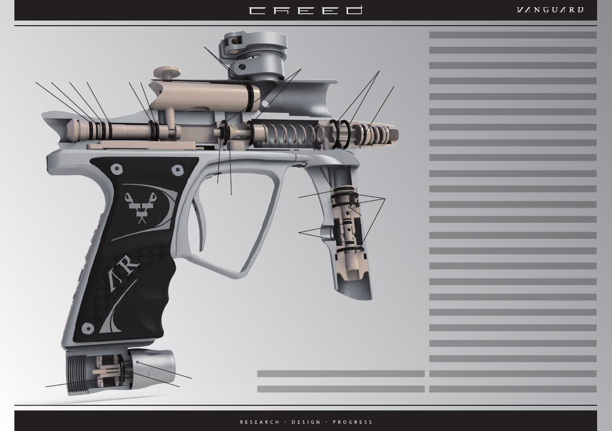
Part list
VAN-ARV-CREED-QS-V1.02-26.0.2009
2a. Cre212 Ram Back Guide O Ring 200-011 Ni70
2b. Cre211 Ram Front Bumper O Ring 200-009 Ni70
3. Cre217 Bolt Pin
4. Cre215 Delrin Bolt
4a. Cre219 Bolt O Ring 200-014 Ni70 X 2o
5. Cre204 Valve Body
5a. Cre207 Valve Body Ext Tail O Ring 200-806 Ni70
5b. Cre208 Valve Body Int Tail O Ring 200-611 Ni70
5c. Cre206 Valve Body Front Int O Ring 200-008 Ni70
5d. Cre205 Valve Body Front Ext O Ring 200-014 Ni70 X 2 o
6. Cre232 Poppet
6a. Cre203 Poppet Tail O Ring 200-010 Ni70
7. Cre223 Manifold
8 Cre800 Trigger Frame
9. Cre821 Rubber Grip
10. Cre801 Trigger
11. Cre221 Valve Body Retainer
12. Cre222 Valve Spring
13. Cre501 Feedneck Clamp Ring
14. Cre500 Feedneck Body
15. Cre502 Feedneck Lever
16. Cre503 Feedneck Collet
17. Cre108 Lpr Locating Pin
18. Cre301 Lpr Core
18a. Cre308 Lpr Core Outer O Ring 15 x 2 Ni70 X 2 o
19. Cre306 Schrader Core 9914A
20. Cre302 Lpr Piston
20a. Cre303 Lpr Piston O Ring 200-012 Ni70
21. Cre305 Lpr Spring LC072G02M
22. Cre304 Lpr Adjuster
23. Cre300 Lpr cap
24. Cre106 Hpr Body (015 O Ring to Main Body)
25. Cre700 Hpr Piston
25a. Cre707 Hpr Piston O Ring 10 x 2 Ni70
26. Cre702 Hpr Core
26a. Cre709 Hpr Core Ext O Ring 200-016 Ni70 X 3 o
26b. Cre708 Hpr Core Int O Ring 200-010 Ni70
27. Cre701 Hpr Adjuster
27a. Cre711 Hpr Adjuster O Ring 200-801 Ni70 X 2 o
28. Cre401 Asa Cap
29. Cre402 Asa Core
29a. Cre403 Asa Core O Ring 200-015 Ni70
29b. Cre407 Asa Core Front O Ring 200-005 Ni70
30. Cre400 Asa Main Body
31. Cre404 Cross Pin
31a. Cre405 Cross Pin O Ring 200-004 Ni70 X 2
32. Cre225 Transfer Barb (not shown)
32a. Transfer Barb O Ring 200-005 Ni70 X 2
12
25
1. Cre210 Ram Cap
1a. Cre214 Ram Cap Outer O Ring 200-011 Ni70
1b. Cre213 Ram Cap Bumper O Ring 200-008 Ni70
2. Cre209 Rammer
31
1a 1b 2a 2b 5a
21
5b
7
8
4
3
56
11
4a
13
14
15
5d 18a
20a
24
26
27
10
25a
27a
26a
26a
28
30 29
29b
31a
29a
5c
6a
18
9
22
23
20 21
19
17
16
