Vantage Controls RDS1000 Home automation transmitter User Manual RF Station Dimmer Instructions
Vantage Controls Inc. Home automation transmitter RF Station Dimmer Instructions
manual with RF
1
VANTAGE Installation
1061 SOUTH 800 EAST • OREM, UTAH 84097 • TELEPHONE 801.229.2800 • FAX 801.224.0355 • WEBSITE www.vantageinc.com
RDSx Dimmer
Station
Overview
The Vantage RF Dimmer Station is a wall box dimmer that
connects to the Vantage Control System. It is available in 1-4
load configurations that can be mounted respectively in 1-4
gang back boxes. It is powered via the local line feed, and
communicates with the system through a radio transceiver.
Before the dimmer is programmed, or if communication is lost,
the dimmer functions in default mode as an independent
dimmer. Once a button is programmed it can perform any
operation that a standard station supports controlling its own or
other loads. Any load on the dimmer can be controlled by any
other keypad, IR input or timed event. It supports up to eight
keypad buttons, and an optional internal IR receiver.
System Requirements
Master Controller firmware version 5.92 or higher and
Q-Link software version 3.10 or higher is required for proper
operation.
Minimum Back Box Dimensions
Number of Gangs Minimum Back Box Dimensions
1 2.80”h x 1.80”w x 2.5”d
2 2.80”h x 3.60”w x 2.5”d
3 2.80”h x 5.40”w x 2.5”d
4 2.80”h x 7.20”w x 2.5”d
With these dimensions most standard back boxes that have
the receiving threads for the Dimmer mounting screw inside
the box will be adequate. Most back boxes where the receiving
threads are outside the box will be too small.
Load Ratings
Number of Gangs Maximum Rating at 120V 60Hz
1 5A, 600W
2 8.3A, 1000W
3 12.5A, 1500W
4 16.7A, 2000W
No individual load can exceed 5A, 600W.
The RF Dimmer Station is for control of incandescent or
low voltage magnetic lamp fixtures only.
This unit shall be provided with a maximum of 30 Amps
non-time delay suitable branch circuit protection.
CAUTION: To reduce the risk of overheating and possible
damage to other equipment, do not install to control a
receptacle or a motor-operated appliance.
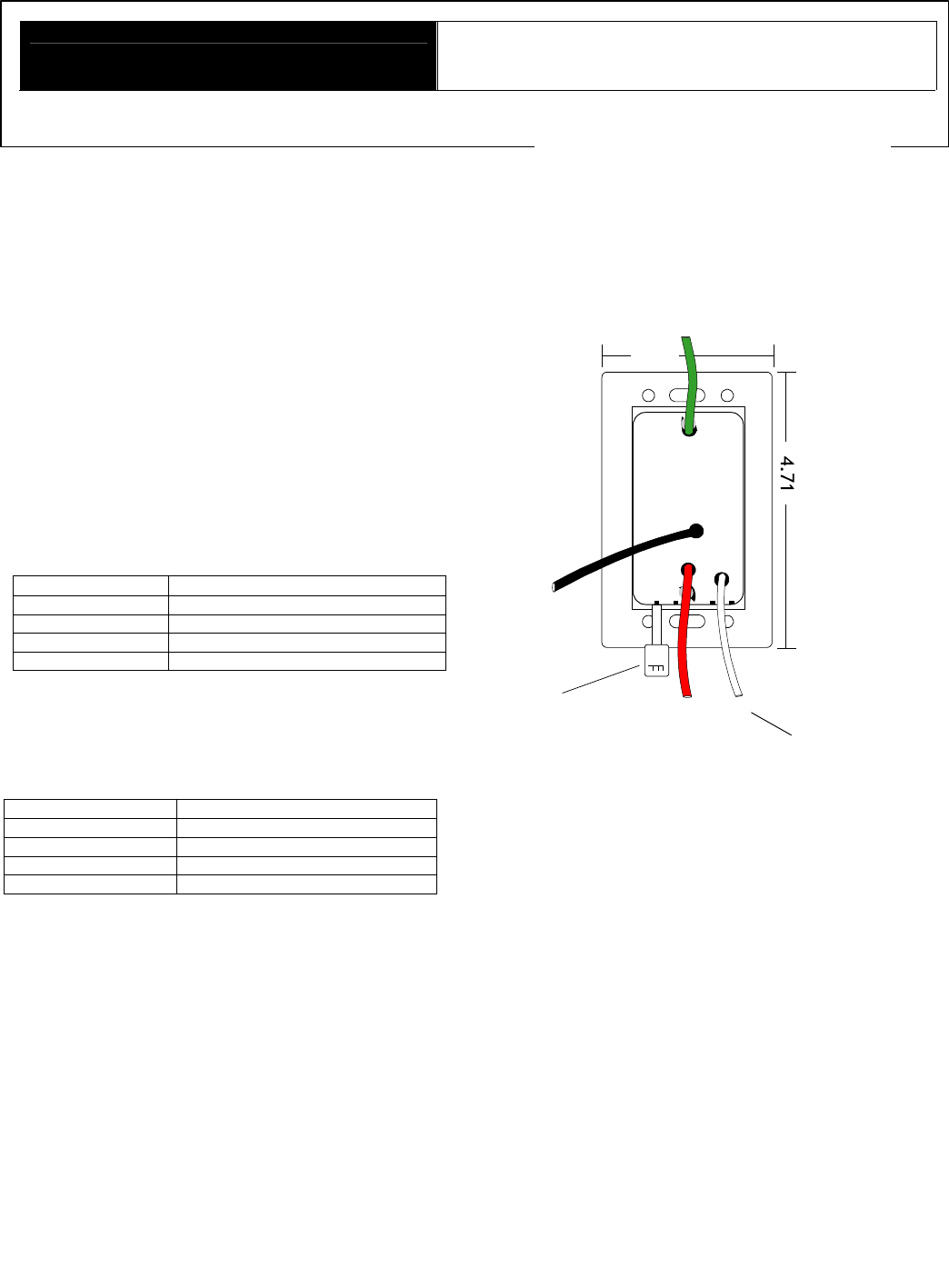
Installation
Turn the circuit breaker off and make sure no voltage is
present where the RF Dimmer Station is mounted. Damage
caused by failure to disconnect power may avoid warranty and
is a risk to the installer. In its standard configuration, the RF
Dimmer Station requires Neutral to operate. If operation
without Neutral is required, a non-Neutral stations must be
specified when ordering. When installing a station without
Neutral, the highest wattage load should be connected to the first
gang. The Green ground lead must be connected to the
structures safety ground.
White
(Neutral)
Red
(Load Out)
Black
(Line In)
Green
(Ground)
Safety
Switch
2.95
Dimmer Station Set Up with Q-link
To add an RF Dimmer Station in Q-Link, right click on the room
and from the pop-up menu, select Add Station/Dimmer from the
station list. This will reveal the Dimmer Station Definition Box.
Select the number of buttons and loads according to the
configuration of your dimmer station and click OK. Right click on
the button you are programming and select Program. This will
reveal the Event Programming Dialog Box. Complete the
programming by selecting the desired Sta. Loads, functions and
conditions.
Configuration
The RF Dimmer Stations need to be configured to associate
which physical station goes with the station in Q-link.
When the Dimmer Station is initially powered-up, the Status LED
will blink twice followed by a pause - this means the station is
connected correctly but not yet configured. From the menu bar in
Q-Link, select System/Configure Stations. A list of all stations will
be displayed on the screen. Select the RF Dimmer Station press
the Configure radio button in the Online Configuration section of
the window. Enter the serial numbers of all RF Dimmer Stations
to configure them. The Status LED will blink steadily when a
station is configured.
2
Service Switch
An off switch is provided to disconnect power between the
Station and the fixture for lamp replacement. Service other
than lamp replacement requires the breaker to be switched off.
Default Mode
The RF Dimmer Station has a default mode that operates
without programming or being connected to the Vantage
System. If a Dimmer has been programmed but
communication with the controller is lost the Dimmer will revert
to default operation. Multiple gang Dimmers loads are
numbered from left to right.
Station Type Button to Load Mapping
1-gang Dimmer All buttons control the one
load.
All buttons in first (left) gang.
One column of buttons
The top button controls
first load.
Second button controls
second load etc.
All buttons in first gang.
Two columns of buttons.
Top left button controls
first load.
Top right button controls
second load.
Second row left button
controls third load.
Second row right button
controls fourth load.
One or two buttons
per gang. Each button(s) controls the
load in its gang.
When default is the desired operation for a button, it can be left
unprogrammed and will continue to operate in default mode
even if other buttons on the dimmer are programmed.
When power is restored from a power outage the Dimmer will
return the loads to the last load level. This will occur whether
or not the Dimmer is connected to a system.
Default Operation
Button
Action Load Operation
Single
Press
The load toggles between off and the learned
level. The turn on ramp time is 1.5 seconds
and the turn off fade time is 5 seconds.
Double
Press
The load ramps to 100% in 1.5 seconds. The
second press must be within 1 second of the
first press.
Press and
Hold
After a one second delay the load will ramp in
the opposite direction from the last press and
hold. If the load reaches 0 or 100% it will
reverse direction. When the button is released
the current load level will be saved as the new
learned level for that button. The cycle time is
5 seconds from 0-100%.
When multiple buttons control the same load, each button will
have its own learn level.
Default IR Mode
If the Dimmer has the optional IR receiver, the Dimmer will
have a default IR mode that is active when the RF Dimmer
Station is not communicating with a system or when none of
the Scene Codes in its IR Zone have been programmed.
The Scene Codes 230-239 are transmitted by the Scene
buttons 1-10 on the Vantage IR Remote Control.
The Scene buttons 1-4, codes 230-233, controls loads 1-4
operating the same as the default operation for a button.
Scene 9, code 238, will turn all station dim
mer loads on. Scene
10, code 239, will turn all station dimmer loads off.
Unlike the buttons, if any IR Scene button is programmed all of
the IR Scene buttons stop executing default operation.
Reset
The Dimmer stores the configuration data locally so that it will
continue to operate correctly if communication with the system
is lost. This information includes: LED properties, sounder
properties, load profile, last load level, and default learn levels.
To reset this information to the factory default, press and hold
switches 1-3 when power is applied to the station. The board
will respond by sounding three slow beeps to indicate that the
reset took place. Since buttons do not need to be installed in
switches 1-3, the faceplate may need to be removed so that
the switch matrix can be pressed directly.
After a reset the load profile will be Default, the learn levels will
be 50%, the loads will all be off, and other settings will be at
factory default.
Diagnostic Information
If the faceplate is removed the Status LED can be seen in the
approximate middle of the station’s switch matrix. The Status
LED blinks evenly or flashes 2, 3, 4 or 5 times followed by a
pause to indicate status information.
Off: The station is not powered. A line voltage connection has
not been made or the line feed breaker is off.
Even blink: Station is operating correctly and is configured.
Two blinks: Station is operating correctly but is not
configured.
Three blinks: Station is not communicating with the Master
Controller. Verify that station bus wiring conforms to Vantage
guidelines.
Four blinks: Dimmer problem. Please contact the factory.
Five blinks: Configuration mode.
FCC ID: PII-RDS1000
This device complies with Part 15 of the FCC Rules. Operation is
subject to the followin
g two conditions: (1) This device may not cause
harmful interference, and (2) this device must accept any interference
received, including interference that may cause undesired operation.
NOTE: This equipment has been tested and found to comply with the
limits for a Class B digital device, pursuant to Part 15 of the FCC
Rules. These limits are designed to provide reasonable protection
against harmful interference in a residential installation. This
equipment generates, uses and can radiate radio frequency
energy and,
if not installed and used in accordance with the instructions, may cause
harmful interference to radio communications. However, there is no
guarantee that interference will not occur in a particular installation. If
this equipment does cause harmful interference to radio or television
reception, which can be determined by turning the equipment off and
on, the user is encouraged to try to correct the interference by one or
more of the following measures:
-- Reorient or relocate the receiving antenna.
-- Increase the separation between the equipment and receiver.
-- Connect the equipment into an outlet on a circuit different
from that
to which the receiver is connected.
-- Consult the dealer or an experienced radio/TV technician for
help.
Changes or modifications to this product not expressly approved by
Vantage Controls could void the user’s authority to operate this
product.