Vantage Controls S232RF Home automation transmitter User Manual S232RF Instructions
Vantage Controls Inc. Home automation transmitter S232RF Instructions
manual for installation
VANTAGE Installation
1061 SOUTH 800 EAST •OREM, UTAH 84097 • TELEPHONE 801.229.2800 • FACSIMILE 801.224.0355 • WEBSITE www.vantageinc.com
S232RF
–
RadioLink
RS232 Station
System Requirements
RF enabled Master Controller.
Master Controller firmware version 5.92 or higher.
Qlink software version 3.1 or higher.
Overview
The S232RF connects RS232 devices to the Vantage System
via a wireless link. The Vantage Q-System can then be
programmed to control the connected devices, or vice versa.
Mounting
The RadioLink RS232 Station is connected to the equipment it
will be interfacing with. The small package will fit into most
enclosures, or hang behind the equipment.
IMPORTANT: In order to comply with the FCC RF exposure
requirements, this product must be installed and operated in
such a way that a minimum separation distance of 20 cm
(approximately 8 inches) is maintained from the antenna to any
persons. Operations that do not meet these requirements must
be avoided.
Station Connection
The RadioLink RS232 Station requires an external power supply
of +9VDC to +12VDC. This connection is made to the screw
terminal block provided. The station also has a power supply
output on the terminal block to allow other devices to be daisy-
chained from a single power supply. The RS232 signal
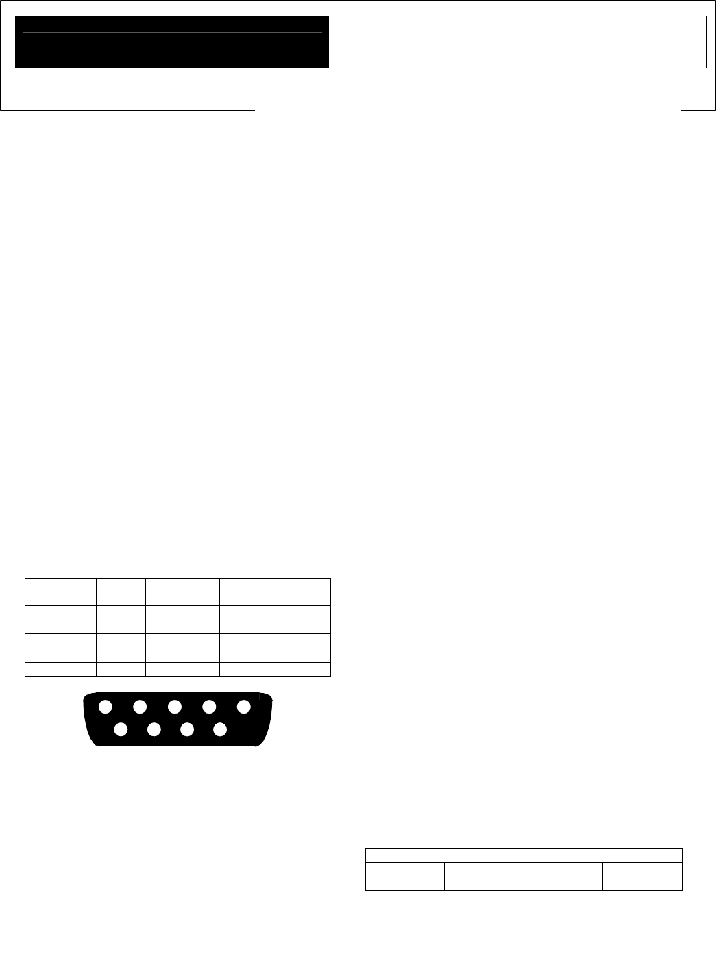
connections on the DB9 connector are detailed below.
S232RF DB9 Connector Signal Summary
Signal
Name DB9
Pin Wire Color Description
RX 2 Brown Data Out
TX 3 Red Data In
GND 5 Yellow Ground
CTS 7 Blue Handshake Out
RTS 8 Violet Handshake In
6789
12345
DB9 Connector
Using the S232RF for System Programming.
Once connected to the Vantage System, the RS232 Station is
ready to be connected to a PC and used to change system
programming with QLink. Connect between a PC and the Q-
RS232S with a 9-pin male to 9-pin female straight through
RS232 cable.
S232RF Set up with Qlink
In the Station Hierarchy Dialog box, select the floor and room
you would like to add the RadioLink RS232 Station to. In the
Station Type list box select RadioLink RS232. Then click Create
Next Level. The RadioLink RS232 Station Dialog Box will pop
up, allowing the communication settings to be defined. Select the
options for Baud Rate, Parity, the number of data and stop bits and
the type of handshaking if any. With the RS232 Station defined, it
can now be the used to transmit and receive RS232 Strings.
When you program a button and select RS232 function, the RS232
Station will be an option as a destination.
Using the RS232 function
The S232RF can be used to send commands to another RS-232
device using the RS232 function. Instead of selecting a master
RS-232 port from the RS232 Function dialog box, select a
RadioLink RS232 station that has been previously defined.
Using V commands
V commands are ASCII commands received from an RS232 port
that can control or get status information on the connected Q-
system. Any V command can be received and executed from an
S232RF. The S232RF does not need to be configured for this to
work. A complete list of V commands is available in the Qlink on-
line help.
Configuration
When the S232RF is first powered on, the diagnostic LED will blink
twice followed by a pause. This means the RS232 Station is
connected correctly but is not configured. It is configured like any
other RadioLink station. From Qlink, Select Define->Configure
Stations menu and select the Configure button. Enter the serial
number of the RadioLink RS232 Station to allow it to join the
network. The diagnostic LED will now blink evenly.
Diagnostic Information
The Diagnostic LED blinks 1, 2, 3, 4, 5, or 6 blinks followed by a
pause.
One Blink: S232RF is operating correctly and is configured.
Two Blinks: S232RF is operating correctly but is not configured.
Three Blinks: S232RF not communicating with the Master
Controller. Please contact the factory.
Four Blinks: Factory problem. Please contact the factory.
Five Blinks: The S232RF is waiting to be configured.
Six Blinks: Factory problem. Please contact the factory.
Hints
Connecting two RS232 Ports with a Voltmeter With the two
ports powered on, but not connected, take a Voltmeter and put the
ground probe in pin 5 and then measure the voltage on pins 2 and
3 on both ports. One pin will have around –10V and the other will
be close to 0 volts. Having done that on both ports, match up
Voltage to Non-voltage for both pin pairs. If you need hardware
hand shaking, then repeat this same procedure on pins 7 and 8.
Example: Here are the results of measuring the voltages one both
ports: RS232 Port 1 RS232 Port 2
Pin 2 -11 V Pin 2 -0.4 V
Pin 3 0.1 V Pin 3 -10 V
In this case Port1 Pin 2 would connect to Port 2 Pin 2 and Port 1
Pin 3 would connect to Port 2 Pin 3.
Using Q-RS232S with Qlink. If the Q-RS232S is being used to
download programming and the Q-RS232S is being redefined

(Baud rate, parity, handshaking changed) the download will hang
when th
is new information is sent to the master. The same is true
if on-line changes are being made, any on-line changes to the Q-
RS232S that is being used to communicate with the system can
cause the communications with Qlink to hang. Most often the Q-
RS232S should be left unconfigured if is being used with Qlink.
Memory Allocation on the Master. Each RS232 station will use
1200 bytes of memory on the master controller.
FCC ID: PII-S232RF
This device complies with Part 15 of the FCC Rules. Operation is
subject to the follow
ing two conditions: (1) This device may not cause
harmful interference, and (2) this device must accept any interference
received, including interference that may cause undesired operation.
NOTE: This equipment has been tested and found to comply with th
e
limits for a Class B digital device, pursuant to Part 15 of the FCC
Rules. These limits are designed to provide reasonable protection
against harmful interference in a residential installation. This
equipment generates, uses and can radiate radio frequen
cy energy and,
if not installed and used in accordance with the instructions, may cause
harmful interference to radio communications. However, there is no
guarantee that interference will not occur in a particular installation. If
this equipment does cause harmful interference to radio or television
reception, which can be determined by turning the equipment off and
on, the user is encouraged to try to correct the interference by one or
more of the following measures:
-- Reorient or relocate the receiving antenna.
-- Increase the separation between the equipment and receiver.
-- Connect the equipment into an outlet on a circuit different
from that
to which the receiver is connected.
-- Consult the dealer or an experienced radio/TV technician for
help.
Changes or modifications to this product not expressly approved by
Vantage Controls could void the user’s authority to operate this
product.