Varex Imaging Deutschland XRPAD 802.11n 3T3R Mini PCIe Module User Manual XRD 1622 AP3 Digital X Ray Detector
PerkinElmer Medical Imaging 802.11n 3T3R Mini PCIe Module XRD 1622 AP3 Digital X Ray Detector
Contents
- 1. User Manual.pdf
- 2. Users Manual XRPad 4336 MED
- 3. Users Manual XRPad 4336
- 4. Users Manual XRPad 4336 MED.pdf
- 5. Users Manual XRPad 4336.pdf
Users Manual XRPad 4336.pdf
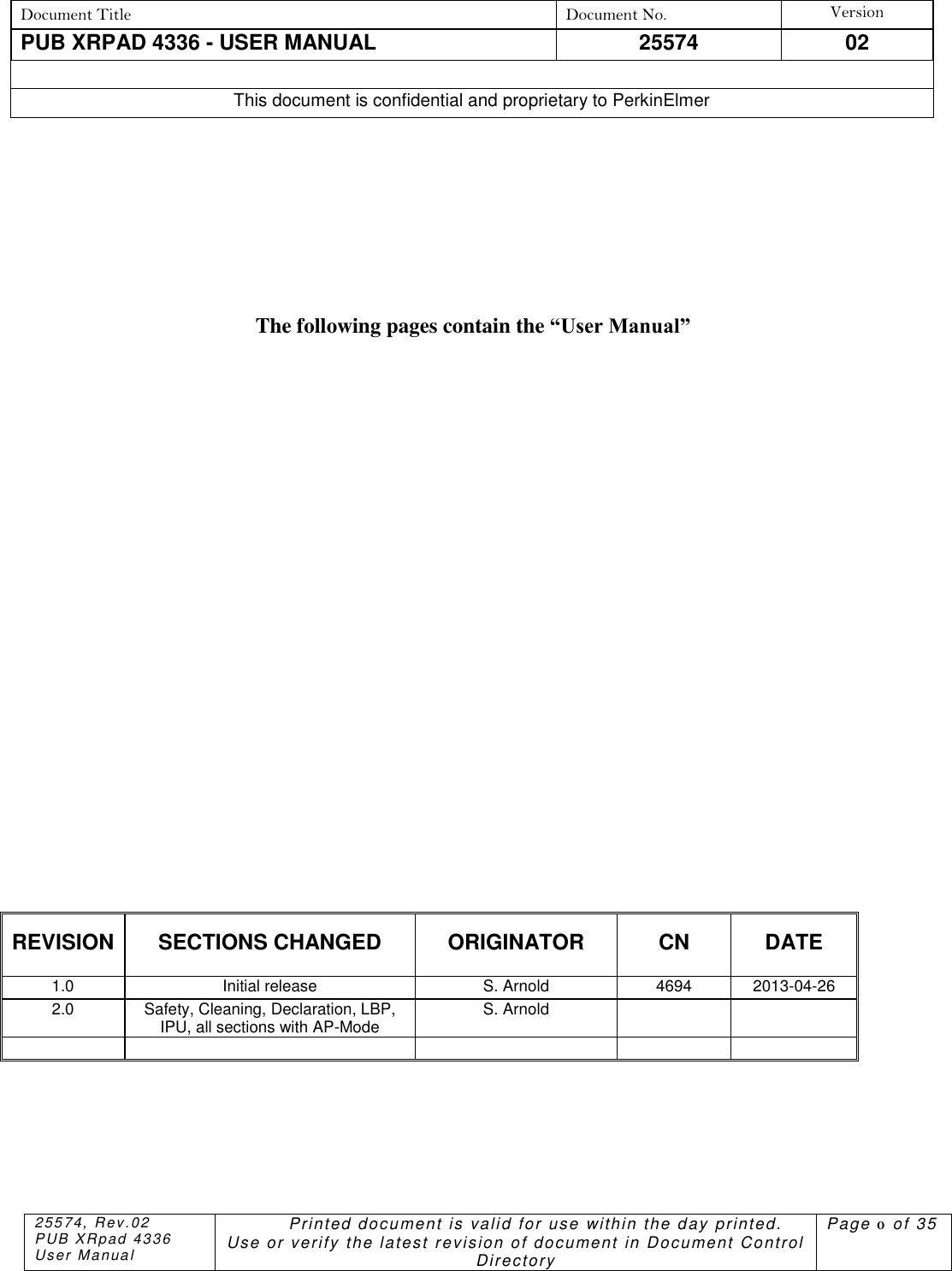
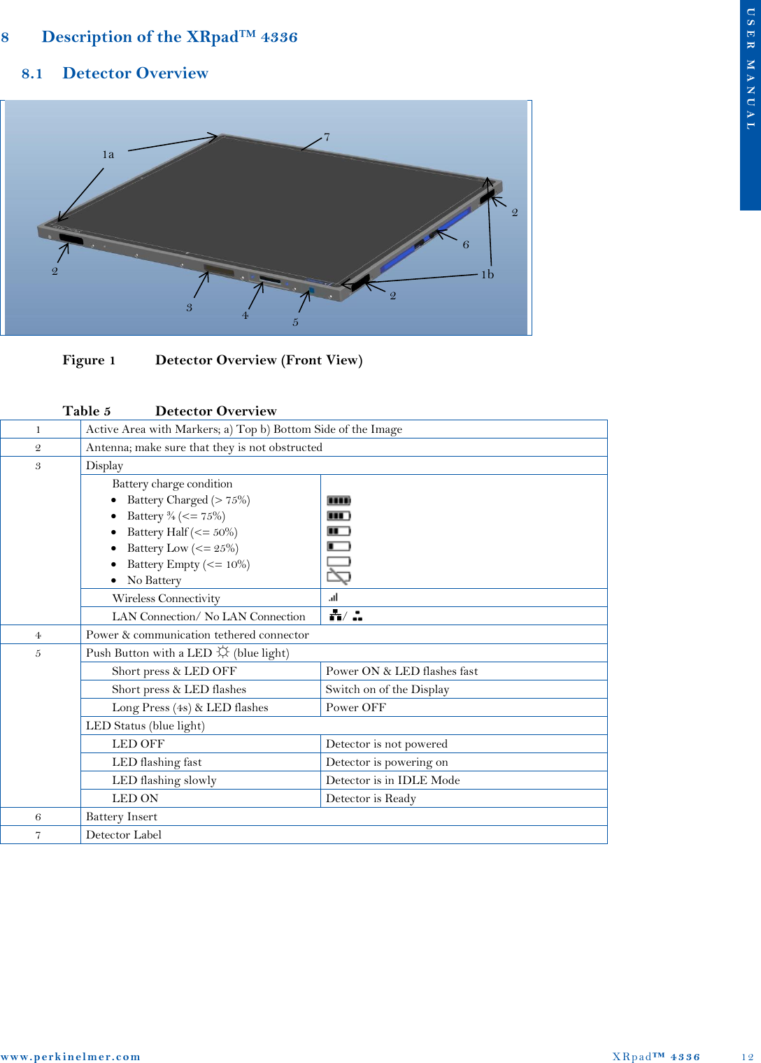
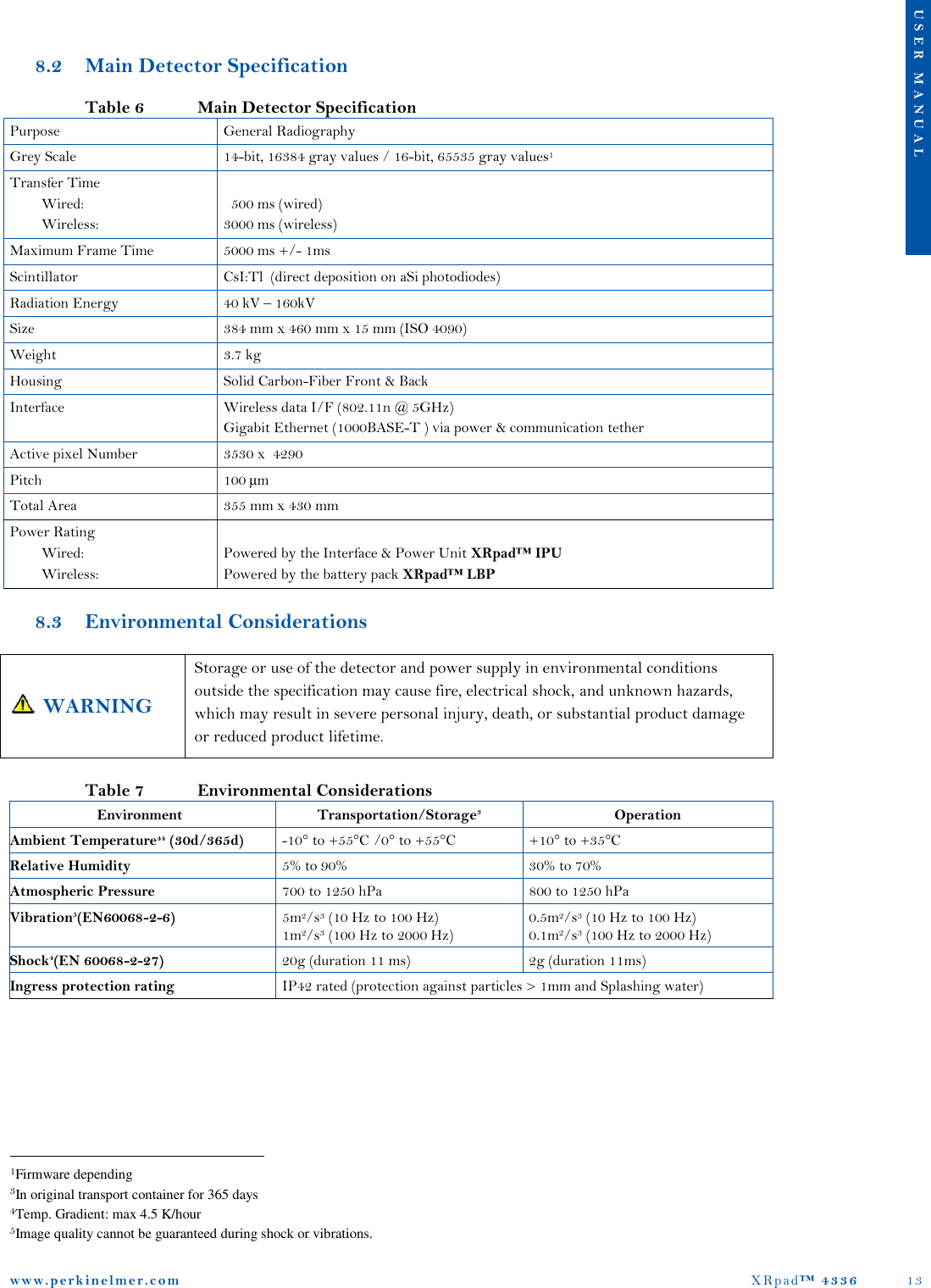
![www. p e r k i n e l m e r . c o m XRpad™ 4336 20 U S E R M A N U A L Table 11 Specification of the XRpad™ IPU Electrical specification AC Input Voltage [2] 100V .. 240V AC frequency [2] 50Hz / 60Hz DC output [7] 12.5V / 5A, 15V / 1A (voltage level is dependent of load) Trigger In Signal from Hand Switch [8] 5V .. 24V /10mA (SELV) Trigger Out Signal to Generator [9] Same level as Trigger In Signal Trigger In Signal [10] 3.3V ... 5V (SELV) Trigger Out Signal [10] 3.3V DC output 5PF [10] 5V / 100mA Trigger In Signal [10] 3.3V ... 5V (SELV) Mechanical Specification Size 311 mm x 230 mm x 60 mm Temperature ranges Operating +10° to +35°C Transportation/Storage -10° to 70°C Relative Humidity Operating 10% to 90% Transportation/Storage 0% to 90% Ingress protection rating IP40 rated (protection against particles > 1mm) WARNING All external signals which are connected to the IPU (especially PREP/EXPOSE and Trigger signals) should be from SELV (Separated or safety extra-low voltage) circuit. Ignoring this warning may result in electric shock, which may result in severe personal injury, death, or substantial product damage. 8.5.2.1 Cleaning of the XRpad IPU If the XRpad™ IPU surface is dirty or dusty, it should be cleaned with a commercial available ethanol papers or a cleaning cloth tightly wrung out of ethanol or a diluted neutral detergent. If you are using a disinfectant other than those specified, we recommend you consult a specialist for the procedure for disinfection. Turn OFF the XRpad™ IPU and disconnect the AC power cable, the detector power, and detector communication tethered cables before cleaning. WARNING When the Power and Interface Unit is going to be cleaned, be sure to turn OFF the XRpad™ IPU, and unplug all cables. Never use thinner, benzine, acetone, or other flammable cleaning agents. Ignoring this warning may result in explosion, fire, or electric shock, which may result in severe personal injury, death, or substantial product damage.](https://usermanual.wiki/Varex-Imaging-Deutschland/XRPAD.Users-Manual-XRPad-4336-pdf/User-Guide-2143535-Page-21.png)
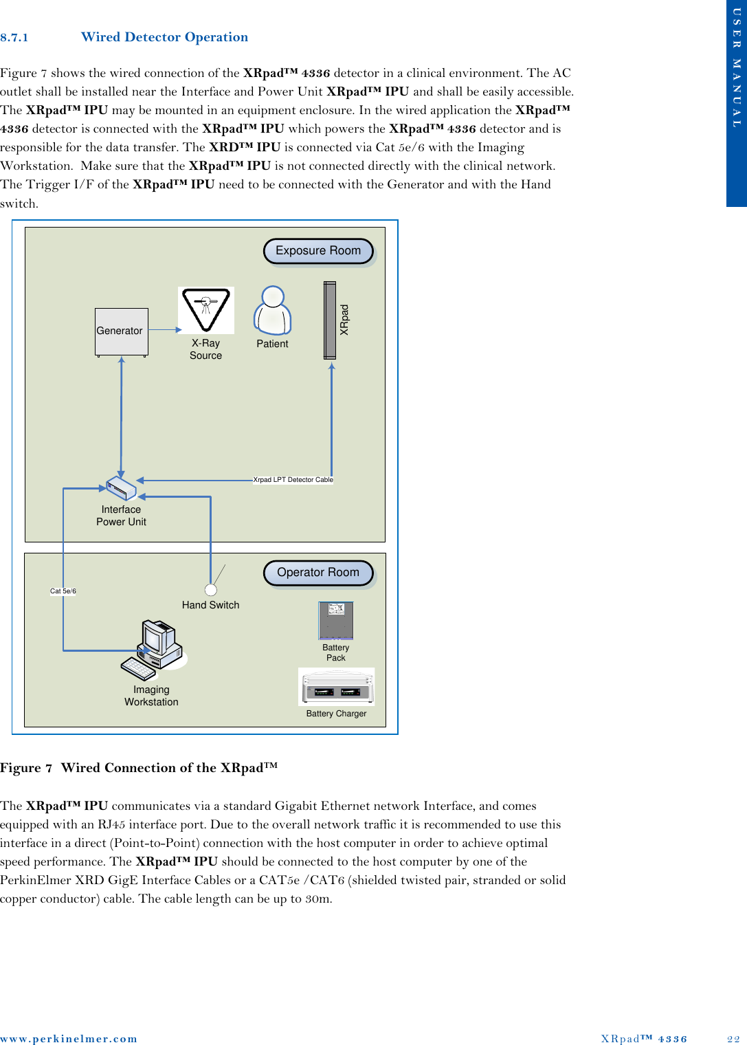
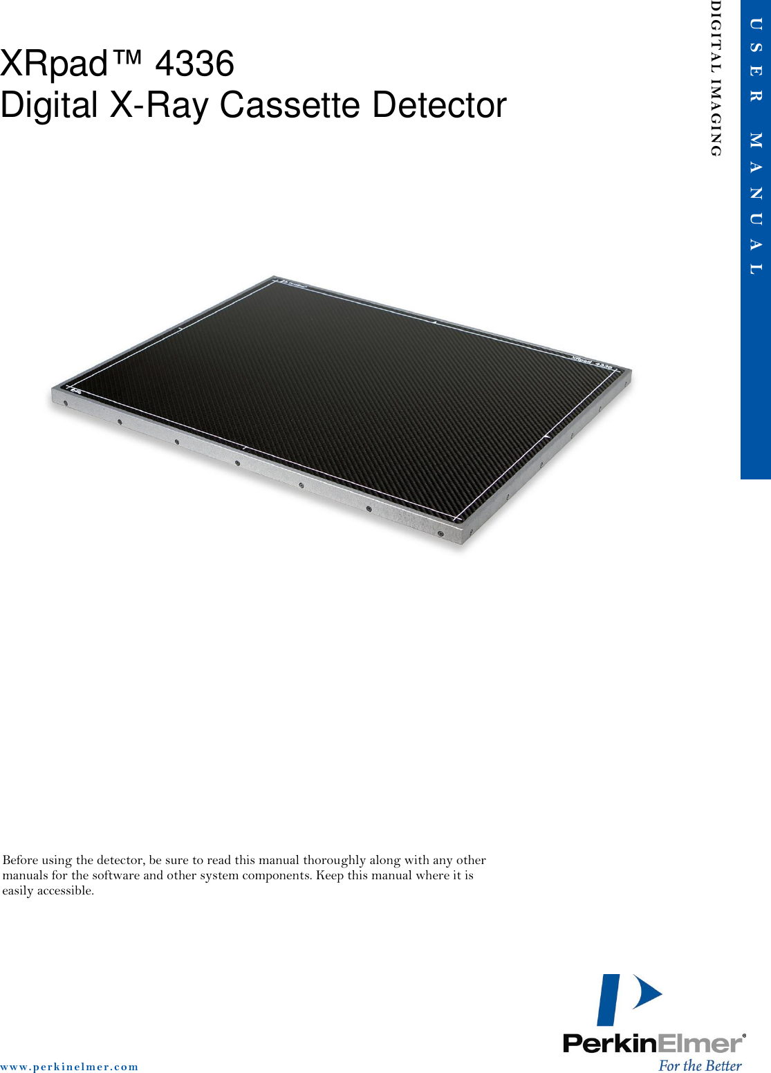
![www. p e r k i n e l m e r . c o m XRpad™ 4336 23 U S E R M A N U A L 8.7.2 Wireless Detector Operation Figure 8 shows the wireless connection of the XRpad™ 4336 detector in a clinical environment. The XRpad™ 4336 detector is connected via WLAN over a WiFi Access Pointer with the Imaging Workstation. The WiFi Access Pointer may be wall or ceiling mounted to maximize wireless signal strength. Make sure that the Router is not connected directly with the clinical network. Before imaging make sure that the XRpad™ LBP charge is sufficient and that the XRpad™ 4336 detector antenna is not obstructed. Figure 8 Wireless Connection of the XRpad™ 8.7.3 Before Using the X-ray Detector Sudden cooling or heating of the room will cause condensation. In this case, wait until condensation disappears before powering ON the XRpad™ 4336 detector. WARNING If the detector system is used under condensation conditions, problems in image quality or malfunction of the detector system may occur. In addition, this may cause fire, electrical shock, and unknown hazards, which may result in severe personal injury, death, or substantial product damage. Caution The XRpad™ 4336 should only be used with an inserted XRpad™ LPB or XRpad™ Protective Insert PatientX-Ray SourceGeneratorXRpadHand SwitchImaging WorkstationWiFi Access Point [Router]Exposure RoomOperator RoomBattery PackBattery Charger](https://usermanual.wiki/Varex-Imaging-Deutschland/XRPAD.Users-Manual-XRPad-4336-pdf/User-Guide-2143535-Page-24.png)
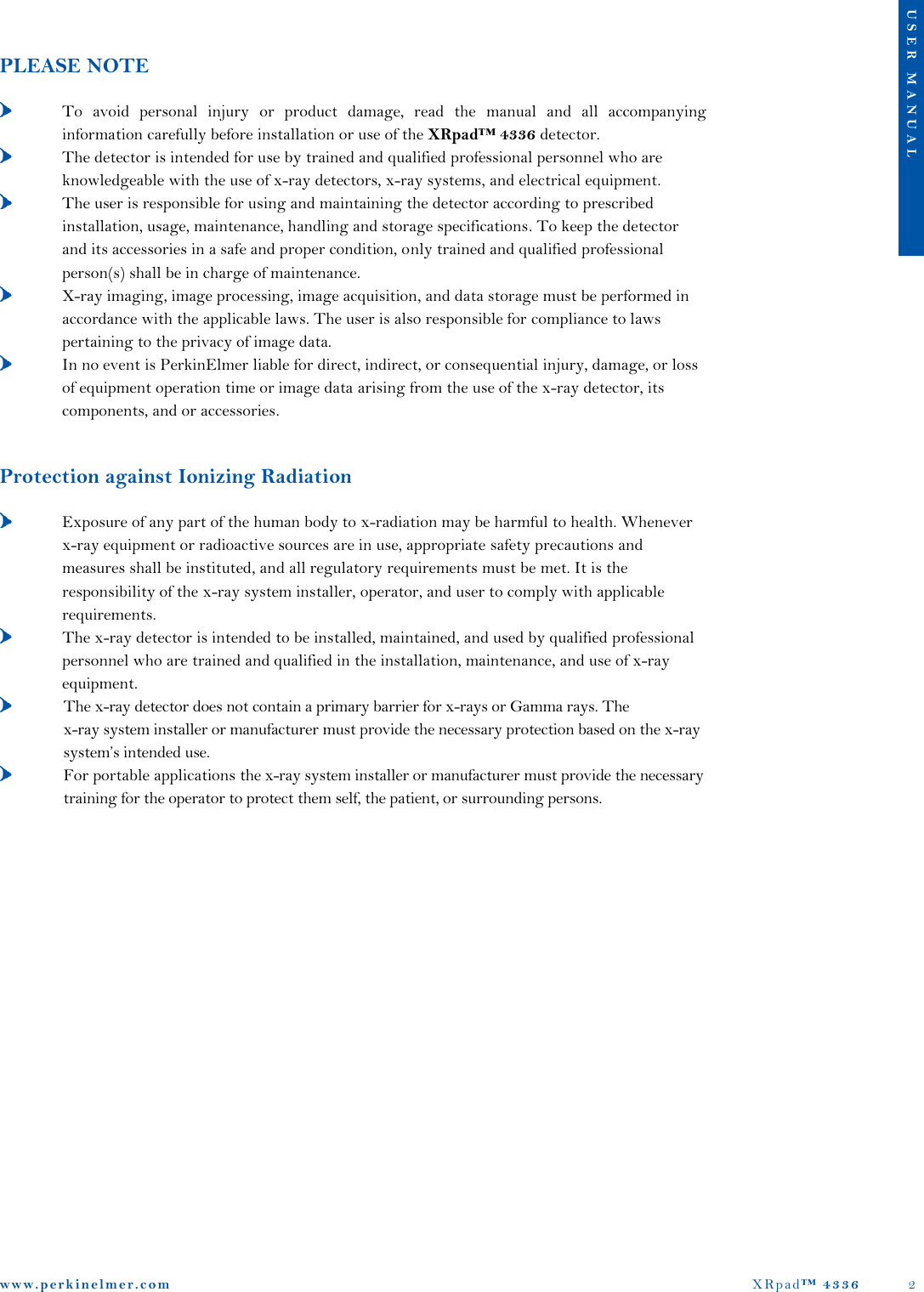
![www. p e r k i n e l m e r . c o m XRpad™ 4336 31 U S E R M A N U A L Table 14 Recommended Separation Distance between Portable and Mobile RF-Communication Equipment and the X-Ray Detector Recommended Separation Distance between Portable and Mobile RF-Communication Equipment and the X-Ray Detector The x-ray detector is intended for use in the electromagnetic environment specified below. The installer, x-ray system manufacturer, or user of the x-ray detector should assure that it is used in such an environment. Rated Maximum Output Power of the Transmitter (W) 150 kHz to 80 MHz Pd 2.1 80 MHz to 800 MHz 800 MHz to 2.5 GHz Pd 3.2 0,01 0.12 0.12 0.23 0,1 0.38 0.38 0.73 1 1.2 1.2 2.3 10 3.8 3.8 7.3 100 12 12 23 For a transmitter rated at a maximum output power not listed above, the separation distance can be estimated using the equation in the corresponding column, where P is the maximum output (power rating of the transmitter in watt [W]) according to the transmitter manufacture and d as the recommended separation distance in meter (m). Note: This guideline may not apply in all situations. Electromagnetic propagation is absorption and reflection from structures, objects, and people. Table 15 Guidance and Manufacturer’s Declaration of Electromagnetic Immunity (Portable Equipment) Guidance and Manufacturer’s Declaration of Electromagnetic Immunity The x-ray detector is intended for use in the electromagnetic environment specified below. The installer, x-ray system manufacturer, or user of the -ray detector should assure that it is used in such an environment. Immunity Test IEC 60601 Test Compliance Electromagnetic Environment – Guidance Conducted radio-frequency fields (CEF) IEC 61000-4-6 Radiated electromagnetic field (REF) IEC 61000-4-3 3 V 150 kHz to 80 MHz 3 V/m 80 MHz to 2.5 GHz [V1] 3 V 150 kHz to 80 MHz [E1] 3 V/m 80 MHz to 2.5 GHz Portable and mobile RF-communication equipment should not be closer to any part of the x-ray detector including the data cables, than the recommended separation distance calculated from the equation appropriate for the frequency of the transmitter. , 150 kHz to 80 MHz ,for 80 MHz to 800 MHPd 3.2,for 800 MHz to 2.5 GHz, where P is the maximum output of the transmitter in watt (W) according to the transmitter manufacture and d is the recommended separation distance in meter (m). Field strengths outside the shielded location from fixed RF transmitters, as determined by an electromagnetic site survey10, should be less than 3 V/m. Interference may occur in the vicinity of equipment marked with the following symbol. Note 1: These guidelines may not apply to all situations. Electromagnetic propagation is affected by absorption and reflection from structures, objects, and people. Note 2: It is essential that the actual shielding effectiveness and filter attenuation of the shielded location be verified to assure that they meet the minimum specification. 10Field strengths from fixed transmitters, such as base stations for radio (cellular/cordless) telephones and land mobile radios, armature radio, AM and FM radio broadcast, and TV broadcast, cannot be predicted theoretically with accuracy. To assess the electromagnetic environment due to fixed RF transmitters, an electromagnetic site survey should be considered. If the measured field strength in the location in which the x-ray detector is used exceeds the applicable RF compliance level above, the x-ray detector should be observed to verify normal operation. If abnormal performance is observed, additional measures may be necessary, such as re-orienting or relocating the x-ray detector. Pd 2.1Pd 2.1Pd 2.1](https://usermanual.wiki/Varex-Imaging-Deutschland/XRPAD.Users-Manual-XRPad-4336-pdf/User-Guide-2143535-Page-32.png)