Varian Medical Systems X Ray RTL8812AU PaxScan 4336Wv4 Digital Image Recepter User Manual 4336Wv4 M01R1 0 Operating Instructions
Varian Medical Systems, Inc. X-Ray Products PaxScan 4336Wv4 Digital Image Recepter 4336Wv4 M01R1 0 Operating Instructions
Contents
- 1. User Manual
- 2. User Manaul Host Device
User Manaul Host Device
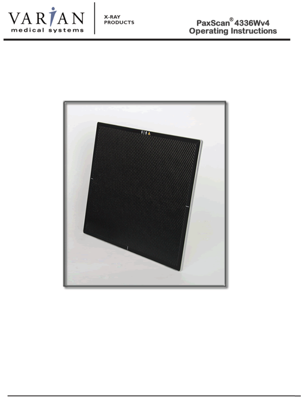
Digital Image Receptor
The PaxScan 4336Wv4 is a radiographic
digital x-ray imaging sub-system
UNRELEASED – DRAFT 090315
© Varian Medical Systems | X-Ray Products
109724-000 Rev B 09/2015

© Varian Medical Systems | X-Ray Products
1
Abstract The Operating Instructions (P/N 109724-000) covers safety, setup, operation, and maintenance
of the PaxScan 4336Wv4 radiography digital image receptor. The imager is a component sub-
system intended for integration by a qualified systems integrator.
Varian Medical System, Inc
X-Ray Products
1678 So. Pioneer Rd
Salt Lake City, UT 84104
United States
+ 1 801 972 5000 Phone
Varian Medical Systems UK Ltd.
Gatwick Road, Crawley
West Sussex RH10 9RG
United Kingdom
Notice Information in this manual is subject to change without notice. Varian is not liable for errors or
omissions contained in this manual or for any damages incurred in connection with furnishing or
use of this material.
This document contains proprietary information protected by copyright. No part of this document
may be reproduced, translated, or transmitted without the express written permission of Varian
Medical Systems, Inc.
Updates For updates to these instructions, please refer to the Release Notes.
Trademarks PaxScan® is a registered trademark and ViVA™ is a trademark of Varian Medical Systems, Inc.
Microsoft® is a registered trademark and Windows™ is a trademark
© Varian Medical Systems, Inc.
All rights reserved. Printed in the United States of America
Use is prohibited without Varian’s express written consent
Proprietary & Confidential Information

© Varian Medical Systems | X-Ray Products
2
How To Reach Us
Technical
Support
In order to provide you with the most comprehensive technical support, (hardware or
software), pleas
e complete the problem report in Chapter 10 of this manual and email to:
PAXSCAN.RMA@varian.com
before contacting your Varian representative.
To speak with our technical support personnel call:
x Call (800) 432-4422 dial 8.
For Warranty and Returns ple
ase refer to:
x https://www.varian.com/x-ray-imaging-components/service-support
© Varian Medical Systems | X-Ray Products
3
International Offices
Sales
Italy
Corso Susa, 299B
10098 Rivoli (Torino), Italy
+ 39 011 955 03 96 Phone
+ 39 011 953 62 59 Fax
Japan
6F METLIFE Kabutocho Bldg.
5-1 Nihonbashi Kabutocho
Chuo-ku Tokyo 103-0026, Japan
+ 81 3 4486 5070 Phone
+ 81 3 4486 5069 Fax
Neitherland
Zutphensestraat 160A
6971 ET Brummen
The Netherlands
+ 31 575 566 093 Phone
+ 31 575 566 538 Fax
Switzerland
P.O. Box 38
1714 Heitenried – Switzerland
+ 41 26 495 32 58 Phone
+ 41 26 495 32 59 Fax
Sales and Technical Support
China
Varian Pan-Pacific Beijing Branch
No. 8 Yun Cheng Street
Beijing Economic – Technological Dev
elopment
Area (BDA)
Beijing 100176, China
E-mail: xraychina@varian.com
+ 010 8785 8785 Phone
+ 010 8785 8954 Fax
Varian Pan-Pacific Shanghai Branch
Room 2208, Central Plaza
227 North HuangPi Road
Shanghai 200003, China
+ 86 21 6375 8953 Phone
+ 86 21 6375 8957 Fax
Sales, Technical Service and Warehouse
Germany
Karl-Arnold-StraBe 12
D-47877 Wilich, Germany
Sales, Technical Service and Warehouse
E-mail: sales-xray@varian.com
+ 49 2154-92 4980 Phone
+ 49 2154-92 4994 Fax
© Varian Medical Systems | X-Ray Products
4
General Safety Information
PLEASE READ THIS ENTIRE MANUAL BEFORE USING. PRIOR TO USING
PLEASE
ENSURE UNDERSTADING OF THE WARNING, PRECAUTIONS AND
ADVERSE EFFECTS RELATING TO THIS DEVICE.
Safety Warnings, Precautions and Contraindications
Warning:
For portable applications, the operator and end-user must take precautions
to protect themselves against dangerous X
-
ray exposure when using the
flat panel imager in the X-ray beam path of an X-ray source.
Warning:
The 4336Wv4 is not intended to be used as a primary barrier to X-rays.
The user is responsible for ensuring the safety of the operator, bystanders,
and the subjects being radiographed
Warning:
The equipment is not suitable for use in the presence of a flammable
anesthetic mixture with air, oxygen or nitrous oxide.
Warning:
Do not exceed maximum load weight of 100kg over a diameter of 40mm
and 150kg distributed around the entire surface of the panel.
This device is not intended to supply heat to a patient. However,
during normal use surfaces will become heated due to power
dissipation in the imager.
Be aware that the 4336Wv4 is an applied part (patient contact
device) and the surface shall not excee
d 41 degrees C. See
Figure
1
-0 for the view of the patient contact surfaces.
Internal temperature
sensor data is provided in the diagnostic data attached to each image.
These temperature measurements are well correlated with the panel
external surface
temperature. It is advisable to monitor this
diagnostic
data as an additional safety precaution.
Note:
There are no contraindication situations
.
© Varian Medical Systems | X-Ray Products
5
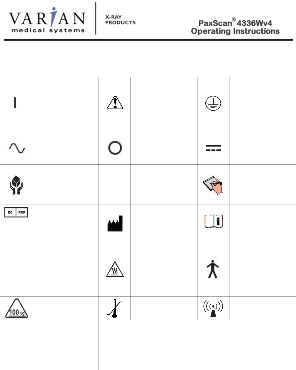
Explanation of Symbols
On (power: connection
to the mains)
Caution / Warning /
Important: Describes
action or conditions
that could result in
equipment damage,
data loss, or personal
injury
Protective Earth
Ground
Alternating Current
Off (power:
disconnection from the
mains)
Direct Current
Handle With Care
f
Indicates step-by-step
d
escription of the
respective function
follows
Useful / Important
information
Authorized
Representative in the
European
Community/European
Union
Manufacturer
Consult Instruction
for Use
IP5
1
Protected from limited
dust ingress
Protected from
con
densation -
PaxScan 4336Wv4
Receptor
Heated Surface
Type B Applied Part
Load Weight
Restriction
Temperature Limits
Non
-
ionizing radiation
IP20
Protected from touch
by objects greater than
12 millimeters, not
protected from liquids
–
Varian Battery
Charger

© Varian Medical Systems | X-Ray Products
6
Chapter Summary
1
Introduction
2
Getting Started
3
PaxScan Software
4
Modes of Operation
5
Calibration Procedures
6
Image Acquisition
7
Safety
8
Maintenance
9
Trouble Shooting
10
Problem Report
11
Appendix

© Varian Medical Systems | X-Ray Products
7
Index
How To Reach Us ............................................................................................................................................... 2
General Safety Information ................................................................................................................................. 4
Safety Warnings, Precautions and Contraindications .......................................................................................... 4
Explanation of Symbols ...................................................................................................................................... 5
Introduction ......................................................................................................................................................... 9
Shipment Contents............................................................................................................................................... 9
Optional Parts ...................................................................................................................................................... 9
Intended Use ...................................................................................................................................................... 10
Figure 1-0 Patient Contact Surfaces – 4336Wv4 ...................................................................................... 10
Getting Started ................................................................................................................................................... 11
System Overview ........................................................................................................................................... 11
Figure 2-0 Imager Configuration .............................................................................................................. 11
Figure 3-0 Imaging System Overview - without Router ......................................................................... 12
Figure 3-1 Imaging System Overview - with Router .............................................................................. 12
Figure 4-0 Imaging System Overview – Cable Connection ..................................................................... 13
Power on Sequence ........................................................................................................................................ 14
Figure 5-0 4336Wv4 Receptor Power/LED ............................................................................................. 14
Figure 5-1 4336Wv4 LED Status - Details ............................................................................................... 15
PaxScan System Software ................................................................................................................................. 17
Modes of Operation ........................................................................................................................................... 18
Table 1-0 PaxScan 4336Wv4 Operational Modes .................................................................................... 18
Default Mode ..................................................................................................................................................... 19
Operation States ............................................................................................................................................. 19
Calibration Procedures ...................................................................................................................................... 20
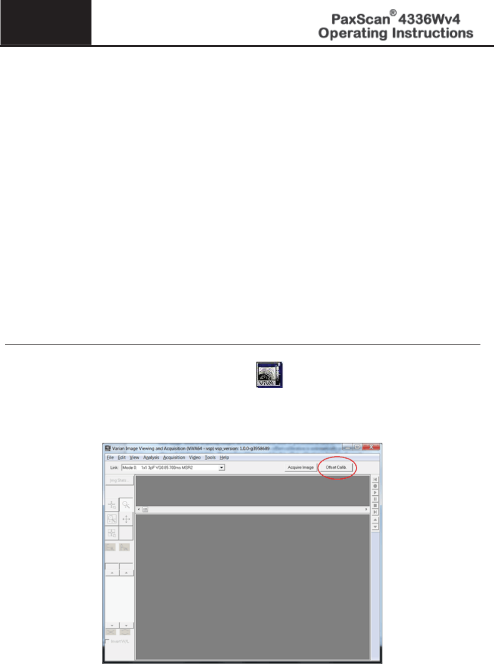
Offset Calibration .............................................................................................................................................. 20
Preview Offset Calibration ............................................................................................................................. 20
Gain Calibration ................................................................................................................................................ 22
Table 2-0 Gain Calibration: All Modes ................................................................................................... 23
Radiographic Mode Gain Calibration ............................................................................................................ 24
ViVA Mode Settings ......................................................................................................................................... 26

© Varian Medical Systems | X-Ray Products
8
Image Acquisition ............................................................................................................................................. 28
Radiography Mode ......................................................................................................................................... 28
Safety ................................................................................................................................................................. 31
Electro-Magnetic Interference ........................................................................................................................ 31
Table 3-0 Guidance and Mfgr Declaration - Electromagnetic Emissions ................................................ 31
Table 4-0 Guidance and Mfgr Declaration - Electromagnetic Immunity ................................................. 32
Table 5-0 Recommended Separation Distance Between .......................................................................... 34
Portable and Mobile RF Communications and the PaxScan 4336Wv4 .................................................... 34
Electrical Protection .......................................................................................................................................... 35
Environment Limits ........................................................................................................................................... 35
Temperature, Humidity & Atmospheric Pressure .......................................................................................... 35
Altitude Limits .................................................................................................................................................. 35
Varian Lithium-Ion Rechargeable Battery ..................................................................................................... 36
Lithium-Ion Battery Handling, Storage, & Shipping ..................................................................................... 36
Regulatory ......................................................................................................................................................... 37
Radio Frequency (RF) Compliance Information ............................................................................................... 38
FCC/IC Compliance ....................................................................................................................................... 38
Industry Canada Notice .................................................................................................................................. 39
European Community – CE Notice ................................................................................................................ 39
Maintenance ...................................................................................................................................................... 43
Cleaning and Disinfection .............................................................................................................................. 43
Repairs............................................................................................................................................................ 44
Proper Disposal ................................................................................................................................................. 44
Troubleshooting ................................................................................................................................................. 45
PaxScan 4336Wv4 Problem Report Customer Information .............................................................................. 46
Appendix A ....................................................................................................................................................... 47
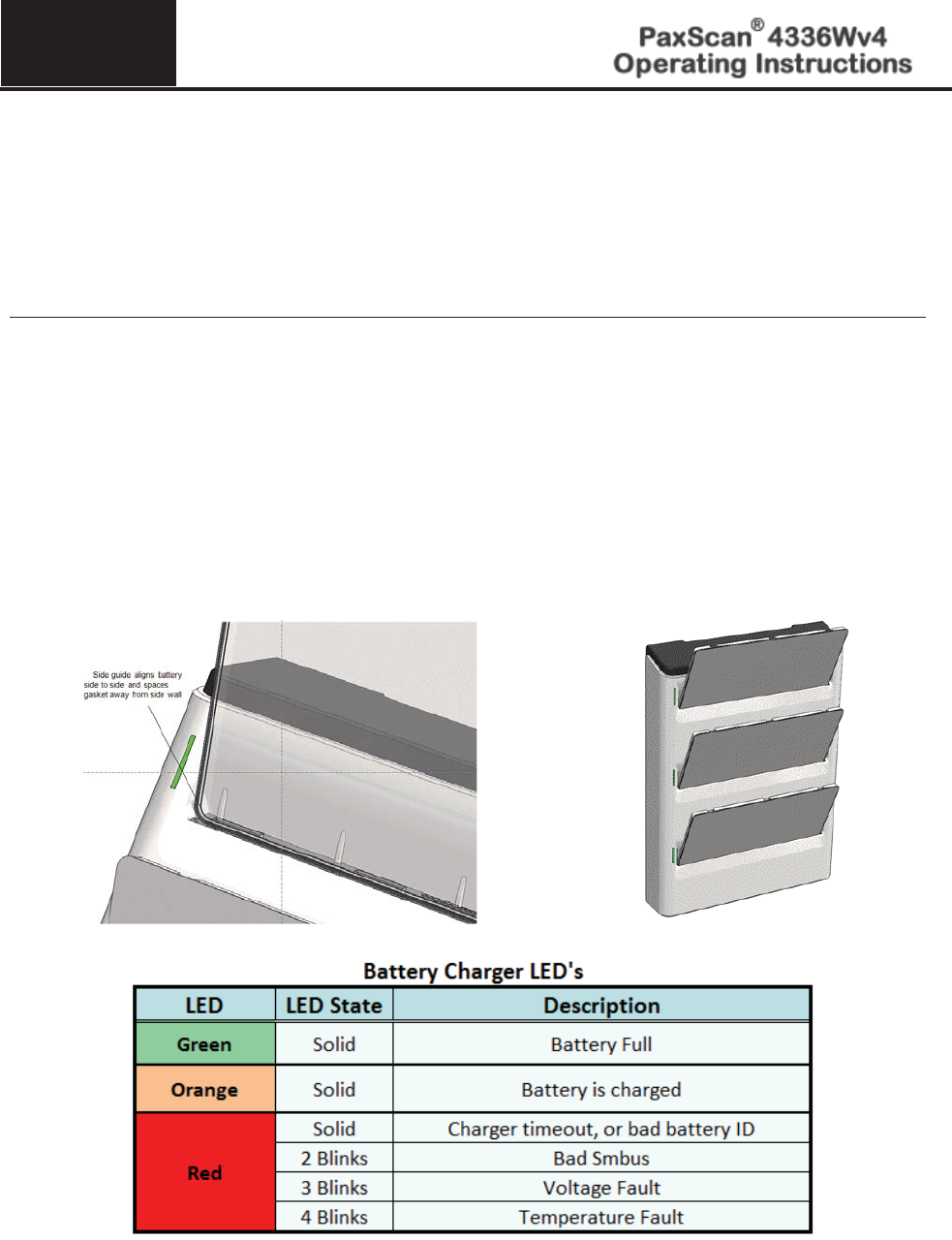
Battery Installation/Removal for 4336Wv4 ...................................................................................................... 47
Battery Charger ................................................................................................................................................. 49
Figure A-1 3-Bay Battery Charger Status Indicators .............................................................................. 50
Figure A-2 1-Bay Battery Charger Status Indicators .............................................................................. 51

Chapter 1
9 © Varian Medical Systems | X-Ray Products
Introduction
The PaxScan 4336Wv4 is a radiographic digital image receptor commonly referred to as a flat panel detector
(FPD). The detector together with image processing and command software called Varian Smart Panel (VSP) is
designed for integration into a complete X-ray system. The imaging system has two main system components:
The flat panel sensor, and VSP Software.
Shipment Contents
Flat Panel Receptor Assembly (includes a back-up cable for image recovery)
PaxScan Receptor Test Results DVD
(Files specific to the receptor in the shipment)
PaxScan Software DVD
VSP/ViVA System Software M01
PaxScan 4336Wv4 Operating Instructions
Optional Parts
Lithium-ion Battery – Varian model
– P/N 30773 (gray), 57834 (white), 81701 (black)
Battery Charger – Varian model
Laptop Style Power Supply for 1-Bay Battery Charger (includes power cable)
– P/N 82351 (black)
(OEM) Electrochem Solutions, Inc
Laptop Style Power Supply for 3-Bay Battery Charger (includes power cable)
– P/N 35205 (gray/white), 82350 (black)
(OEM) Electrochem Solutions, Inc.
Laptop Style Power Supply for 1-Bay Battery Charger (includes power cable)
– P/N 117402
Laptop Style Power Supply for 3-Bay Battery Charger (includes power cable)
– P/N 44666
Customer Specific Overlay
Immediately upon receipt, inspect the shipment and its contents against the Delivery Note enclosed with the
shipment for evidence of damage or missing components. Save all shipping containers in case a return is
warranted. If there is any discrepancy, please call the PaxScan Service Center at (800) 432-4422 or (801) 972-
5000.
1
© Varian Medical Systems | X-Ray Products
10
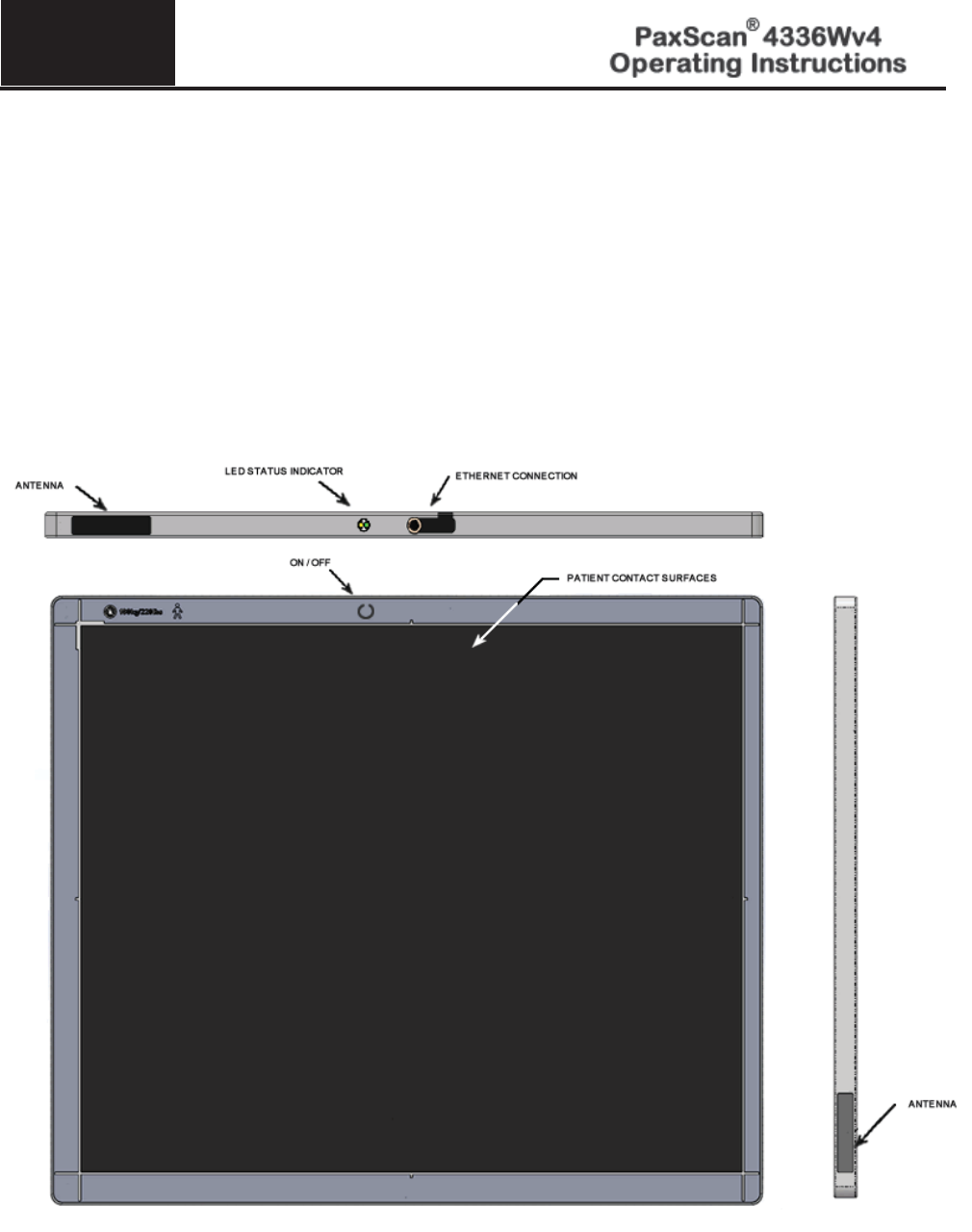
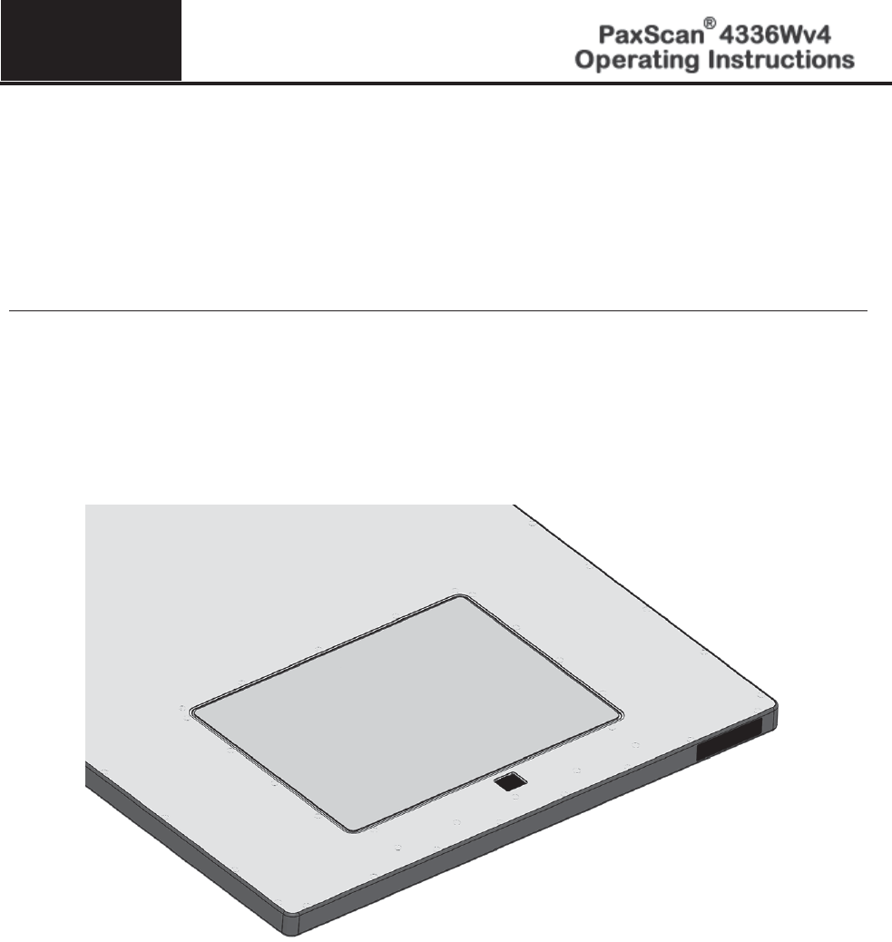
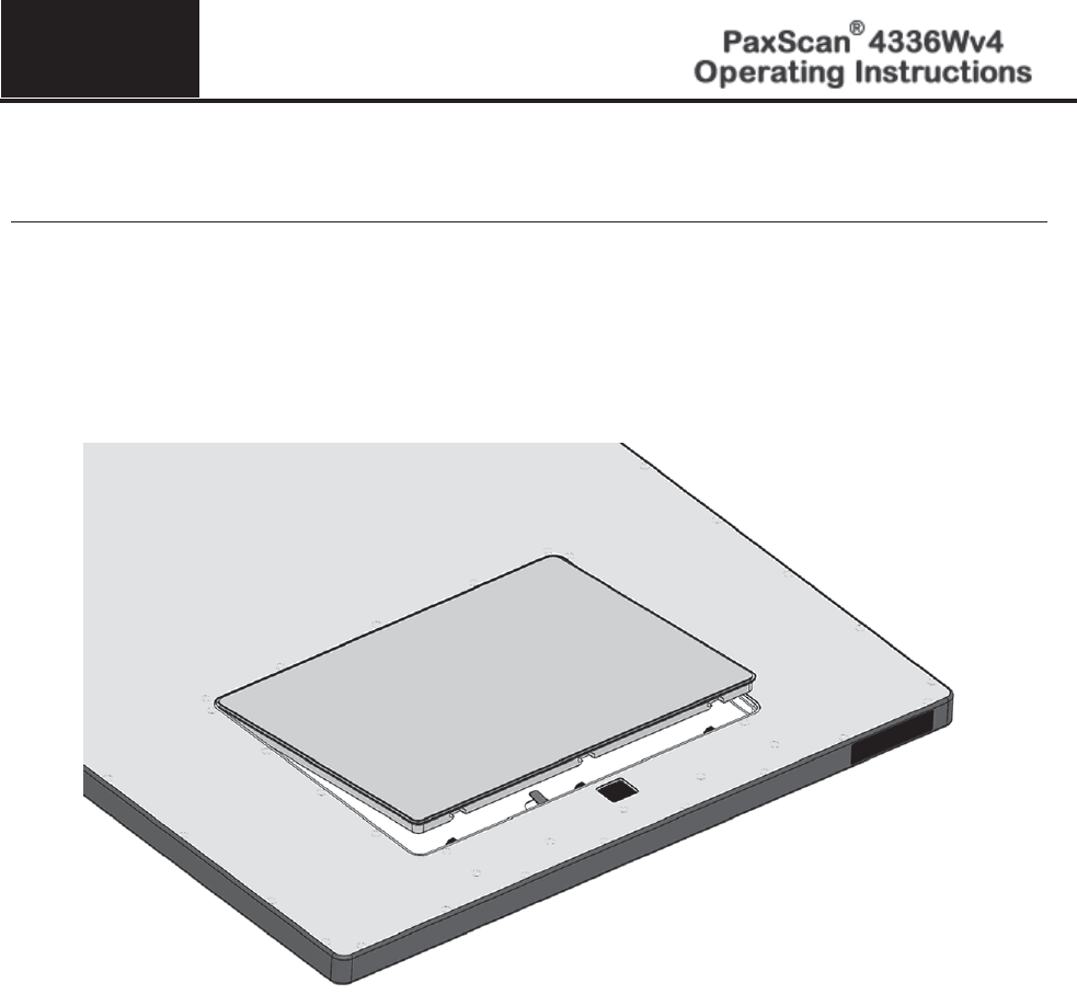
Intended Use
The PaxScan 4336Wv4 receptor is a light weight, wireless flat panel detector designed for medical and
veterinary use. The 4336Wv4 fits standard bucky trays and its wireless communication enables easy migration
between table, above the table, chest stand, and mobile cart applications. This family model will acquire image
over a wide range of dosage, while providing maximum access to the patient, with a minimum possible border
on the active imaging area. An additional cable is supplied with the receptor to allow for set-up of the wireless
interface and retrieve images from the receptor in the case of failed wireless transmission.
Figure 1-0 Patient Contact Surfaces – 4336Wv4
Chapter 2
© Varian Medical Systems | X-Ray Products
11
Getting Started
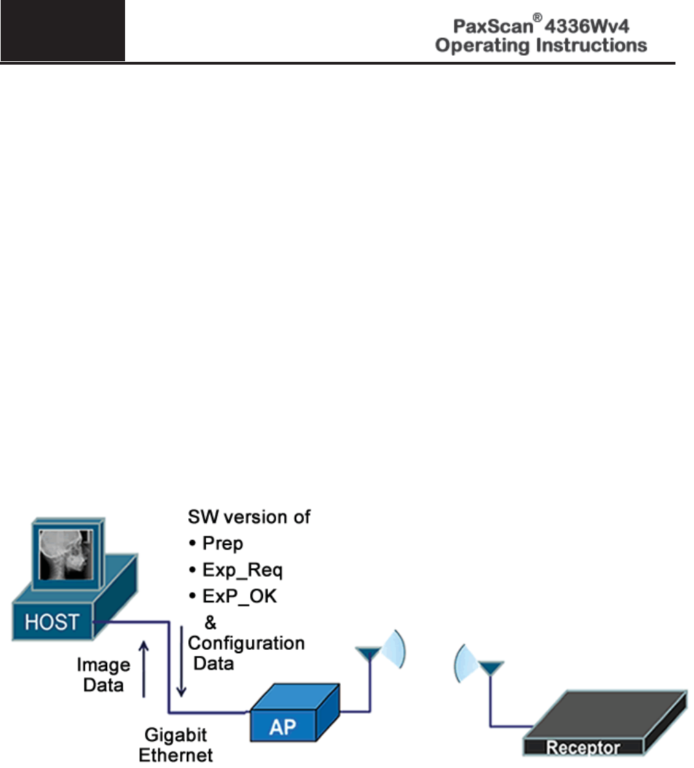
System Overview
In medical applications, the function of the 4336Wv4 FPD is to absorb the X-rays that pass through the
patient’s anatomy and convert them into a digital image. The wireless access point is the interface between
the FPD and the imaging system and may be mounted in an equipment enclosure, or it may also be wall or
ceiling mounted to maximize wireless signal strength. The Receptor is provided with a software application
package, Virtual Command Processor (VSP), which performs all the interface functions with the receptor;
such as, communication and respective calibration. During operation, the Receptor is often draped or
bagged to ensure cleanliness and sterilization, and is manipulated such that the Receptor’s input window is
located near, but on the opposite side of the patient, from the X-ray source.
Figure 2-0 shows the configuration of the Receptor in the context of the overall imaging system. The
dimensions for receptor are 459.5mm x 383.5 x 15.13mm.
Figure 2-0 Imager Configuration
2
© Varian Medical Systems | X-Ray Products
12
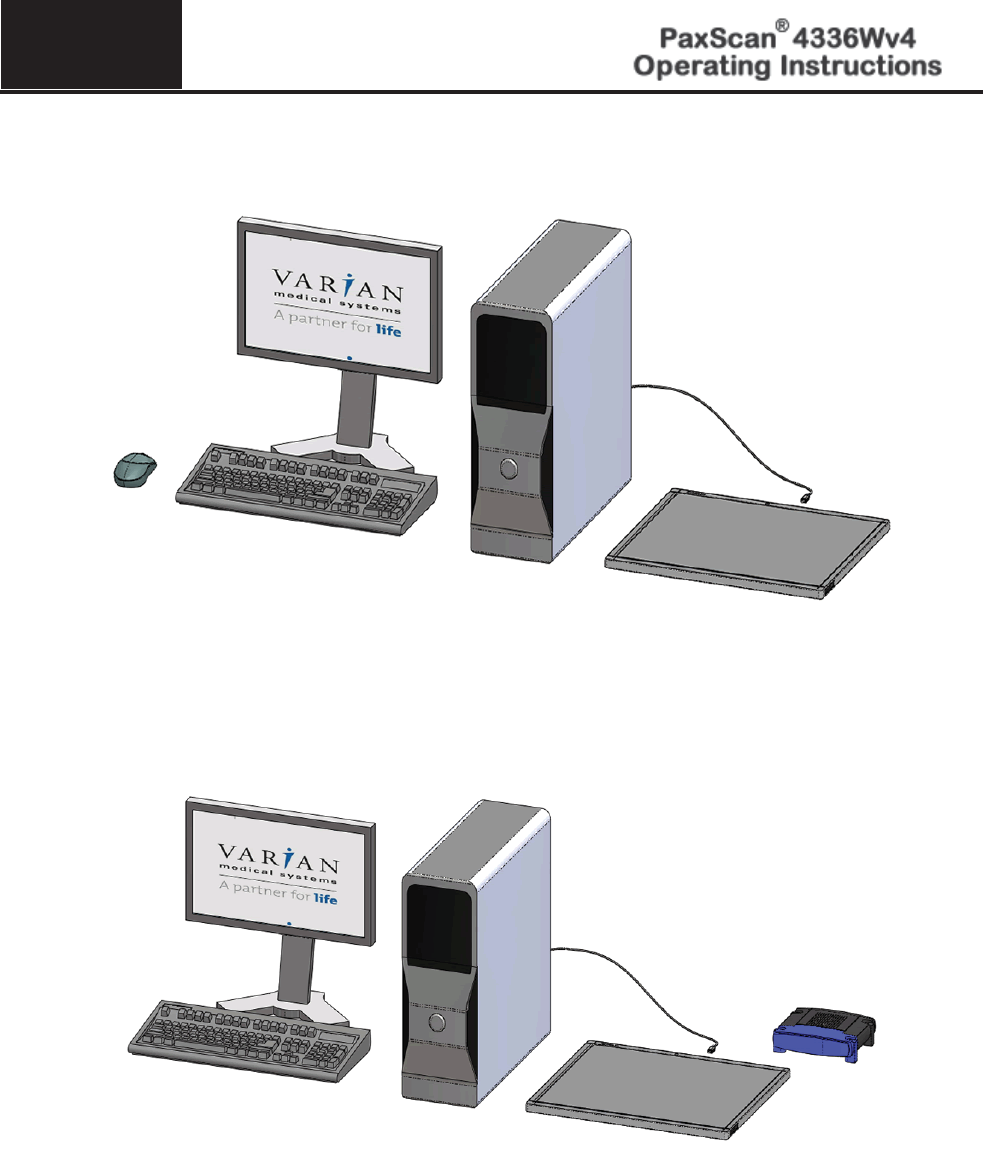
Figure 3-0 Imaging System Overview - without Router
Figure 3-1 Imaging System Overview - with Router
2
© Varian Medical Systems | X-Ray Products
13
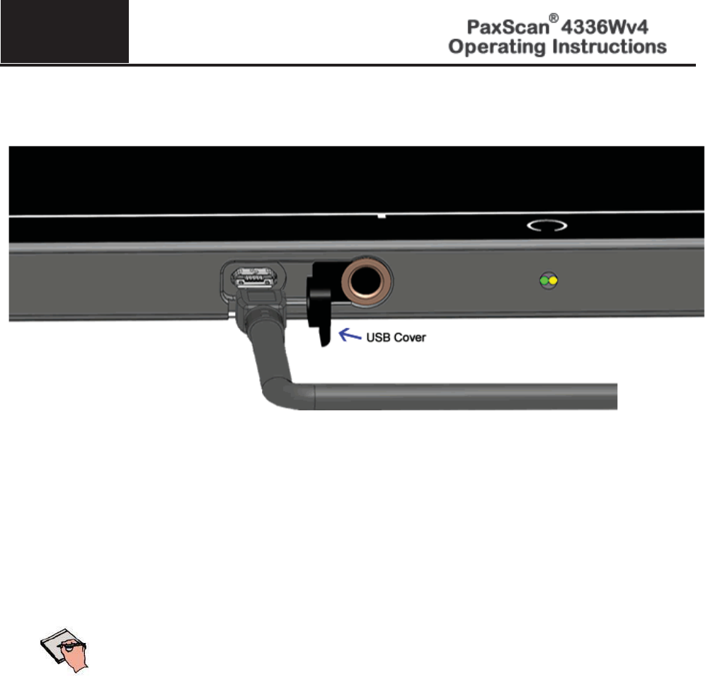
Figure 4-0 Imaging System Overview – Cable Connection
Note:
There is one (1) cable connections for the 4336Wv4 Flat Panel Receptor
which is the back
-up cable.
This cable functions as an interface between the
receptor and the workstation by providing a 100T Ethernet connection for set-
up of the wireless interface and retrieval of images in the case of wireless
transmission failure.
2
© Varian Medical Systems | X-Ray Products
14
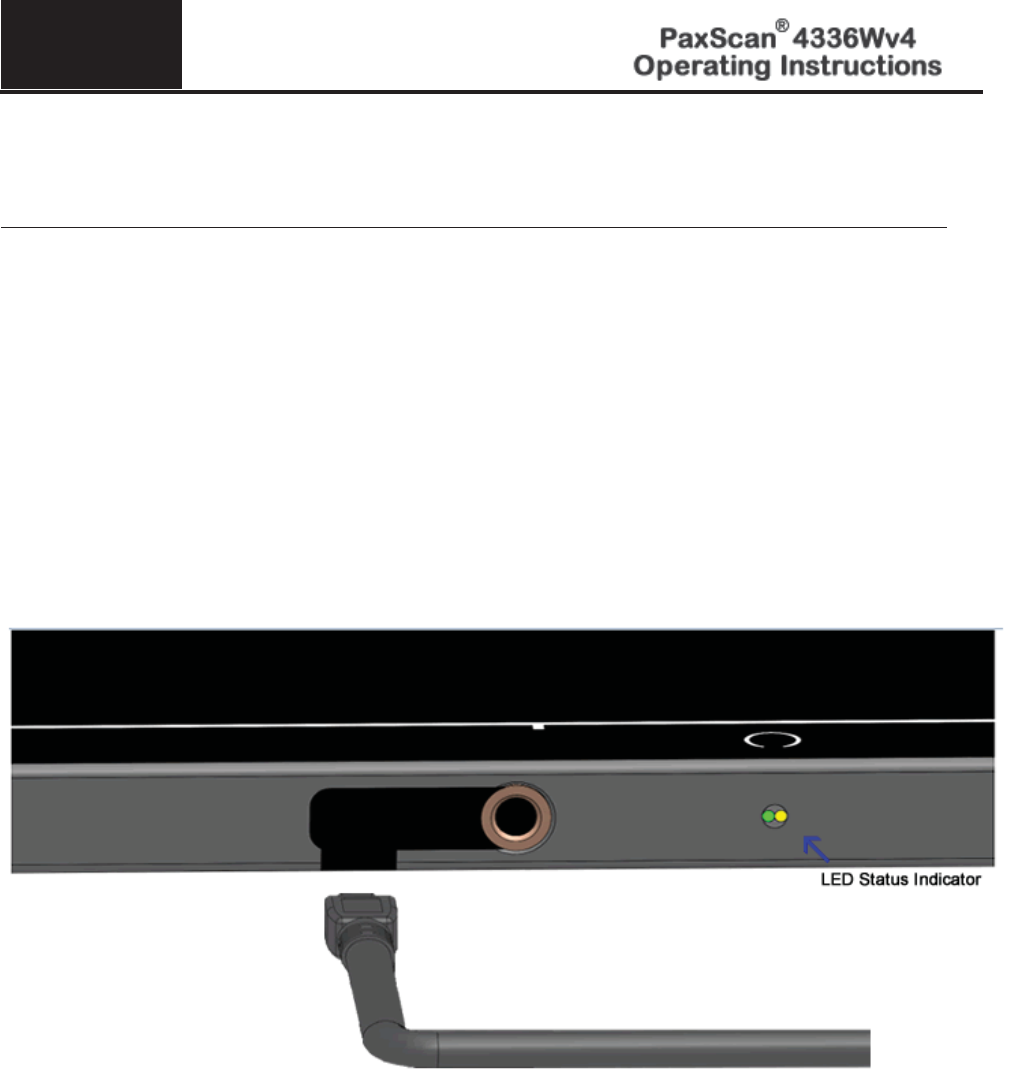
Power on Sequence
Step
Action / Results
1.
Place battery into receptor making sure the battery latches into place. The receptor will
automatically power on when battery is inserted.
2.
The yellow and green LEDs are solid while receptor boots.
3.
Wireless connected is green blinking.
4.
The yellow LED indicates the status of the receptor. Refer to Figure 5-1 for explanation of LED
status indicators.
Figure 5-0 4336Wv4 Receptor Power/LED
2
© Varian Medical Systems | X-Ray Products
15
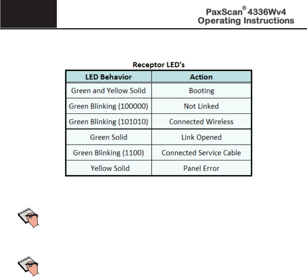
Figure 5-1 4336Wv4 LED Status - Details
Note
:
The
blinking behavior occurs based on a 4Hz clock.
Each digit for the
blinking pattern represents 1/4s
.
Important:
The
Service Cable
does not provide power to the receptor when tethered.
Before servicing, ensure that a fully charged battery is inserted.
2
© Varian Medical Systems | X-Ray Products
16
Warning:
PaxScan 4336Wv4 Moisture Resistance Level Tested, horizontal position,
x
-ray window face up, without backup cable attached; protected a
gainst
falling water equivalent to 3
-
5mm rainfall per minute for duration of 10
minutes.
Receptor
Ingress Dust Level Tested,
not entirely prevented, but must not
enter in
sufficient quantity to interfere with the satisfactory operation of
the equipment; c
omplete protection against contact (dust proof)
IP
51
Caution:
Accessory or optional equipment connected to the analog and digital
interfaces must be certified to the respective IEC standards (i.e., IEC
60950
-1 for data processing equipment and IEC 60601-
1 for medical
equipment). Furthermore, all configurations shall comply with the
system standard IEC 60601
-1-
1. Anyone connecting additional or
optional equipment to the signal inputs or signal outputs as part of a
configuration for medical equipment
is therefore responsible for
compliance with the equipment standard IEC 60601
-
1. If in doubt,
consult our technical support personnel
Warning:
Precautions should be taken to not open the receptor module.
Depending upon the type of scintillator used, opening the receptor
module may expose the user to potentially toxic materials.
Warning:
Changes or modifications not expressly approved by the
manufacturer could void the user’s authority to operate the
equipment
.

Chapter 3
© Varian Medical Systems | X-Ray Products
17
PaxScan System Software
The PaxScan 4336Wv4 receptor is part of a new series of Flat Panel Detectors which deploy the Varian Smart
Panel (VSP) architecture. Imager software is composed of two parts: 1. Software necessary to capture, process,
and correct x-ray images is embedded within the receptor; 2. The VSP COMM workstation libraries comprise the
VSP SDK. Because the main software is embedded within the receptor, the only software required on the
workstation is a small set of DLLs that should be copied from the DVD to the workstation.
The VSP COMM libraries are copied to the workstation. Software interfacing to this receptor will make API calls
to these SDK libraries to control the image acquisition process. These libraries manage connections to the
receptor and the transfer of files from the receptor to the workstation.
The contents of the DVD include the following files:
1. VSP COMM (SDK) files:
a. libvsp.dll
b. libvsp-zf.dll
c. libwinpthread.dll
d. vspcs.dll
e. vsp.h
This set of files should be copied to the workstation. For customers working with C/C++, a vsp.h header file is
included along with the libraries. For customer working with C#, the vspcs.dll provides the C# wrapper interface.
2. FP2032_VarianSmartPanel_SoftwareInterfaceSpecification.pdf – This .pdf file provides API
documentation for the software.
3. Bonjour installation files
a. Bonjour.msi
b. Bonjour64.msi
Bonjour is an optional installation and is required if you use the List()/vsp_list() API function.
4. Sample Code
a. vsp-example.cs – C# sample code project
b. vsp-example.c– C/C++sample code project
5. Utility software
a. vsp-example.exe
The vsp-file.exe utility is used to transfer a configuration file to the receptor.
Important:
F
or interfaces connection, synchronization and timing diagrams
information
please reference the Software Interface Specification.
Chapter 4
© Varian Medical Systems | X-Ray Products
18
Modes of Operation
The PaxScan 4336Wv4 supports the radiography mode of operation as defined in Table 2-0. In general, there is
a tradeoff between varying operation modes of resolution, or field of view, or cycle time, or noise. The
sensitivity of the imager is optimized to match the X-ray dose used in each mode.
The purpose of each mode is to configure the detector to achieve optimal performance during specific imaging
procedures. Modes are defined by a combination of factors, such as cycle time and analog gain. Each mode
requires a unique set of calibration files.
Note:
The system may be in only one mode at a given moment.
Not every mode will be available with every system. The OEM should
work with PaxScan technical support for configuration of the mode(s)
which best suit the customers intended application
Table 1-0 PaxScan 4336Wv4 Operational Modes
Mode
Cycle
Time
Pixel
Binning
Panel
Scan
Time
X-Ray
Window
Time
Image
Area
Frame
Size
Acquisition
Type
Radiography – Full
Resolution
7
sec
1 x 1
550ms
0.
35 to 3
.5s
Full Field
2,476 x 3,072
Accumulation

4
© Varian Medical Systems | X-Ray Products
19
Default Mode
Mode 0 is the default. The default mode will be invoked automatically upon system power-up when a link is
opened or receipt of a reset state command.
Operation States
The operational states of the imager can be categorized as follows:
x Radiography acquisition: (Radiography-type)
x Offset Calibration: (OEM-initiated)
x Gain calibration: (always-OEM initiated)
x Analog offset calibration: (always OEM-initiated)
Each operating mode employs all types of calibration. In radiography-type acquisitions, the PaxScan
4336Wv4 will acquire one frame with its respective offset.
Chapter 5
© Varian Medical Systems | X-Ray Products 20
Calibration Procedures
Offset Calibration
Offset calibration compensates for fixed pattern pixel intensity variations in the image associated with the dark
current and electronic offsets. The Offset reference image is an average of a series of frames acquired without
X-ray illumination and referred to as dark fields. f
x Offset calibration should not be performed during X-ray.
x The X-ray-to-digital conversion factor does not change as a result of calibration.
Preview Offset Calibration
There are two types of offset calibration; one is used for the preview image and the other to calibrate the
final image. Prior to acquiring images, an offset calibration must be performed in each mode. This offset
calibration is used for the preview image. In addition, an offset calibration is automatically performed
after each single acquisition.
Step
Action / Results
1.
To perform offset calibration, click the ViVA icon launches the application
2.
Ensure required receptor appears in the Mode drop down. The 4336WV4 currently supports Rad
1x1 3pf. Click Offset Calib. Button or select from the menu bar under Acquisition.
5
© Varian Medical Systems | X-Ray Products
21
Step
Action / Results
3.
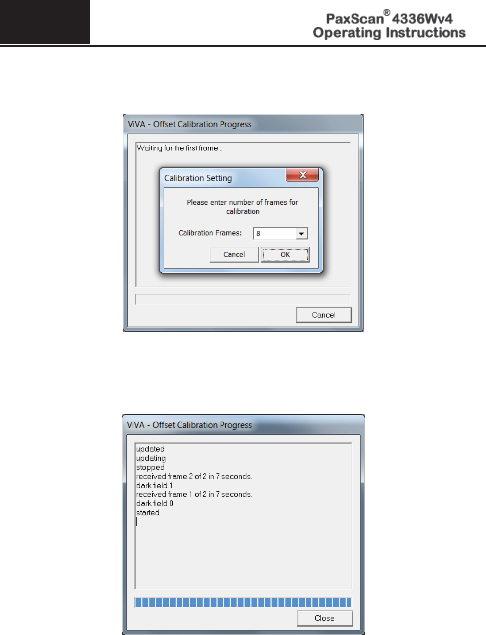
A Calibration Setting window appears followed by an offset Calibration Progress window.
4
The number of frames acquired can be selected from the Settings window. Once all frames are
acquired, the receptor is updated with the averaged offset calibration frame for the current mode.
The updated message will show on the progress window and calibration process is complete.
Press Close button to close the window.

5
© Varian Medical Systems | X-Ray Products
22
Gain Calibration
To compensate for non-uniformities in the Receptor, a gain reference image (flat field) is used by the
Corrections module as required to correct all images. The flat field image must be captured by the Varian
Smart Panel (VSP) prior to acquiring images. The process of capturing the flat field image is known as Gain
Calibration.
Note:
Every time a gain calibration process is run, an offset calibration is
enforced beforehand
. This will ensure that the receptor is properly
calibrated.
Gain calibration is based upon the linear response of the Receptor to dose. Normalization is achieved by
applying the flat field image acquired during the Gain calibration to all images corrected by the VSP.
Normalization will fail with pixels that are responding to dose in a non-linear manner. Pixels responding to
dose in a non-linear manner are usually caused by the saturation of the Receptor, or a low signal-to-noise ratio.
Note:
It is critical to acquire the flat field image within a range that is large
enough to be higher than
the background noise created by the X-ray
source and readout electronics of the Recept
or, but lower than the
saturation point of the imager.
Flat field images acquired near or exceeding the saturation point will cause normalization failures with all
images acquired until a Gain calibration with the correct dose is performed. We recommend that flat field
images be acquired with a median count of approximately 13000 - 14000. This range will ensure that Gain
calibration will meet both the upper and lower dose requirements under all modes of operation. Dose
requirements are determined by the settings of the generator X-ray source.
To reduce the effects of noise, the average of each pixel in the flat field image is calculated by accumulating a
number of frames into an internal memory buffer, then dividing the sum of each pixel by the number of frames
acquired.
Note
:
Using larger
numbers of calibration frames to capture the flat fi
eld image
will result in more accurate
calibration.
Important:
Gain calibration requires the production of X
-
rays and therefore certain
precautions must be taken by the
human operator.
The number of calibration frames used during Gain and Offset calibrations can be adjusted under the Mode
Settings pull down menu. We recommend accumulating 32 frames for gain calibration and 8 frames for offset
calibration for optimal image quality. However, the actual number of calibration frames used must be
determined solely by the system integrator depending upon their specific performance requirements.

5
© Varian Medical Systems | X-Ray Products
23
The general procedure for Gain calibration for all modes is as follows in Table 2-0 and described in the next
section. Detailed instructions on performing gain calibrations are covered in the ViVA Online help
documentation.
Table 2-0 Gain Calibration: All Modes
Step
Action
Results
1.
Warm Up
To ensure proper warm up, the PaxScan 4336Wv4
Receptor must be operational for a least
30 minutes
prior to
Gain calibration.
2.
Offset Calibration
Software performs a new Offset calibration referred to as
dark field acquisition.
Note: X
-Rays must not be used for this part of the
calibration.
3.
X-Ray Radiation
A uniform flat field with no obstructions in the path of the
X
-
Ray beam. The radiation should ideally be at a level and
technique representative of the typical radiation dose for
the Receptor during typical procedures, keeping in mind
the general consideration outlined above.
4.
Repeat
The above procedure must be repeated for each of the
stored imaging modes.
5
© Varian Medical Systems | X-Ray Products
24
Radiographic Mode Gain Calibration
Radiography Gain calibration requires an Offset calibration performed prior to collecting the Flat Field
image. Therefore an Offset Calibration process must be run prior to the gain Calibration. X-Ray
illuminated frames are then offset-corrected and accumulated in the VSP. A series of accumulated frames
equals one radiographic X-ray exposure. Exposures are averaged to obtain the Flat Field image used by the
VSP. The number of exposures acquired can be selected from the Settings window.
Important:
VivA provides a convenience of running Offset Calibration as part of the
Gain Calibration process.
However, API driven Gain Calibrations do not automatically run Offset
Calibration. OEM Applications should be sure to run Offset Calibration
prior to Gain Calibration.
Take the following steps to complete radiographic gain calibration. f
Step
Action / Results
1.
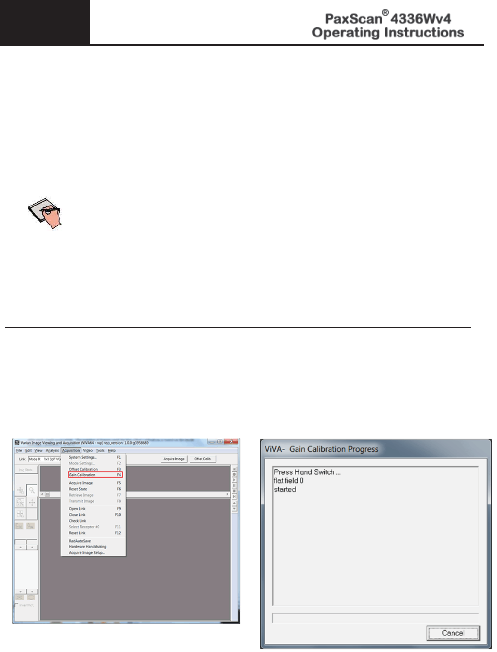
Ensure the desired receptor and imaging mode appears in the Mode drop down.
2.
Click Gain Calibration from the menu bar under Acquisition invokes hardware handshaking for the dark
field calibration.
3.
Finish Offset Calibration process as explained earlier
5
© Varian Medical Systems | X-Ray Products
25
Step
Action / Results
4.
Use operator control to perform an exposure. Once all x-ray frames have been acquired click
Finish to Complete the calibration.
The number of frames acquired can be selected from the Setting window. Once all X-ray frames
have been acquired, the receptor is updated with the averaged gain calibration from for the current
mode. The
updated message will show on the progress window and calibration process is
complete. Press Close button to close the window.
Note:
Operator Control
is user supplied equipment.
Note:
Gain calibration should be performed at regular intervals, typically once every
six
(6) months, or whenever the central beam of the X-ray source has been
moved relative to the Receptor.
Replacement of the X
-ray tube will require a new gain calibration to be
performed.
Note:
Varian recommends accumulating 32 frames for gain calibration for
optimal image quality.
However, the actual number of calibration frames
used must be determined solely by the system integrator depending upon
their specific performance requirements.
Note:
For additional assistance operatin
g
ViVA™, use the ViVA Online help
documentation.
5
© Varian Medical Systems | X-Ray Products
26
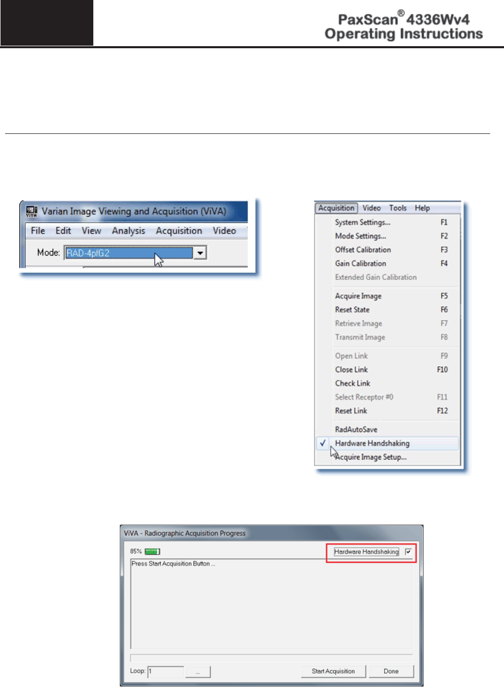
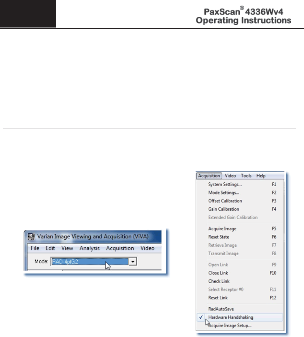
ViVA Mode Settings
The calibration and system settings are verified as follows. f
Step
Action / Results
1.
Make sure the desired receptor is selected from the Mode drop down menu; and, that “Hardware
Handshaking”
is “checked” from the menu bar under Acquisition. ViVA will remember your
preference for future launches
2.
Or check the Hardware Handshaking from Radiographic Acquisition Progress window.
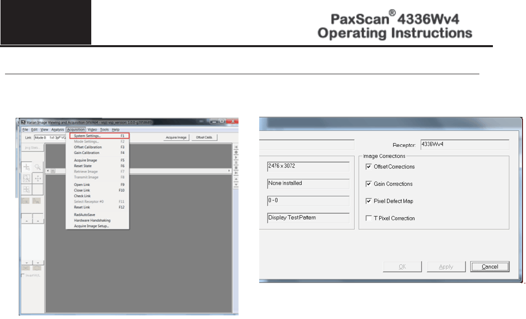
5
© Varian Medical Systems | X-Ray Products
27
Step
Action / Results
3.
System settings are verified as follows.
Chapter 6
© Varian Medical Systems | X-Ray Products 28
Image Acquisition
Once Offset and Gain Calibration is performed, you are ready to acquire images.
Radiography Mode
The Radiography mode provides the technician with superior single-shot, higher resolution images, for
diagnosis. f
Step
Action / Results
1.
Select required receptor from Mode drop down menu
2.
Make sure hardware handshaking is checked.
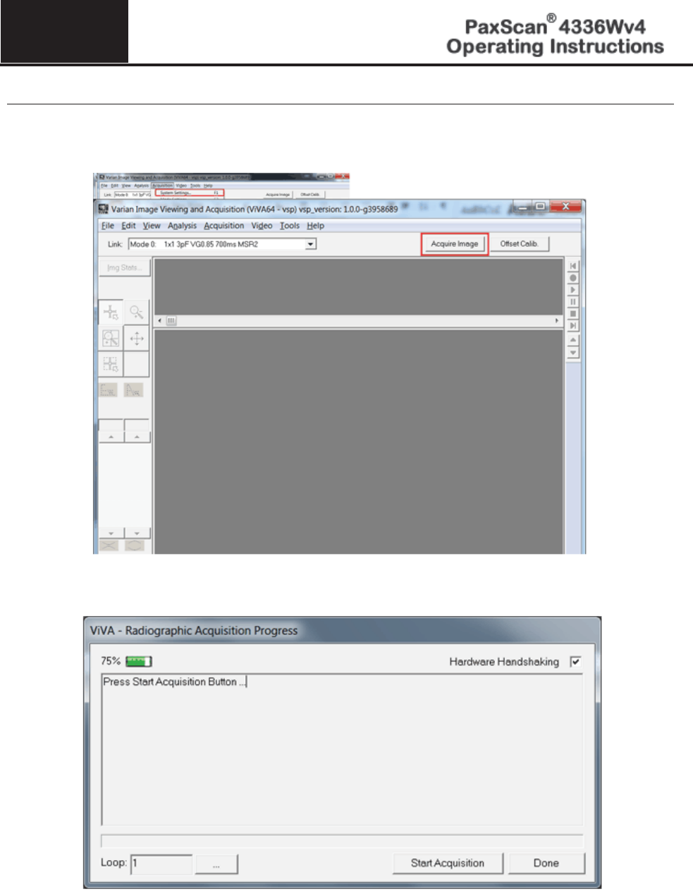
6
© Varian Medical Systems | X-Ray Products
29
Step
Action / Results
3.
Select the Acquire Image button to begin acquiring images. Acquisition Progress window will
appear. Click Start Acquisition button.
4.
Press Start Acquisition button
6
© Varian Medical Systems | X-Ray Products
30
Step
Action / Results
5.
Acquired image can be saved in the desired file format by selecting File / Save As.

Chapter 7
31 © Varian Medical Systems | X-Ray Products
Safety
Electro-Magnetic Interference
This equipment generates, uses and can radiate radio frequency (RF) energy and, if not installed and used
in accordance with the instructions, may cause harmful interference to other devices in the vicinity. In all
circumstances; however, there is no guarantee that interference will not occur in a particular installation. If
this equipment does cause harmful interference to other devices, which can be determined by turning the
equipment off and on, the user is encouraged to try to correct the interference by one or more of the
measures listed in the Troubleshooting section.
This equipment uses wireless LAN (WLAN) radios for transferring images. The WLAN power levels and
antenna configurations have been tested and certified compliant through specific absorption rate (SAR) limit set
by FCC/IC Canada (Less than 1.6W/kG) testing with separations as small as 0 cm between the panel antennas and
human tissue. While compliant, it is still recommended to reduce exposure when possible by 1) positioning
subject to be X-rayed away from the antennas (this also helps reduce image transfer time) and 2) removing the
detector panel promptly when X-ray exposure is complete. The I/O Box shall not be used at a distance of no less
than 20cm to human tissue.
Table 3-0 Guidance and Mfgr Declaration - Electromagnetic Emissions
The PaxScan 4336Wv4 is intended for use in the electromagnetic environment specified
below. The customer or the user of the
PaxScan 4336W should
assure that it is used in
such an environment.
Emissions test
Compliance
Electromagnetic environment - guidance
RF emissions
CISPR 11
Group 1
The PaxScan 4336W v4 uses RF energy only for its internal
function. Therefore, its RF emissions are very low and are
not likely to cause any interference in nearby electronic
equipment.
RF emissions
CISPR 11
Class A
The PaxScan 4336Wv4 is suitable for use in all
establishments other than domestic and those directly
connected to the public low
-voltage power supp
ly network
that supplies buildings used for domestic purposes.
Harmonic emissions
IEC 61000-3-2
Class A
Voltage fluctuations/
Flicker emissions
IEC 61000-3-3
Complies

7
© Varian Medical Systems | X-Ray Products
32
Table 4-0 Guidance and Mfgr Declaration - Electromagnetic Immunity
The PaxScan 4336Wv4 is intended for use in the electromagnetic environment specified
below. The customer or the user of the
PaxScan 4336Wv4
should assure that it is used
in such an environment.
Immunity test
IEC 60601
test level
Compliance
level
Electromagnetic environment -
guidance
Electrostatic
discharge (ESD)
IEC 61000
-4-2
+ 6 kV contact
+
8 kV air
+ 6 kV contact
+
8 kV air
Floors should be wood, concrete or ceramic
tile. If floors are covered with synthetic
material, the relative humidity should be at
least 30 %.
Electrical fast
transient/burst
IEC 61000
-4-4
+2 kV for power supply
lines
+1 kV for input/output
lines
+2 kV for power
supply lines
NA
– Only I/O is
patient cable
Mains power quality should be that of a
typical commercial or hospital environment.
Surge
IEC 61000
-4-5
+1 kV differential mode
+2 kV common mode
+1 kV differential
mode
+2 kV common mode
Mains power quality should be that of a
typical commercial or hospital environment.
Voltage dips, short
interruptions and
voltage variations
on power supply
input lines.
IEC 61000
-4-11
<5 % U
T
(>95 % dip in U
T)
for 0.5 cycle
40 % U
T
(60 % dip in U
T)
for 5 cycles
70 % U
T
(30 % dip in U
T)
for 25 cycles
<5 % U
T
(>95 % dip in U
T)
for 5 sec
<5 % U
T
(>95 % dip in U
T)
for 0.5 cycle
40 % U
T
(60 % dip in
UT)
for 5 cycles
70 % U
T
(30 % dip in U
T)
for 25 cycles
<5 % U
T
(>95 % dip in U
T)
for 5 sec
Mains power quality should be that of a
typical commercial or hospital environment.
If the user of the
PaxScan 4336Wv4
requires continued operation during power
mains interruptions, it is recommended that
the
PaxScan 4336Wv4
be powered from an
uninterruptible power supply or battery.
Power frequency
(50/60 Hz)
magnetic field
IEC 61000-4-8
3 A/m
3 A/m
Power frequency magnetic fields should be
at levels characteristic of a typical location
in a typical commercial or hospital
environment.
NOTE UT is the a.c. mains voltage prior to application of the test level.
7
© Varian Medical Systems | X-Ray Products
33
Table 4-0 continued
Immunity test
IEC 60601
test level
Complian
ce level
Electromagnetic environment - guidance
Conducted RF
IEC 61000
-4-6
Radiated RF
IEC 61000
-4-3
3 Vrms
150 kHz to 80 MHz
3 V/m
80 MHz to 2.5 GHz
3 Vrms
3 V/m
Portable and mobile RF communications equipment should
be used no closer to any part of the
PaxScan 4336Wv4
,
including cables, than the recommended separation distance
calculated from the equation applicable to the frequency of
the transmitter.
Recommended separation distance
Pd 2.1
Pd 2.1
80 MHz to 800 MHz
Pd 3.2
800 MHz to 2.5 GHz
where P is the maximum output power rating of the
transmitter in watts (W) according to the transmitter
manufacturer and
d
is the recommended separation distance
in meters (m).
b
Field strengths from fixed RF transmitters, as determined
by an electromagnetic site survey,
a
should be less than the
compliance level in each frequency range.
b
Interference may occur in the vicinity of equipment marked
with the following symbol:
Note 1 At 80 MHz and 800 MHz, the higher frequency range applies.
Note 2 These guidelines may not apply in all situations. Electromagnetic propagation is affected by absorption and reflection
from structures, objects and people.
a
Field strengths from fixed transmitters, such as base stations for radio (cellular/cordless) telephones and land mobile
radios, amateur radio, AM and FM radio broadcast and TV broadcast and TV broadcast cannot be predicted theoretically
with accuracy. To assess the electromagnetic environment due to fixed RF transmitters, an electromagnetic site survey
should be considered. If the measured field strength in the location in
which the PaxScan 4336Wv4 used exceeds the
applicable RF compliance level above, the
PaxScan 4336Wv4 should be observed to verify norma
l operation. If abnormal
operation is observed, additional measures may be necessary, such as reorienting or relocating the PaxScan 4336Wv4
b
Over the frequency range 150 kHz to 80 MHz, field strengths should be less than [V1] V/m.
7
© Varian Medical Systems | X-Ray Products
34
Table 5-0 Recommended Separation Distance Between
Portable and Mobile RF Communications and the PaxScan 4336Wv4
The PaxScan 4336Wv4 is intended for use in an electromagnetic environment in
which radiated RF disturbances are controlled. The customer or the user of the
PaxScan 4336W
v4
can help prevent electromagnetic interference by maintaining a
minimum distance between portable and mobile RF communications equipment
(transmitters) and the PaxScan 4336W
v4
as recommended below, according to the
maximum output power of the communications equipment.
Rated maximum
output power
of transmitter
W
Separation distance according to frequency of
transmitter
m
150 kHz to 80 MHz
Pd 2.1
80 MHz to 800
MHz
Pd 2.1
800 MHz to 2.5
GHz
Pd 3.2
0.01
0.12
0.12
0.23
0.1
0.38
0.38
0.73
1
1.2
1.2
2.3
10
3.8
3.8
7.3
100
12
12
23
For transmitters rated at a maximum output power not listed above, the recommended separation distance d in
meters (m) can be estimated using the equation applic
able to the frequency of the transmitter, where P is the
maximum output rating of the transmitter in watts (W) according to the transmitter manufacturer.
NOTE 1
At 80 MHz and 800 MHz, the separation distance for the higher frequency range applies.
NOTE 2
These guidelines may not apply in all situations. Electromagnetic propogation is affected by
absorption and reflection from structures, objects and people.

7
© Varian Medical Systems | X-Ray Products
35
Electrical Protection
●
The 4336Wv4 model is internally powered
Environment Limits
Rigorous environmental testing is conducted on an engineering basis using a sample receptor.
Temperature, Humidity & Atmospheric Pressure
Category
Limits
Storage & Transport (ambie
nt)
Receptor: -20º C to +70º C
Battery:
-20º C to +60º C
Battery Charger: -20º C to +60º
Storage
Humidity Range (non-condensing)
Receptor: 10% to 90%
Battery Charger:10% to 90% at 20º C
Normal Operation Temperature (measured at the center
of the back cover)
Receptor: 10º C to 35º C
Operation Humidity (non-condensing)
10% to 90%
Atmospheric Pressure Range
700hPa to 1060hPa
Normal Operation Range (ambient)
Note:
that normal charging must be terminated if
the battery cell temperature is above 45C or
below -20C. Outside of the 0º C to 35C ambient
temperature, the charger will remain active, but
the charge current will be off or limited so that
charge time will be extended.
Battery Charger:
0º C to 35C
Altitude Limits
The Paxscan Digital Imager Receptor is rated to operate at an altitude ≤ 3000m.
The Varian Battery Charger is rated to operate at an altitude -610m to 3050m (-2000 to 10,000 ft)
7
© Varian Medical Systems | X-Ray Products
36
Varian Lithium-Ion Rechargeable Battery
Please only use the lithium-ion rechargeable battery listed below that is supplied with the receptor.
Battery type: Lithium-ion
Battery model: Varian – P/N 30773 (gray), 57834 (white), 81701 (black)
Rated voltage: 14.8V 2.1Ah, 31.1 Wh
Caution:
Risk of fire, explosion or burns. Do not short circuit, crush, heat above
100ºC, incinerate, or disassemble the battery. Charge only with the
receptor or battery charger supplied
. Please follow local governing
ordinances and recycling plans regarding proper disposal or recycling of
the lithium-ion rechargeable battery.
Note:
Lithium
-ion rechargeable battery is for use with the model PaxScan
4336W
v4.
Lithium-Ion Battery Handling, Storage, & Shipping
Handling
● Do not short circuit, crush, heat above 100ºC, incinerate, or disassemble the battery.
● Do not dispose of battery in fire or water.
● Do not expose battery to temperatures above 60 °C (140 °F).
● Do not use a damage battery.
Storage
● Remove battery and store it separately from device.
● Charge or discharge the battery to approximately 50% of capacity before storage.
● Charge the battery to approximately 50% of capacity at least once every six month.
● Store the battery at temperatures between -20 °C and 60 °C (-4 °F and 140 °F).
Shipping
● Always check all applicable local, national, and international regulations before transporting
a Lithium-Ion battery.
● It is customers responsibility to ship battery according to local and international shipping regulation for
Lithium-Ion battery in effect at the time of shipment.
7
© Varian Medical Systems | X-Ray Products
37
Regulatory
●
The PaxScan® 4336Wv4 model family is a component sub-system with Type B per
Standard
for Medical Electrical Equipment. The PaxScan® 4336Wv4 model family
and
the Varian Battery Charger are
an associated equipment x-ray medical equipment with
respect to electrical shock, fire and mechanical hazards only in accordance with:
UL 60601-1 Medical Electrical Equipment, Part 1: General Requirements for
Safety 1st ed.
IEC 60601-1 Medical Electrical Equipment Part 1: General Requirements for
Safety 2nd ed.
IEC 60601-1 Medical Electrical Equipment Part 1: General Requirements for
Basic Safety and Essential Performance 3rd ed.
ANSI/AAMI ES60601-1 (2005) Medical Electrical Equipment – Part 1: General
Requirements for Basic Safety and Essential Performance.
CSA-C22.2 No 60601-1 (2008) Medical Electrical Equipment, Part 1 General
Requirements for Basic Safety and Essential Performance.
CAN/CSA-C22.2 No 601.1-M90, 2005 Medical Electrical Equipment, Part 1
General Requirements for Safety.
EN/IEC 60601-1-2 Medical Electrical Equipment Part 1-2: General Requirements
for Basic Safety and Essential Performance Collateral Standard: Electromagnetic
Compatibility 3rd ed.
RF compliant in accordance with FCC Part 15 Subpart C and Part 15 Subpart E.
●
Type B Applied Part
●
CE Mark - Varian Medical Systems’ imaging products are designed and manufactured to
meet the Low
Voltage Directive 2006/95/EC, MDD 93/42/EEC, and R&TTE Directive
1999/5/EC
●
MDD Class IIa
●
A Declaration of Conformity has been filed for this product and available upon request by
contacting Varian Medical Systems.
●
The Varian Battery Charger is a Class 1, continuous operation device and meets the
following:
IEC 61000-4-2 Electro-Static
Discharge
IEC 61000-4-3 RF
Electromagnetic Fields Immunity
IEC 61000-4-4 EFT/Burst
IEC 61000-4-5 Surge Immunity
IEC 61000-4-6 Conducted RF
Disturbances Immunity
IEC 61000-4-8 Magnetic Field
Immunity
IEC 61000
-4-11 Dips, Interruptions,
and Variations
IEC 61000
-3-2 Harmonics Current
Emission
IEC 61000
-3-3 Voltage Fluctuation
and Flicker

7
© Varian Medical Systems | X-Ray Products
38
Radio Frequency (RF) Compliance Information
FCC/IC Compliance
This device complies with Part 15 of the FCC Rules and RSS-Gen (RSS-210, etc.) of IC Rules. Operation
is subject to the following two conditions:
1. This device may not cause harmful interference.
2. This device must accept any interference received, including interference that may cause
undesired operation.
Note: This equipment has been tested and found to comply with the limits for a Class A
digital device, pursuant to part 15 of the FCC Rules and Canadian ICES-003. These limits
are designed to provide reasonable protection against harmful interference when the
equipment is operated in a commercial environment. This equipment generates, uses, and
can radiate radio frequency energy and, if not installed and used in accordance with the
instruction manual, may cause harmful interference to radio communications. Operation
of this equipment in a residential area is likely to cause harmful interference in which case
the user will be required to correct the interference at his own expense.
If this equipment does cause harmful interference to radio or television reception, which can be determined
by turning the equipment off and on, the user is encouraged to try to correct the interference by one or more
of the following measures:
x Reorient or relocate the receiving antenna.
x Increase the separation between the equipment and receiver.
x Connect the equipment into an outlet on a circuit different from the one the receiver is connected to.
x Consult the dealer or an experienced radio/TV technician for help.
The user may find the following booklet prepared by the Federal Communications Commission helpful:
The Interference Handbook
This booklet is available from the U.S. Government Printing Office, Washington, D.C. 20402. Stock No.
004-000-00345-4.
Modifications not expressly approved by the manufacturer could void the user's authority to operate the
equipment under FCC rules.
In the 5150 to 5250 MHz frequency range this transmitter is restricted to indoor use only.

7
© Varian Medical Systems | X-Ray Products
39
Industry Canada Notice
To prevent radio interference to the licensed service, this device is intended to be operated indoors and
away from windows to provide maximum shielding. Equipment (or its transmitting antenna) that is
installed outdoors is subject to licensing. The installer of this radio equipment must ensure that the antenna
is located or pointed such that it does not emit RF field in excess of Health Canada limits for the general
population; consult Safety Code 6, obtainable from Health Canada's web site www.hc-sc.gc.ca/rpb.
Cet appareil numérique de la classe A est conforme à la norme NMB-003 du Canada
Avis de Conformité à la Réglementation d'Industrie Canada:
Pour empêcher toute interférence aux services faisant l'objet d'une licence, cet appareil doit être
utilisé à l'intérieur seulement et devrait être placé loin des fenêtres afin de fournir un écran de
blindage maximal. L'installateur du présent matériel radio doit s'assurer que l'antenne est située ou
pointée de manière à ce que cette dernière n'émette pas de champs radioélectriques supérieurs aux
limites specifées par Santé Canada pour le grand public; consulter le Code de sécurité 6, disponible
sur le site Web de Santé Canada, à l'adresse suivante: www.hc-sc.gc.ca/rpb.
This equipment complies with FCC RF radiation and RSS 102 exposure limits set forth for an uncontrolled
environment. Body-worn operation and use near the head this device has been tested and meets both FCC/
IC RF exposure guidelines when used within this product guideline. The maximum SAR Value (Head) is
1.34W/kg. The maximum SAR Value (Body) is 1.37W/kg.”
Cet équipement est conforme aux rayonnements RF de la FCC et RSS 102 limites
d'exposition définies pour un environnement non contrôlé. Opération Porté au corps et utiliser près
de la tête de ce dispositif a été testé et répond aux consignes d'exposition à la fois FCC / IC RF
lorsqu'il est utilisé dans ce produit directive. La valeur maximale SAR (Head) est 1.34W / kg. Le
maximum Valeur SAR (Body) est 1.37W/kg.”
European Community – CE Notice
The CE! mark indicates compliance with the essential requirements of Directive 1999/5/EC. Such marking
is indicative that this equipment meets or exceeds the following technical standards:
x EN 300 328
x EN 301 893
x EN 301 489-17
x EN 60950
Marking by the symbol: ! indicates that usage restrictions apply in countries listed on this product’s
packaging.

7
© Varian Medical Systems | X-Ray Products
40
Europe - Declaration of Conformity in Languages of the European Community.
Česky [Czech]
Varian Medical Systems, Inc
.
tímto prohlašuje, že tento Radiolan je ve shodě
se základními požadavky a dalšími příslušnými ustanoveními směrnice
1999/5/ES.
Dansk [Danish]
Undertegnede
Varian Medical Systems, Inc. erklærer herved, at følgende
udstyr
Radiolan overholder de væsentlige krav og øvrige relevante krav i
direktiv 1999/5/EF.
Deutsch
[German]
Hiermit erklärt
Varian Medical Systems, Inc., dass sich das Gerät Radiolan
in
Übereinstimmung mit den grundlegenden Anforderungen und den übrigen
einschlägigen Bestimmungen der Richtlinie 1999/5/EG befindet.
Eesti [Estonian]
Käesolevaga kinnitab
Varian Medical Systems, Inc. seadme Radiolan
vastavust direktiivi 1999/5/EÜ põhinõuetele ja nimetatud direktiivist
tulene
vatele teistele asjakohastele sätetele.
English
Hereby,
Varian Medical Systems, Inc., declares that this Radiolan is in
compliance with the essential requirements and other relevant provisions of
Directive 1999/5/EC.
Español
[Spanish]
Por medio de la presente
Varian Medical Systems, Inc. declara que el
Radiolan
cumple con los requisitos esenciales y cualesquiera otras
disposiciones aplicables o exigibles de la Directiva 1999/5/CE.
Ελληνική
[Greek]
ΜΕ ΤΗΝ ΠΑΡΟΥΣΑ
Varian Medical Systems, Inc. ΔΗΛΩΝΕΙ ΟΤΙ Radiolan
ΣΥΜΜΟΡΦΩΝΕΤΑΙ ΠΡΟΣ ΤΙΣ ΟΥΣΙΩΔΕΙΣ ΑΠΑΙΤΗΣΕΙΣ ΚΑΙ ΤΙΣ ΛΟΙΠΕΣ
ΣΧΕΤΙΚΕΣ ΔΙΑΤΑΞΕΙΣ ΤΗΣ ΟΔΗΓΙΑΣ 1999/5/ΕΚ.
Français
[French]
Par la présente
Varian Medical Systems, Inc. déclare que l'appareil
Radiolan
est conforme aux exigences essentielles et aux autres dispositions
pertinentes de la directive 1999/5/CE.
Italiano [Italian]
Con la presente
Varian Medical Systems, Inc. dichiara che questo
Radiolan è
conforme ai requisiti essenziali ed alle altre disposizioni pertinenti stabilite
dalla direttiv
a 1999/5/CE.
Latviski
[Latvian]
Ar šo
Varian Medical Systems, Inc. deklarē, ka Radiolan atbilst Direktīvas
1999/5/EK būtiskajām prasībām un citiem ar to saistī
tajiem noteikumiem.
Lietuvių
[Lithuanian]
Šiuo
Varian Medical Systems, Inc. deklaruoja, kad šis Radiolan atitinka
esminius reikalavimus ir kitas 1999/5/EB Dir
ektyvos nuostatas.

7
© Varian Medical Systems | X-Ray Products
41
Nederlands
[Dutch]
Hierbij verklaart
Varian Medical Systems, Inc. dat het toestel Radiolan in
overeenstemming is met de essentiële eisen en
de andere relevante
bepalingen van richtlijn 1999/5/EG.
Malti [Maltese]
Hawnhekk,
Varian Medical Systems, Inc., jiddikjara li dan Radiolan
jikkonforma mal
-
ħtiġijiet essenzjali u ma provvedimenti oħrajn relevanti
li hemm fid
-Dirrettiva 1999/5/EC.
Magyar
[Hungarian
]
Alulírott,
Varian Medical Systems, Inc. nyilatkozom, hogy a Radiolan
megfelel
a vonatkozó alapvetõ követelményeknek és az 1999/5/EC irányelv egyéb
elõírásainak
.
Polski [Polish]
Niniejszym
Varian Medical Systems, Inc.
oświadcza, że Radiolan jest zgodny
z zasadniczymi wymogami oraz pozostałymi stosownymi postanowieniami
Dyrektywy 1999/5/EC.
Português
[Portuguese]
Varian Medi
cal Systems, Inc. declara que este Radiolan
está conforme com
os requisitos essenciais e outras disposições da Directiva 1999/5/CE.
Slovensko
[Slovenian]
Varia
n Medical Systems, Inc. izjavlja, da je ta Radiolan
v skladu z bistvenimi
zahtevami in ostalimi relevantnimi določili direktive 1999/5/ES.
Slovensky
[Slovak]
Varian Medical Systems, Inc
. týmto vyhlasuje, že Radiolan
spĺňa základné
požiadavky a všetky príslušné ustanovenia Smernice 1999/5/ES.
Suomi [Finnish]
Varian Medical Systems, Inc
. vakuuttaa täten että Radiolan t
yyppinen laite on
direktiivin 1999/5/EY oleellisten vaatimusten ja sitä koskevien direktiivin
muiden ehtojen mukainen.
Svenska
[Swedish]
Härmed intygar
Varian Medical Systems, Inc. att denna Radiolan står I
överensstämmelse med de väsentliga egenskapskrav och övriga relevanta
bestämmelser som framgår av direktiv 1999/5/EG.
7
© Varian Medical Systems | X-Ray Products
42
Europe - Restrictions for Use of 2.4GHZ Frequencies in European Community.
België/
Belgique:
For private usage outside buildings across public grounds over less than 300m no special registration with IBPT/BIPT is
required. Registration to IBPT/BIPT is required for private usage outside buildings across public grounds over more
than
300m. For registration and license please contact IBPT/BIPT.
Voor privé-gebruik buiten gebouw over publieke groud over afstand kleiner dan 300m geen registratie bij BIPT/IBPT nodig;
voor gebruik over afstand groter dan 300m is wel registratie bij BIPT/IBPT nodig. Voor registratie of licentie kunt u contact
opnemen met BIPT.
Dans le cas d’une utilisation privée, à l’extérieur d’un bâtiment, au-dessus d’un espace public, aucun enregistrement n’est
nécessaire pour une distance de moins de 300m. Pour
une distance supérieure à 300m un enregistrement auprès de
I’IBPT est requise. Pour les enregistrements et licences, veuillez contacter I’IBPT.
Deutschland:
License required for outdoor installations. Check with reseller for procedure to follow
Anmeldung im Outdoor-Bereich notwendig, aber nicht genehmigungspflichtig.Bitte mit Händler die Vorgehensweise
abstimmen.
France:
Restricted frequency band: only channels 1 to 7 (2400 MHz and 2454 MHz respectively) may be used outdoors in France.
Bande de fréquence restreinte : seuls les canaux 1- 7 (2400 et 2454 MHz respectivement) doivent être utilisés endroits
extérieur en France. Vous pouvez contacter I’Autorité de Régulation des Télécommuniations (http://www.art-telecom.fr)
pour la procédure à suivre.
Italia:
License required for indoor use. Use with outdoor installations not allowed.
E’necessaria la concessione ministeriale anche per l’uso interno.
Verificare con i rivenditori la procedura da seguire.
Nederland
License required for outdoor installations. Check with reseller for procedure to follow.
Licentie verplicht voor gebruik met buitenantennes. Neem contact op met verkoper voor juiste procedure.
All EU
member states
and EFTA
countries
This device may only be used indoors in the frequency bands 5150 – 5250 MHz and 5250 – 5350 MHz.
To remain in conformance with European spectrum usage laws for Wireless LAN operation, the above
2.4GHz channel limitations apply for outdoor usage. The user should use the wireless LAN utility to
check the current channel of operation. If operation is occurring outside of the allowable frequencies for
outdoor use, as listed above, the user must contact the applicable national spectrum regulator to request a
license for outdoor operation.

Chapter 8
43 © Varian Medical Systems | X-Ray Products
Maintenance
Cleaning and Disinfection
The flat panel receptor and connected cables are likely to be soiled during use. The specific material most
likely to become soiled is the X-ray grade carbon fiber input window and aluminum/magnesium housing.
Cleaning and disinfecting of the input window should be performed as needed. Wiping the surfaces with a
soft cloth dampened with soap and water will generally clean the surfaces.
Proper disinfection requires that a disinfectant solution be used; such as Sani-Cloth® Plus, a hospital grade,
EPA registered low to intermediate-level product for hard, non-porous surfaces and equipment. Use
disinfectants in accordance with the manufacturer’s instructions. Alternatively, the below chemical
cleaning solutions may also be used.
Cleaning and disinfecting of the battery and battery compartment should also be performed as needed
using the same practices described above. Care should be taken when cleaning the battery contacts, use a
non-abrasive cleaner that will not damage the copper contact material.
The battery charger can be cleaned with a wet cloth using one of the chemicals below. The battery charger
cannot be submerged any time during cleaning.
Chemical Cleaning Solutions Recommended:
● Isopropyl alcohol, 70% aqueous solution.
● Mild soap and water.
● Chlorine bleach, 3% aqueous solution. Do not clean electrical contacts or connector with bleach.
● Quaternary ammonium compounds, such as Steris “Coverage Plus NPD” (one part Coverage Plus NPD to
255 parts water).
● CAVI-Wipes. Use in accordance with the manufacturer’s instructions.
Caution:
Do not use flowing liquid or immersion on the receptor, battery, battery
compartment,
or battery charger.
Do not sterilize
8
© Varian Medical Systems | X-Ray Products
44
Repairs
Note:
No user serviceable parts. If repairs are necessary, please see How To
Reach Us.
The least replaceable units (LRU) are:
x Receptor Assembly
x Back-up Cable
x Varian Battery
x Varian Battery Charger
Proper Disposal
The 4336Wv4 receptor should be returned to Varian Medical Systems for disposal. We request that you obtain
an RMA number using the same procedure for warranty/returns of products.
Contact: PAXSCAN.RMA@VARIAN.COM
Do not dispose of the lithium-ion rechargeable battery in the garbage. Please consult local governing
ordinances and recycling plans regarding proper disposal.
Warning:
Precautions should be taken to not open the receptor module.
Depending upon the type of scintillator used, opening the receptor
module may expose the user to potentially toxic materials

Chapter 9
45 © Varian Medical Systems | X-Ray Products
Troubleshooting
Problem
Solution
Imager fails to respond.
1. Check wireless connection or cable connections.
Imager causes Electro-Magnetic
Interference
.
1. Reorient or relocate the receiving device.
2.
Increase the separation between the equipment.
3.
Connect the other device(s) into an outlet on a different circuit.
4.
Consult the manufacturer or field service
technician for help.
Poor Image Quality.
1. Confirm that image corrections are all selected in the Systems
Settings dialog box in ViVA .
2.
Re-acquire gain and offset images.
3.
Assure that the exposures are appropriate for gain calibration
images (not saturated).
Software hangs up.
Restart ViVA.
Acquired image is completely
dark.
Increase the exposure and acquire a new image. If the image is still dark,
verify that all cables are properly connected. Turn the power “OFF” and
“ON”. Acquire a new image.
Out of virtual memory.
Close some of the windows that are currently open.
Residual x-ray image from
previous exposure shows in
current image.
Charge on the sensor pixels from a super saturated exposure may cause a
residual image. It can be erased by taking another image or multiple
images without X
-rays until the residual image is gone.
ViVA error message.
1. Please complete PaxScan 4336Wv4 Problem Report.
2.
Email the error log file generated to:
paxscan.rma@varian.com. This log file is normally
found at C:\users\{username}\AppData\Local\crashdumps\
viva.log
Drop Receptor.
1. Remove battery from receptor and inspect for damage.
2
If the battery does not appear damage place into battery charger to
see if battery charger reports an error.
3
Inspect the receptor for any physical damage.
4.
Insert a charged battery into the detector and see if it powers on.
Note: It is best to use a different battery than the one
that was in the receptor when it was dropped.
5. Generate a link to the workstation
.
6. Acquire an image fr
om the receptor and inspect for regions
of missing data.
1.
For additional information on how to handle dropped receptor refer
to OEM System Service Manual

Chapter 10
© Varian Medical Systems | X-Ray Products 46
PaxScan 4336Wv4 Problem Report Customer Information
Date:
Your Name
Company/Unit Name:
Email:
Phone Number:
Fax Number:
Product Information.
PaxScan Part Number: Imager Serial Number: Software Revision #:
Operation I was trying to perform (be as specific as possible:
What happened (use additional sheets as necessary):
E-mail: PAXSCAN.RMA@varian.com
Chapter 11
47 © Varian Medical Systems | X-Ray Products
Appendix A
Battery Installation/Removal for 4336Wv4
Battery installation
Step
Action / Results
1.
Insert battery at a slight angle so that the side with contacts sits over the adjoining contacts in the
battery compartment.
2.
Press down on the lifted side of battery snapping it into place in the battery compartment. Receptor
is now ready for user.
11
© Varian Medical Systems | X-Ray Products
48
Battery removal
Step
Action / Results
1.
First ensure that the receptor is powered off. Then slide the battery latch release to the side,
which will cause one side of the battery to life out of the battery compartment.
2.
Grab the lifted side of the battery and finish removing.
11
© Varian Medical Systems | X-Ray Products
49
Battery Charger
The Varian 1 bay and 3-bay charger is intended for use with the Varian Lithium-ion Battery. The Varian
charger will fully charge a Varian battery in maximum 3 1/2 hours when operating at room temperature
(20º C Ambient) for the 2020mAh battery to 97% of available capacity in the battery. The charge time may
change depending on the battery cell temperature. The charger is used with the PaxScan wireless
radiographic digital image receptors.
Over-Discharged Battery Wake-up
The charger will wake up a battery that is in over-discharge protection mode.
Over-Charge Battery Protection
Over-charge due to excessive or uncontrolled current is prevented by redundant software functions
monitoring a minimum of two independent sources combined with an software independent method.
Over charge due to excessive or uncontrolled voltage is prevented through continual monitoring of two
independent measurement sources. The charger has charge timeout functionality.
Setting Up the Varian Charger
Step
Action / Results
1.
The Varian Charger must be installed near the outlet to which it will be connected.
2.
Do not block the charger’s ventilation slots underneath the charger.
3.
Use the charger only with Varian batteries and the provided external power supply
4.
To connect the charger to power:
x Plug the DC cable from the power supply into the charger
x Plug the AC cable into the power supply
x Plug the AC cable into the appropriate power outlet
The charger is now ready for use.
11
© Varian Medical Systems | X-Ray Products
50
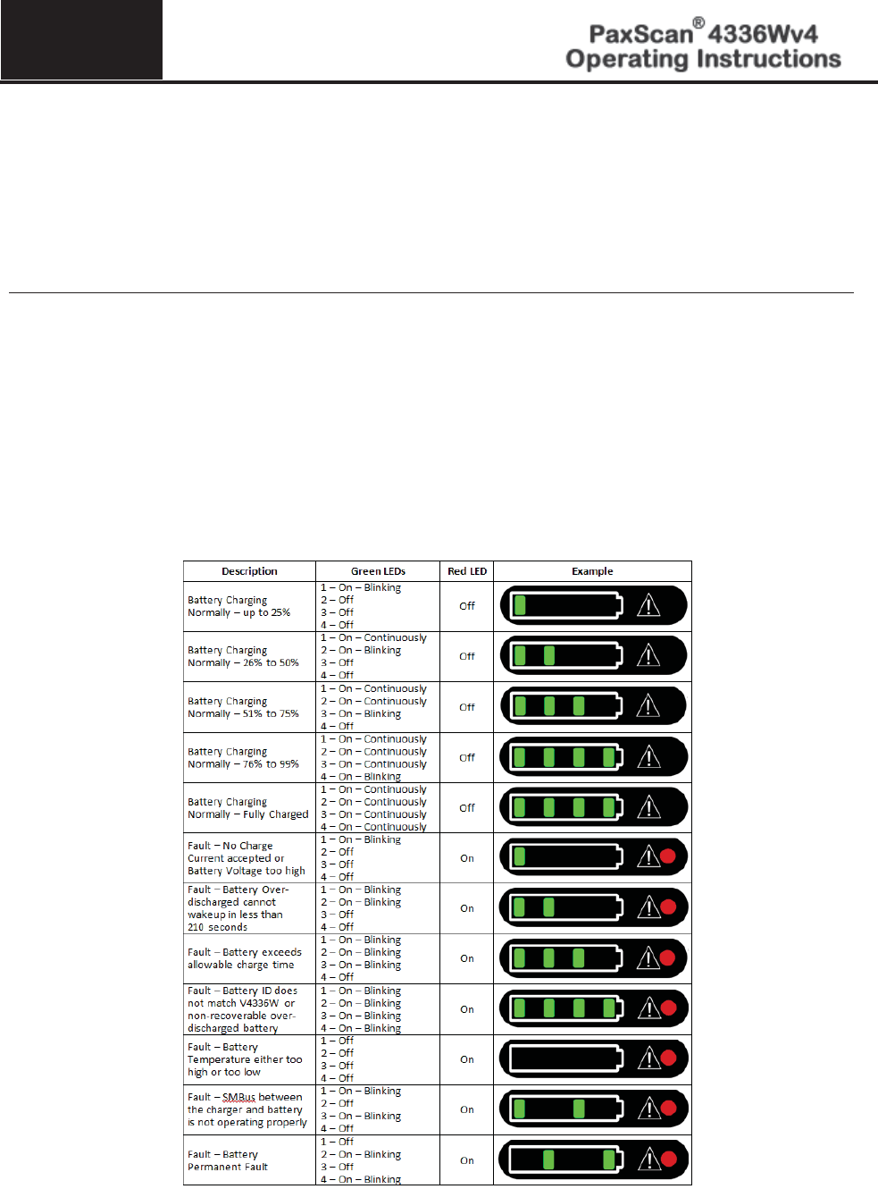
Battery charging using the stand alone 3-Bay Battery Charger
The Varian 3-bay charger requires
1. 24V DC, 3.3A max input.
2. The output of the charger is 16.8V DC, 1.5A max (+/1 1% and 10 Hz).
Step
Action / Results
1.
Hold battery on end opposite of the contacts with the contacts facing toward the charger.
2.
Gently slide battery into battery compartment on the charger. When properly inserted, a light
next to the battery slot will turn on showing the charge status of the battery. When the battery
is charging the light will be orange, when charging is complete the light will turn green and
when there is a fault the light will be red.
Charging a fully discharged battery will take 3.5 hours maximum and 2.5 hours typical when
operating at room temperature. Up to three batteries can be charged at a time. Refer to below
Figure B-1 for explanation of LED status indicators.
Figure A-1 3-Bay Battery Charger Status Indicators
11
© Varian Medical Systems | X-Ray Products
51
Battery charging using the stand alone 1-Bay Battery Charger
The Varian 1-bay charger requires:
1. 19V DC, 2.1A max input.
2. The output of the charger is 16.8V DC, 1.4A max (+/-1% and 10 Hz).
Step
Action / Results
1.
The Varian battery communicates with the Varian 1-bay charger when it is plugged into the
charger. The battery monitors its readiness state and is mechanically
keyed to charger for easy
installation.
2.
The charger provides the following LED indicators to identify charge process and charge faults
(see below
Figure B-2).
x When all four (4) green LEDs are continuously illuminated (with the red LED
off), the battery has reached maximum charge. It can either be removed or left
in the charger to maintain full charge. Charging time typically is 2.5 hours,
maximum 3.5 hours.
Figure A-2 1-Bay Battery Charger Status Indicators

11
© Varian Medical Systems | X-Ray Products
52
Warning:
Do not remove the charger cover. The Charger has no internal user
serviceable parts.
Warning:
Do not use in operating room or other oxygen rich environment.
Do not use in conjunction with flammable agents.
Do not use in an environment with condensing moisture.
Caution:
Do not use flowing liquid or immersion on the receptor, battery, battery
compartment, or battery charger.
Do not sterilize.
Caution:
Do not attempt to insert objects other than the Varian battery into the
charger bay.
Important:
Use the Varian Battery Charger only with the Varian supplied power
supply and power cord.
Important:
Use only the Varian supplied batteries in the battery charger and
receptor. The systems are not designed to work in conjunction with
any other battery type or design.