Vecima Networks 915A Radio Module User Manual Manual
Vecima Networks Inc. Radio Module Manual
Manual
LMS3000 Technical
Note
Lawrence Gordon Page 1 of 8 Last saved on 27-Mar-06 5:45 PM
F:\Tech Notes\TN131C - 915A Radio Operational Requirements.doc
Number: TN131C
Title: 915A Radio Operational Requirements
Author: Lawrence Gordon
Reviewer:
Date: 27-Mar-06
Pages: 8
Abstract:
This document lists the requirements that must be met in order to use the WaveRider 915A
Radio in different packages and configurations.
Revision History:
Date Rev. Author Comments
24 Mar
‘06
A L.
Gordon
Initial Approval for AC to 4.2 VDC power supply; Indoor, and YAGI antennas
27 Mar
‘06
B L.
Gordon
Add FCC / IC Warnings, indicate that Radio Module can only to be installed by
WaveRider manufacturers
27 Mar.
‘06
C L.
Gordon
Correct Antenna gain

TN131C 915A Radio Operational Requirements
Lawrence Gordon Page 2 of 8 Last saved on 27-Mar-06 5:45 PM
F:\Tech Notes\TN131C - 915A Radio Operational Requirements.doc
Table of Contents
1 Introduction........................................................................................................................ 3
1.1 References ................................................................................................................ 3
2 Requirements....................................................................................................................3
2.1 Regulatory Notices Requirements ............................................................................ 3
2.1.1 FCC.................................................................................................................... 4
2.1.2 Industry Canada ................................................................................................ 5
2.1.3 Installation Warnings ......................................................................................... 5
2.2 Final Product Installation Guide Requirements ........................................................ 5
2.3 Final Product Labeling Requirements....................................................................... 6
2.4 Power Supplies ......................................................................................................... 6
2.5 Antennas ................................................................................................................... 7
2.6 External RF Connectors............................................................................................ 7
3 Approved Configurations .................................................................................................. 8
3.1 Approved Power Supplies......................................................................................... 8
3.2 Approved Antennas................................................................................................... 8
Table of Tables
Table 1 – Approved Power Supplies........................................................................................ 8
Table 2 – Approved Antennas.................................................................................................. 8

TN131C 915A Radio Operational Requirements
Lawrence Gordon Page 3 of 8 Last saved on 27-Mar-06 5:45 PM
F:\Tech Notes\TN131C - 915A Radio Operational Requirements.doc
Appendix A1 INTRODUCTION
The WaveRider 915A Radio is certified by FCC and Industry Canada (IC) under a Limited
Modular Approval (FCC ID: OOX-915A and IC ID: 3225B-915A). This means that the radio
can be used in various packages and configurations provided the requirements below are met.
These requirements apply to any WaveRider final product using the 915A radio.
Note that this radio under the 915A certifications cannot be sold as a bare board to end-
customers or OEMs. Only WaveRider manufactured final products can be sold. As such, this
document is intended only for WaveRider or its contractors to act as an ‘installation guide’ for
installing the 915A radio into a final product.
Adhering to these requirements will not necessarily ensure compliance to FCC and IC
requirements for the final product. If there are any concerns, testing should be done to ensure
compliance. For example, the 915A radio meets the FCC and IC Class B unintentional radiator
requirements as a standalone unit. If it is combined with other components or radios, the
aggregate may not meet the same limits as the standalone unit.
The term “final product” in this document will refer to the product that is sold that incorporates
the 915A radio. WaveRider products that use the 915A radio currently includes the EUM2005.
This document will be updated as new configurations are approved for the 915A radio, such as
new antenna and power supplies.
The approved configurations are shown in Section 3.
WARNING – Final product (e.g. EUM3005, MMT9000, etc.) user documentation (e.g.
Installation Guides, Spec. Sheets) must NOT contain any information about how the 915A radio
is installed in the final product nor how to access the radio.
A.11.1 References
LMA PART 15 UNLICENSED MODULAR TRANSMITTER APPROVAL, DA 00-1407, June 26,
2000.
Part 15 FCC CFR 47 Part 15 - RADIO FREQUENCY DEVICES, April 5, 2005.
Appendix B2 REQUIREMENTS
2.1 Regulatory Notices Requirements
Regulatory Notices
This equipment has been tested and found to comply with the limits for a Class B Intentional
Radiator, pursuant to Part 15 of the FCC Regulations. These limits are intended to provide pro-
tection against harmful interference when the equipment is operated in a residential environment.
This equipment generates, uses, and can radiate radio frequency energy and, if not installed and
used in accordance with the instruction manual, may cause harmful interference to radio
communications. However, there is no guarantee that interference will not occur in a particular
installation.

TN131C 915A Radio Operational Requirements
Lawrence Gordon Page 4 of 8 Last saved on 27-Mar-06 5:45 PM
F:\Tech Notes\TN131C - 915A Radio Operational Requirements.doc
All versions of this device have been tested using unshielded Ethernet CAT-5 cable.
Notice to User
Any changes or modifications to equipment that are not expressly approved by WaveRider may
void the user’s authority to operate the equipment.
2.1.1 FCC
The 915A radio has been designed and manufactured to comply with FCC Part 15 under FCC
ID: OOX-915A.
Operators must be familiar with the requirements of the FCC Part 15 Regulations prior to
operating any link using this equipment. For installations outside the United States, contact local
authorities for applicable regulations.
Note: This equipment has been tested and found to comply with the limits for a Class B digital
device, pursuant to part 15 of the FCC Rules. These limits are designed to provide reasonable
protection against harmful interference in a residential installation. This equipment generates,
uses and can radiate radio frequency energy and, if not installed and used in accordance with the
instructions, may cause harmful interference to radio communications. However, there is no
guarantee that interference will not occur in a particular installation. If this equipment does cause
harmful interference to radio or television reception, which can be determined by turning the
equipment off and on, the user is encouraged to try to correct the interference by one or more of
the following measures:
• Reorient or relocate the receiving antenna.
• Increase the separation between the equipment and receiver.
• Connect the equipment into an outlet on a circuit different from that to which the receiver
is connected.
• Consult the dealer or an experienced radio/TV technician for help.
Interference Environment
Operation is subject to the following conditions:
• This device may not cause harmful interference and,
• This device must accept any interference received, including interference that might
cause undesired operation.
Operational Requirements
In accordance with the FCC Part 15 regulations:
1. The maximum average power output of the intentional radiator shall not exceed one (1)
watt (30 dBm) for all spread spectrum systems operating in the 902 to 928MHz band.
2. Stations operating in the 902 to 928MHz band may use transmitting antennas of
directional gain greater than 6dBi, provided the average output power from the
intentional radiator is reduced by the amount in dB that the directional gain of the
antenna exceeds 6dBi.

TN131C 915A Radio Operational Requirements
Lawrence Gordon Page 5 of 8 Last saved on 27-Mar-06 5:45 PM
F:\Tech Notes\TN131C - 915A Radio Operational Requirements.doc
3. The operator of a spread spectrum system and the user of the radio device are each
responsible for ensuring that the system is operated in the manner outlined in the section
on Interference Environment above.
The 915A radio with its certified antennas complies with these requirements when installed
correctly as detailed in this manual.
2.1.2 Industry Canada
The 915A radio has Industry Canada (IC) Certification Number 3225B-915A.
Operators must be familiar with IC RSS-210 and RSS-102. The 915A has been designed and
manufactured to comply with IC RSS-210 and RSS-102.
This device has been designed to operate with the antennas listed below and having a maximum
antenna system gain of 8.7dB. Antennas not included in this list or having a gain greater than 8.7
dB are strictly prohibited for use with this device. The required antenna impedance is 50 ohms.
To reduce potential radio interference to other users, the antenna type and its gain should be so
chosen that the equivalent isotropically radiated power (e.i.r.p.) is not more than that permitted
for successful communication.
2.1.3 Installation Warnings
It is the responsibility of the operator to ensure that the public is not exposed to excessive Radio
Frequency (RF) levels. The applicable regulations can be obtained from local authorities.
WARNING
To comply with FCC RF exposure limits, the Indoor Antenna must be fix-mounted
indoors to provide a separation distance of 20cm (8 inches) or more from all persons
to satisfy RF exposure requirements. The outdoor antennas are to be fix-mounted to
provide a separation distance of 30 cm (1 ft.) or more from all persons to satisfy RF
exposure requirements. The distance is measured from the nearest point of the
modem to the human body. It is recommended that the modem be installed in a
location with minimal pathway disruption by nearby personnel.
WARNING
Outdoor antennas must be professionally. The installer must understand
applicable FCC or Industry Canada rules regarding antennas. Only the
approved antenna types with gains up to the specified maximum can be used
with the 915A Radio and its final products. Installer must also understand and
follow electrical codes that apply to installing outdoor antennas.
2.2 Final Product Installation Guide Requirements
The following notices must appear in any ‘final product’ installation guides as well as applying
to the 915A radio itself. As well, the text of sections 2.1.1, 2.1.2, and 2.1.3 apply to the 915A
TN131C 915A Radio Operational Requirements
Lawrence Gordon Page 6 of 8 Last saved on 27-Mar-06 5:45 PM
F:\Tech Notes\TN131C - 915A Radio Operational Requirements.doc
radio and any of its final products and should be included in any final product installation guide,
edited as appropriate (e.g. use final product name rather than 915A Radio).
The regulatory notices in sections 2.1.1, 2.1.2, and 2.1.3 must be included in the installation
guide for the final product edited as appropriate (e.g. use final product name rather than 915A
Radio). As well, the final product installation guide must provide NO instructions on how to
remove the 915A radio from the product. The following notices should be included to make this
clear:
This product contains no user-serviceable parts. Opening this product will void any warranty.
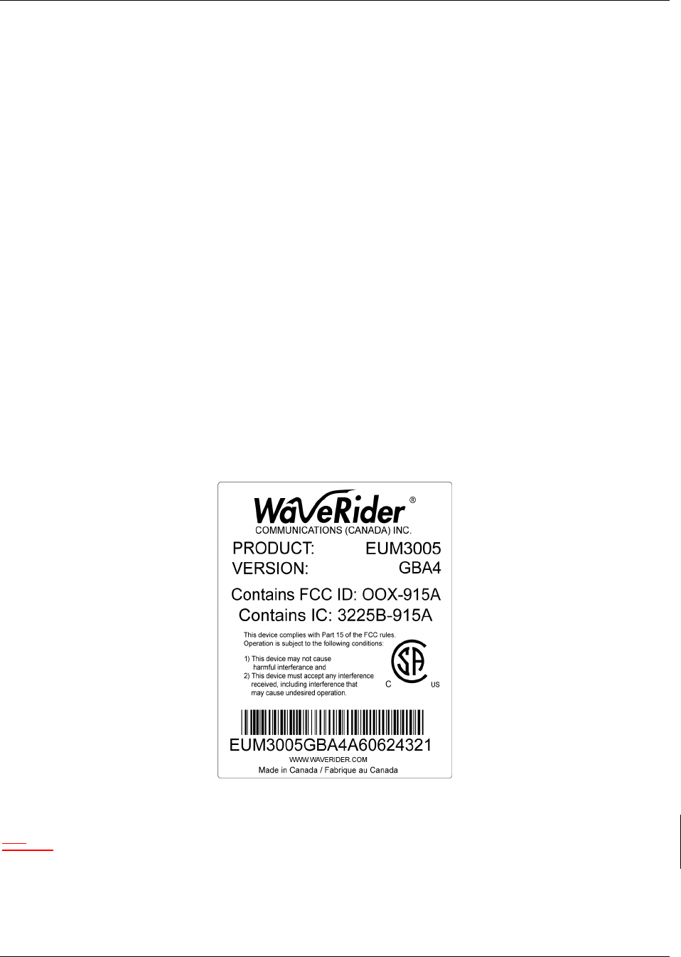
2.3 Final Product Labeling Requirements
The final product must have a permanent label that contains the following text:
“Contains FCC ID: OOX-915A” and
“Contains IC: 3225B-915A”.
If the label has room, then the statement “This device complies with Part 15 of FCC rules” plus
the text from the Interference Environment sub-section of 2.1.1 should be included.
The following picture shows the WaveRider standard label that is recommended for all products
containing the 915A radio, edited as appropriate.
B.12.4 Power Supplies
The 915A radio is approved by FCC and IC using specific AC/DC converters. The currently
approved converter is the Fairway WVG 10F-420A, AC to 4.2 VDC power supply. The use of
any other AC power supply requires testing to ensure it complies with FCC and IC rules on
Conducted Limits on AC lines (e.g. [Part 15] 15.207).

TN131C 915A Radio Operational Requirements
Lawrence Gordon Page 7 of 8 Last saved on 27-Mar-06 5:45 PM
F:\Tech Notes\TN131C - 915A Radio Operational Requirements.doc
If the 915A radio is powered by a supply other than the AC lines (e.g. vehicle power) then no
testing is required.
B.22.5 Antennas
Only antennas that have been approved by FCC and IC shall be used with the 915A radio. This
means that any antenna of the same family with a gain less than or equal to the approved antenna
can be used.
The list of approved antennas is given in Appendix A, which will be updated as new antennas are
approved.
The 915A radio is initially approved with the WaveRider Indoor Diversity Antenna (4.4 dBi) and
a YAGI (13 dBi).
However, the 915A radio is approved for 27.3 dBm output power at the antenna port and FCC
and IC rules require the peak radiated power be no more than 36 dBm, so a maximum of 8.7 dB
gain is allowed for the antenna system, which includes the antenna gain in dBi and any losses
between the 915A radio and the antenna, including cable losses, insertion losses at filters and
surge protectors etc.
Therefore if a 13 dBi YAGI antenna is used, then the losses must be at least 4.3 dB (27.3 + 13 –
4.3 = 36 dBm). A rule of thumb is that the losses must equal Antenna Gain (dBi) – 8.7.
This information shall be clearly noted in any installation manual for the final product.
It is also required that warnings be included in the installation manual regarding separation of
people from the antennas.
• Indoor antennas are limited to gains of 7.5 dBi or less, including cable losses. This limts
the totoal EIRP to 34.8 dBm. Indoor antennas must be installed so that people are at least
20 cm from the antenna under normal conditions. The WaveRider Indoor Diversity
Antenna meets these requirements.
• Outdoor antennas can support the full total gain of 8.7 dBi for the antenna system, for a
maximum EIRP of 36 dBm. Outdoor antennas must be installed so that people are
normally at least 30 cm from the antenna.
B.32.6 External RF Connectors
The 915A radio can be manufactured by WaveRider with a variety of external RF connection
options. The following requirements apply:
• WaveRider proprietary, unique external connector – This connector is externally
accessible and can be used on any final product.
• No RF connector – Final products with an integrated, approved antenna (i.e. no RF
connector externally accessible).
• Standard external RF Connectors (e.g. SMA or N type) – Final products that have
standard externally accessible RF connectors can only be installed by professionals. The
installation guide for these products must make this clear. The guide must provide
sufficient instruction to the installer for a successful installation.
TN131C 915A Radio Operational Requirements
Lawrence Gordon Page 8 of 8 Last saved on 27-Mar-06 5:45 PM
F:\Tech Notes\TN131C - 915A Radio Operational Requirements.doc
Appendix A3 APPROVED CONFIGURATIONS
A.13.1 Approved Power Supplies
Table 1 – Approved Power Supplies
# Power Supply Voltage Comments
1 Fairway WVG 10F-420A AC to 4.2 VDC
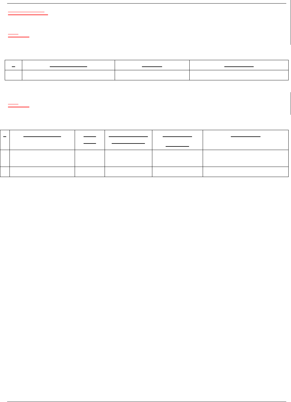
A.23.2 Approved Antennas
Table 2 – Approved Antennas
# Antenna Type Max.
Gain
Required Loss
@ max. gain
Separation
Distance
Comments
1 WaveRider Indoor
Diversity
4.4 dBi 0 20 cm Approved for indoor use.
2 YAGI 13 dBi 4.3 dB 30 cm Outdoor antenna