Vecima Networks AMG1020X Truckerlink Advanced Mobile Gateway User Manual amg ins bhxkit incab ml r05 sd
Vecima Networks Inc. Truckerlink Advanced Mobile Gateway amg ins bhxkit incab ml r05 sd
UserManual.wiki
>
Vecima Networks
>
AMG1020X User Manual
User Manual
Navigation menu
Upload a User Manual
Namespaces
Wiki Guide
HTML
PDF
Info
Views
User Manual
Discussion / Help
Navigation
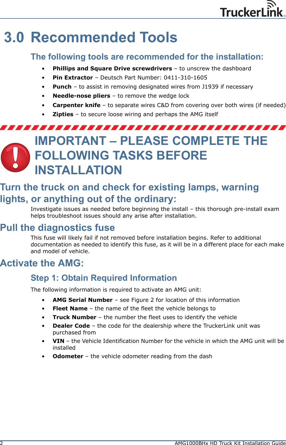
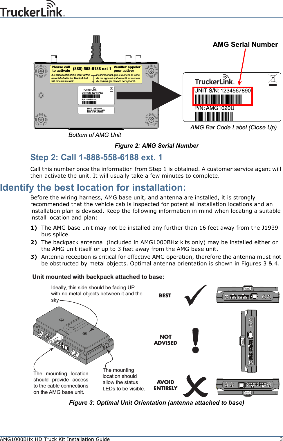
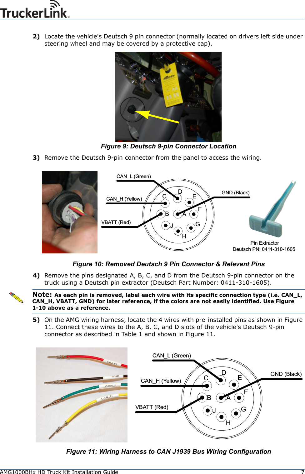
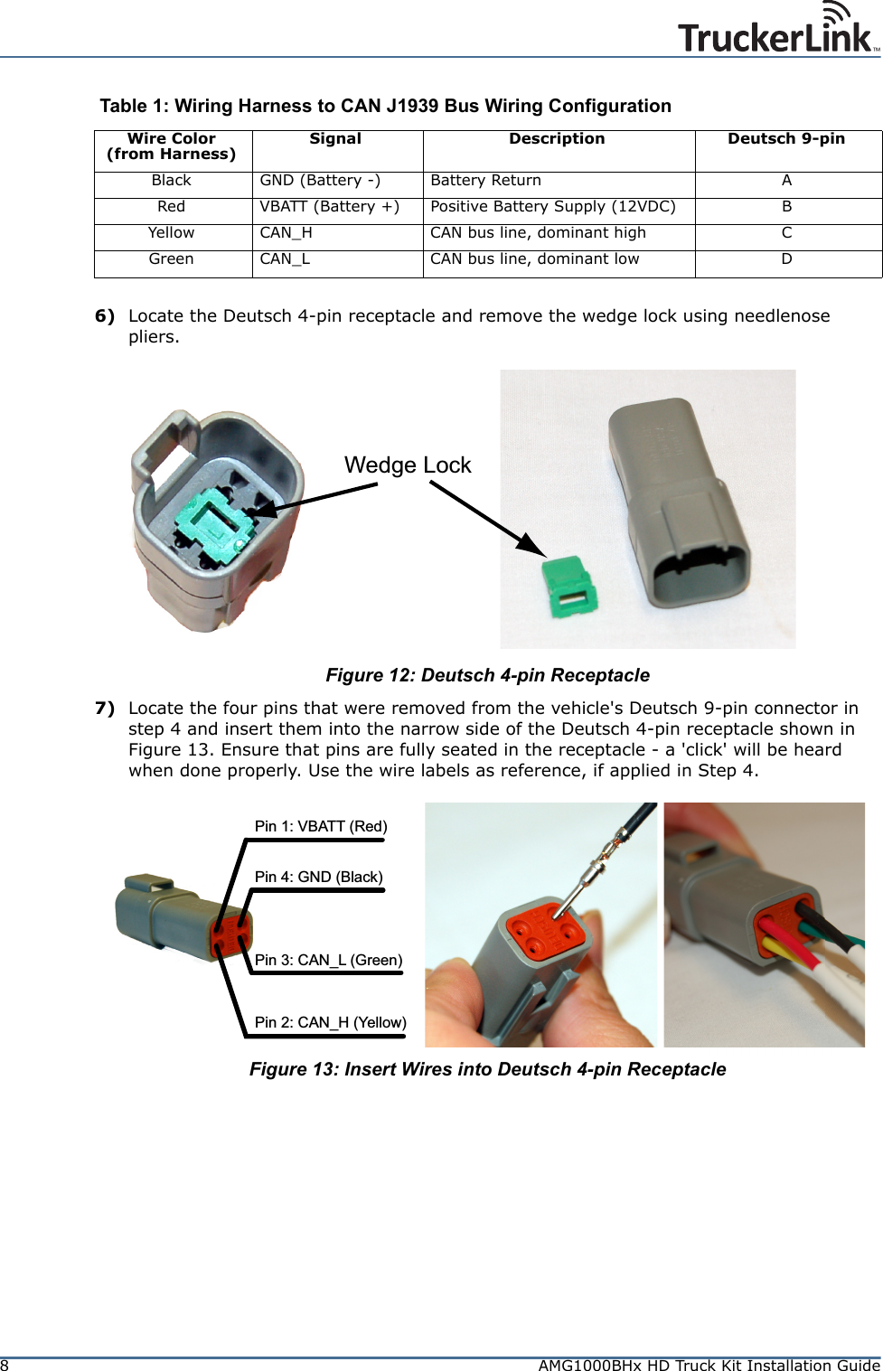
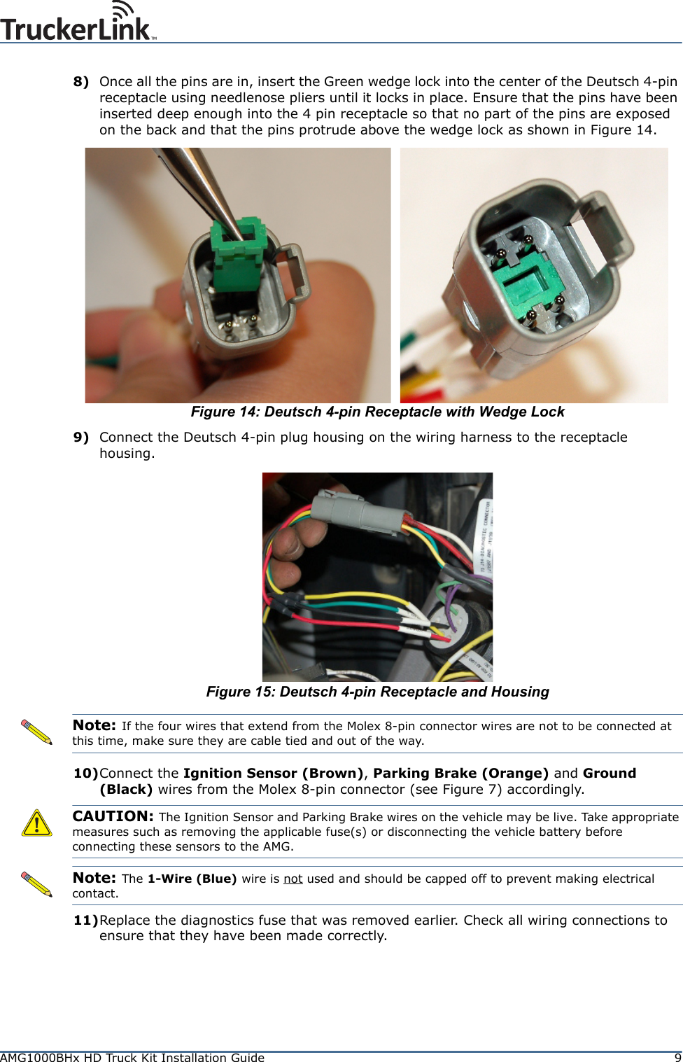
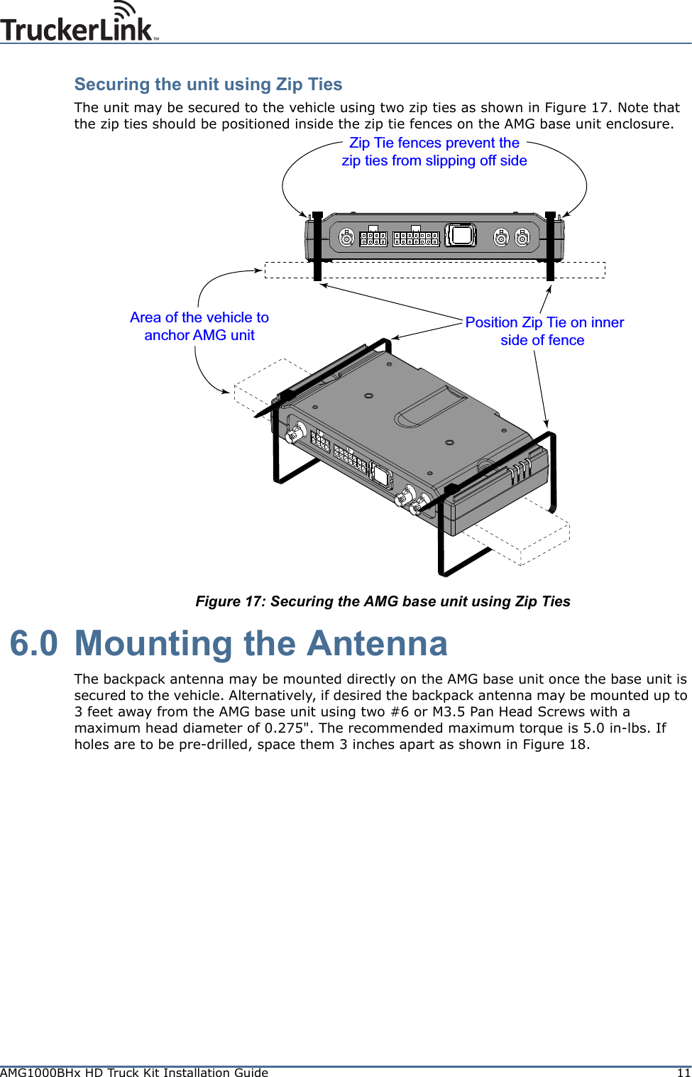
![6AMG1000BHx HD Truck Kit Installation GuideWiring Harness Installation OverviewFigure 7 shows the wiring harness installation overview. The following section provides the detailed installation instructions.Figure 7: Wiring Harness Installation Overview 4.3 Wiring Harness Installation Steps1) Remove dashboardFigure 8: Remove Dashboard4312Deutsche 4-PinReceptacleDeutsche 9-PinConnectorJ1939 Busfrom EngineDeutsche 9-PinConnectorJ1939 Busfrom EnginePinout:1 = VBATT2 = CAN_H3 = CAN_L4 = GNDDeutsche 4-PinIn-Line ConnectorRemove pins from Deutsche9-Pin Connector in vehicledashboard and attach toDeutsche 4-Pin Receptacle1243VBATT (Red)GND (Black)CAN_H (Yellow)CAN_L (Green)Vehicle DashboardParking Brake (Orange)Ignition Sensor (Brown)1-Wire (Blue) [NOT USED]Ground (Black)Molex MiniFit ConnectorPlugs into AMG base unit 12 4356 875 = 1-Wire6 = CAN_L7 = CAN_H8 = VBATTPinout:1 = GND2 = Ignition Sensor3 = Parking Brake4 = GND (Battery -)WIRING HARNESSVehicle DashboardAttach pins fromwiring harness toDeutsche 9-PinConnectorAMG base unit (Connector Side)BEFORE AMG WIRING HARNESS IS INSTALLEDAFTER AMG WIRING HARNESS IS INSTALLED](https://usermanual.wiki/Vecima-Networks/AMG1020X/User-Guide-1606897-Page-6.png)