Vecima Networks BTR5857 BTR5857 User Manual USERS GUIDE
Vecima Networks Inc. BTR5857 USERS GUIDE
UserManual.wiki
>
Vecima Networks
>
BTR5857 User Manual
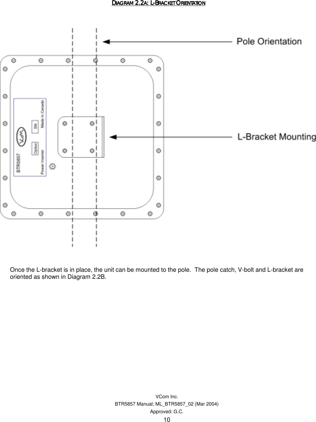
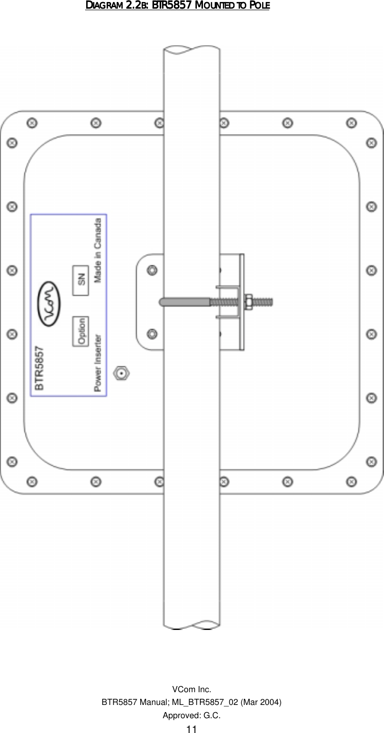
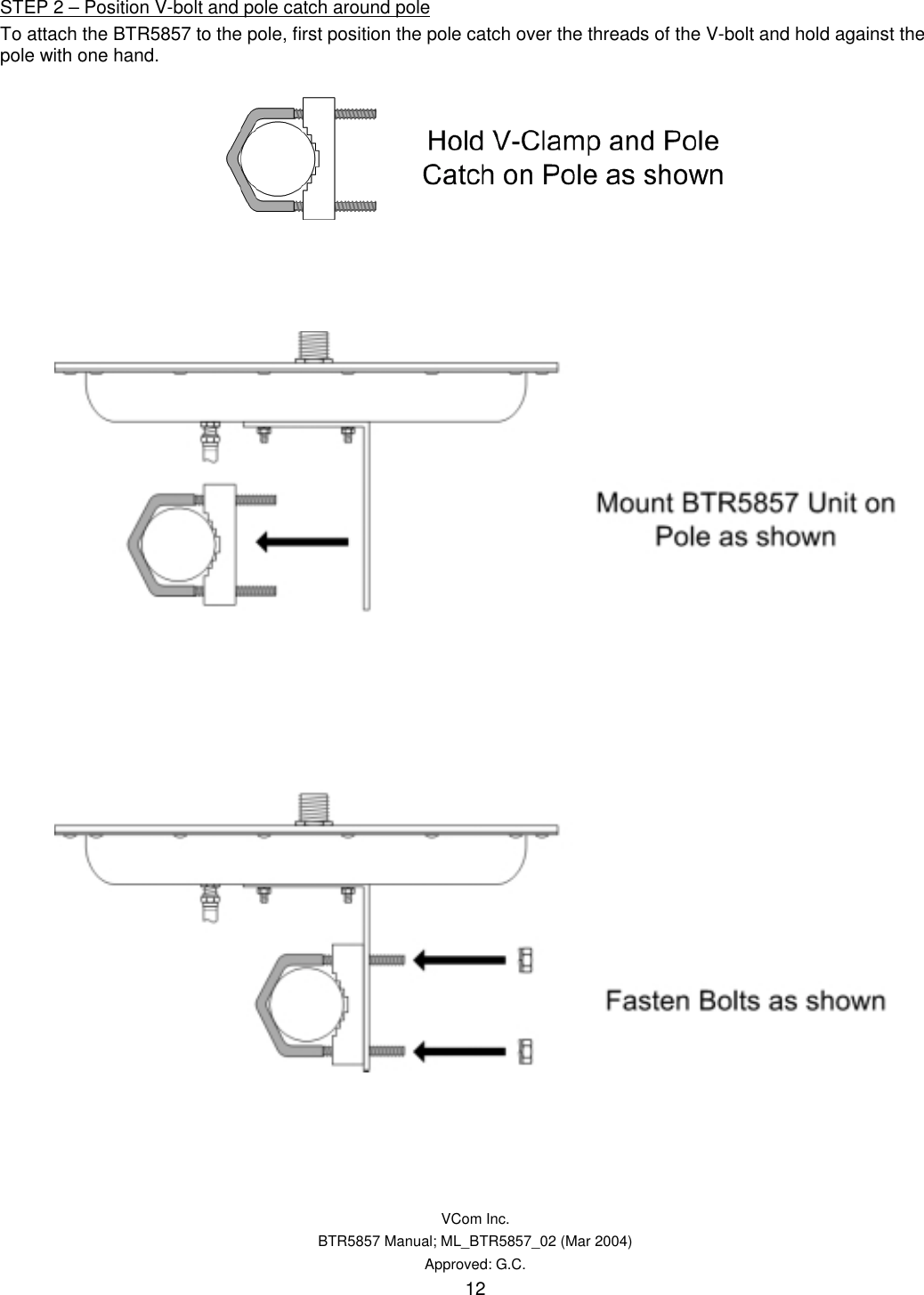
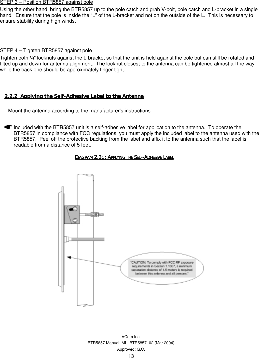
USERS GUIDE
Navigation menu
Upload a User Manual
Namespaces
Wiki Guide
HTML
PDF
Info
Views
User Manual
Discussion / Help
Navigation