Vecima Networks OBR3650 VistaMAX OBR3650 3.65 GHz Station Transceiver User Manual obr3650 ml 01 sd
Vecima Networks Inc. VistaMAX OBR3650 3.65 GHz Station Transceiver obr3650 ml 01 sd
Contents
- 1. Users Manual part1
- 2. Users Manual part2
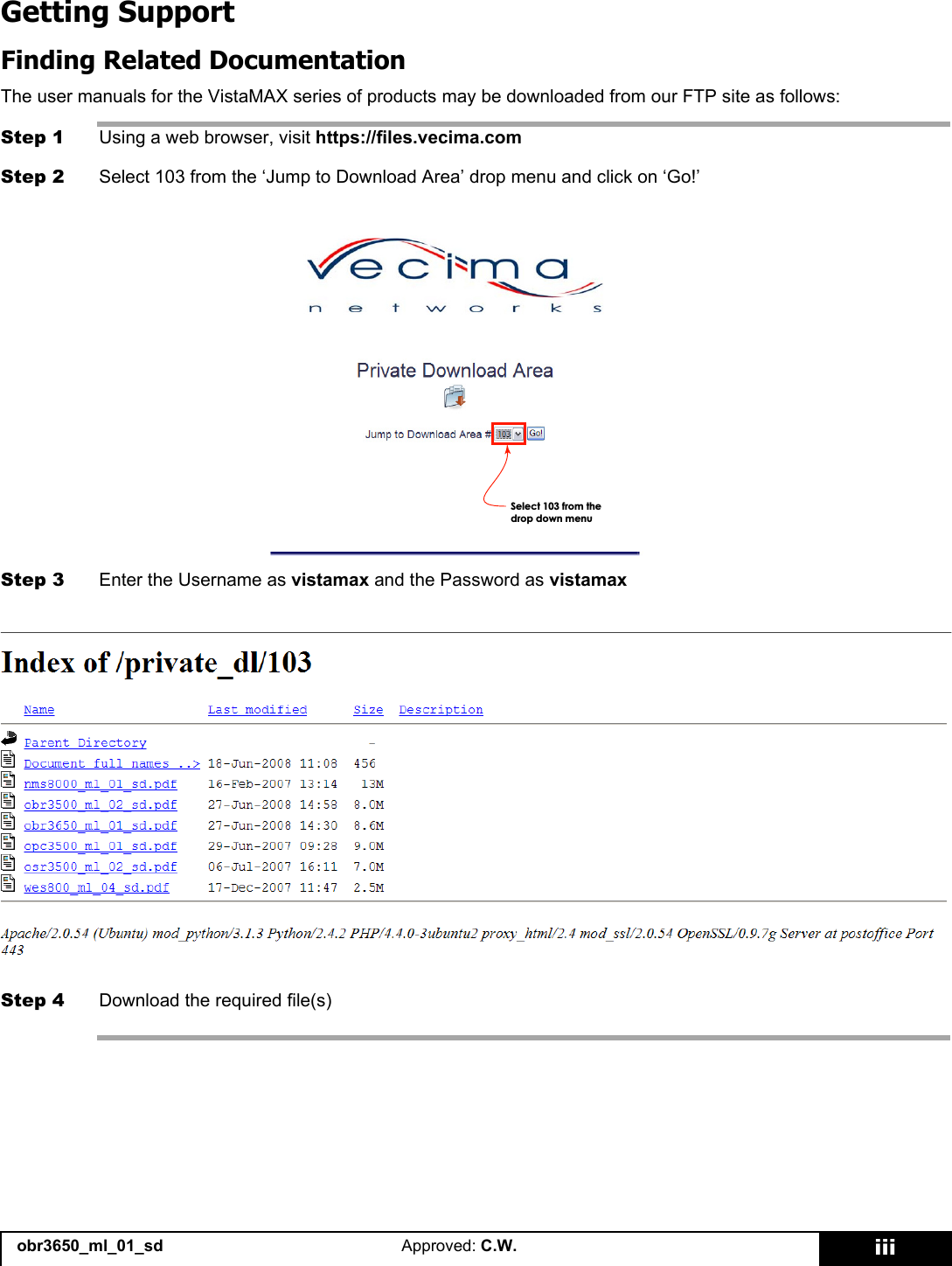
Users Manual part1
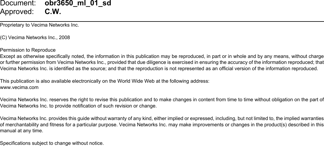


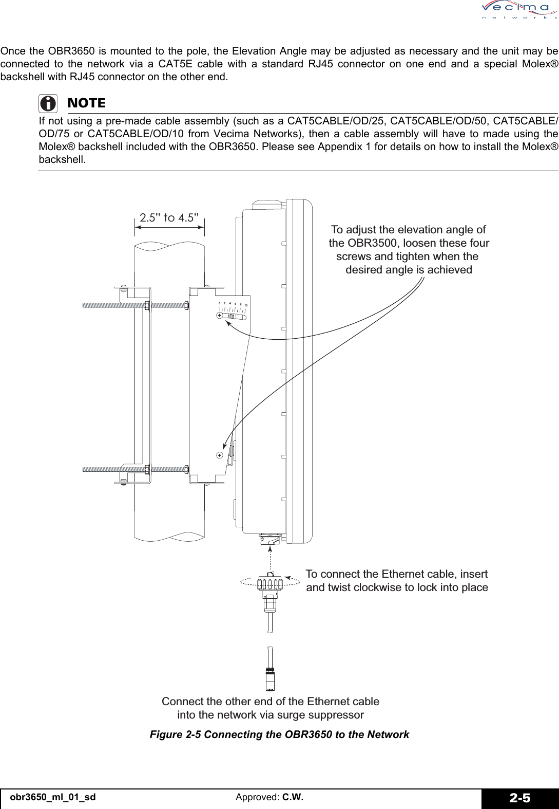
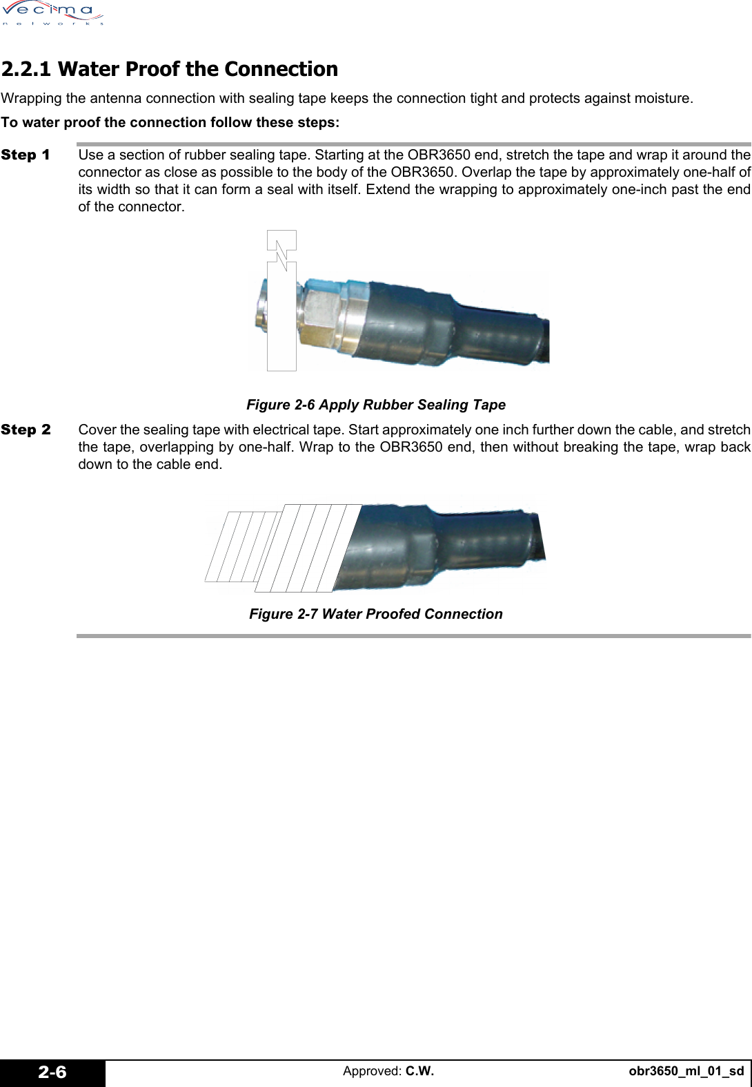
![obr3650_ml_01_sd Approved: C.W. 2-72.3 Installing the Grounding ApparatusInstall the grounding apparatus to protect the OBR3650 from lightning strikes and power surges. Ground the basestation to the earth ground to protect from lightning strikes. Use the surge suppressor to shunt to ground any over-voltage [>60 V] transients that may be induced on the CAT5E cablefeed via lightning or other high voltages. 2.3.1 Lightning ProtectionThe OBR3650 has a built in lightning surge suppression mechanism to protect it against damage from lightning strikes.Assembling the OBR3650 Base Station GroundingAttach the earth ground to the grounding lug located on the base station.Provided parts:• 1 x 5/8 inch washer• 1 x 1/4 inch grounding lugRequired parts:• 1 x #6 AWG grounding wire assembly of sufficient length to connect the OBR to the tower’s earth ground bus• 1 Size 11 Wrench (11mm or 7/16 inch)To assemble and attach the ground lug:1. Locate the grounding point on the OBR3650. This is at the bottom of the OBR, to the right of the Vecima sticker.2. On the grounding lug, assemble the grounding combination in the following order: Lug > Washer > Grounding Assembly > Washer.3. Screw the combination into the OBR at the grounding point.4. Attach the assembly to the lightning grid or the antenna.Figure 2-8 Assembled Ground Lug](https://usermanual.wiki/Vecima-Networks/OBR3650.Users-Manual-part1/User-Guide-985961-Page-21.png)
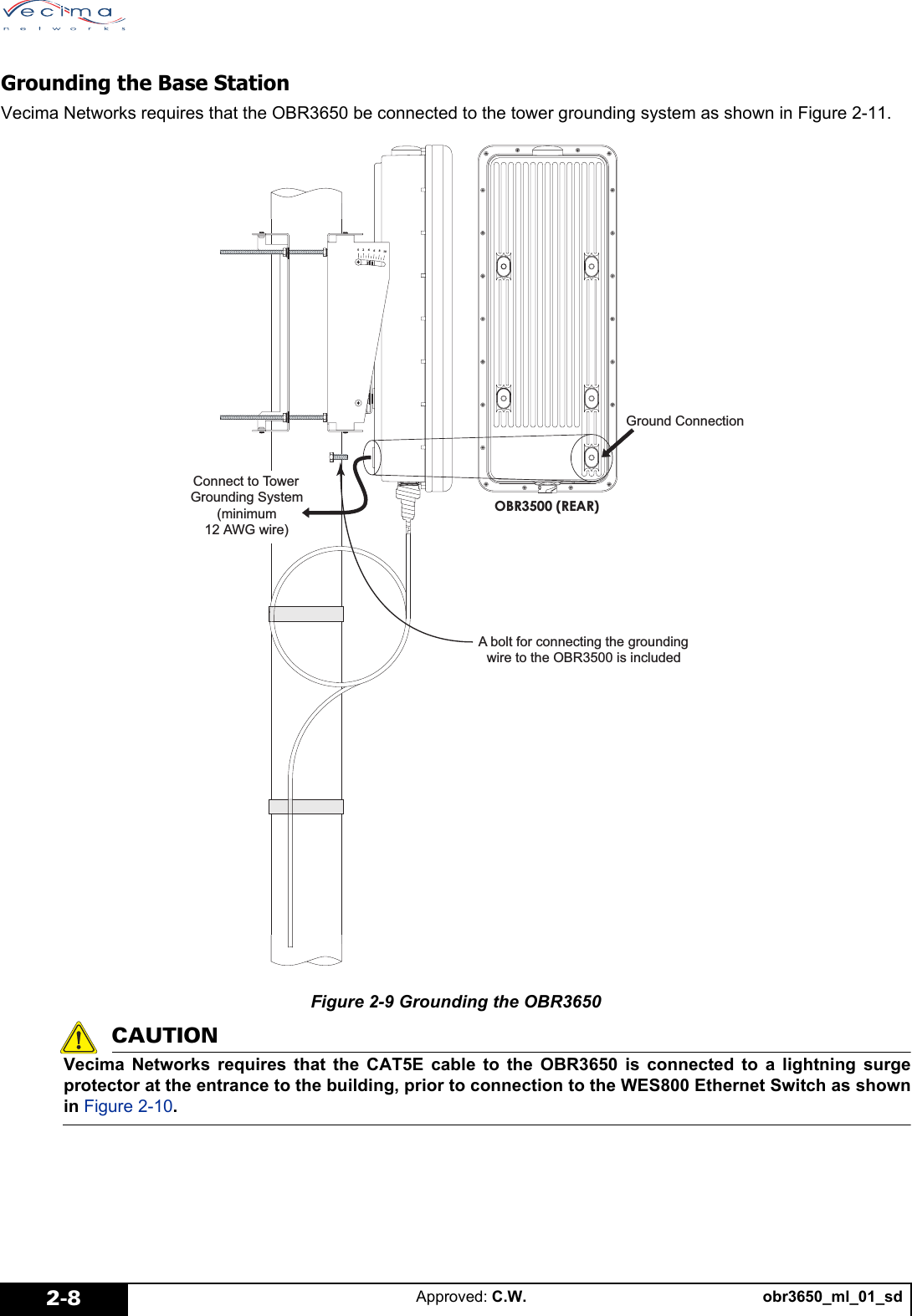

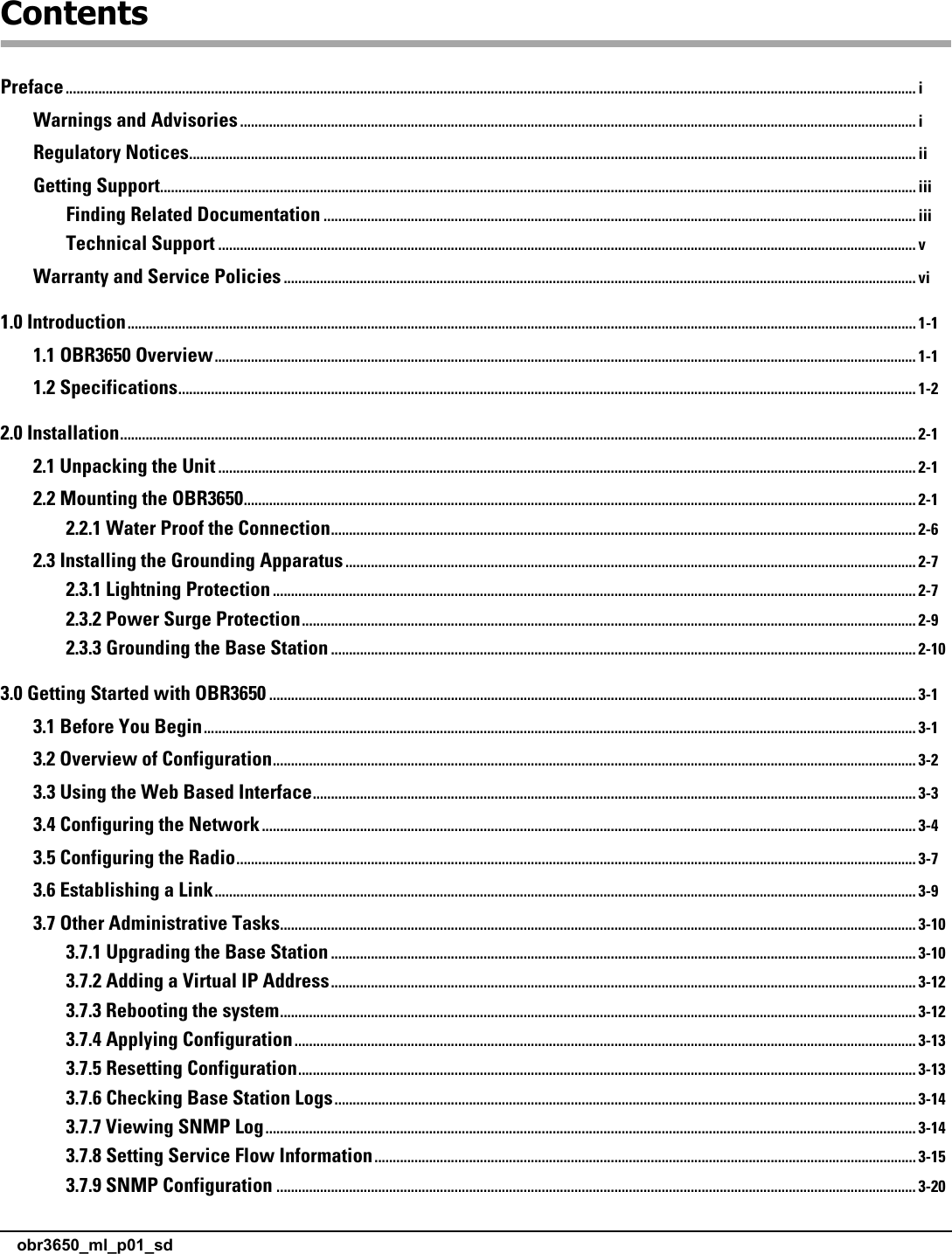
![obr3650_ml_01_sdApproved: C.W.2-102.3.3 Grounding the Base StationVecima recommends grounding the base station using one of the following procedures depending on your configuration.If you are unsure which procedure to use, use procedure B.Procedure A: Grounding the base station so that the building and the tower share thesame earth ground:1. Connect the chassis of the OBR3650 to the tower via the grounding lug on the back of the unit. See “2.3.3 Grounding the Base Station”.2. Use a shielded CAT5 cablefeed to connect the OBR base station to the surge suppressor.3. Use an inline surge suppressor for all OBR3650 cablefeed installations. Connect the shield of the cablefeed to the ground lug of the surge suppressor. The purpose of the surge suppressor is to shunt to ground any over voltage [>60] transients that may be induced on the CAT5E cablefeed via lightning or other high voltages.Figure 2-11 Base Station Grounding - building ground is same as tower ground](https://usermanual.wiki/Vecima-Networks/OBR3650.Users-Manual-part1/User-Guide-985961-Page-24.png)
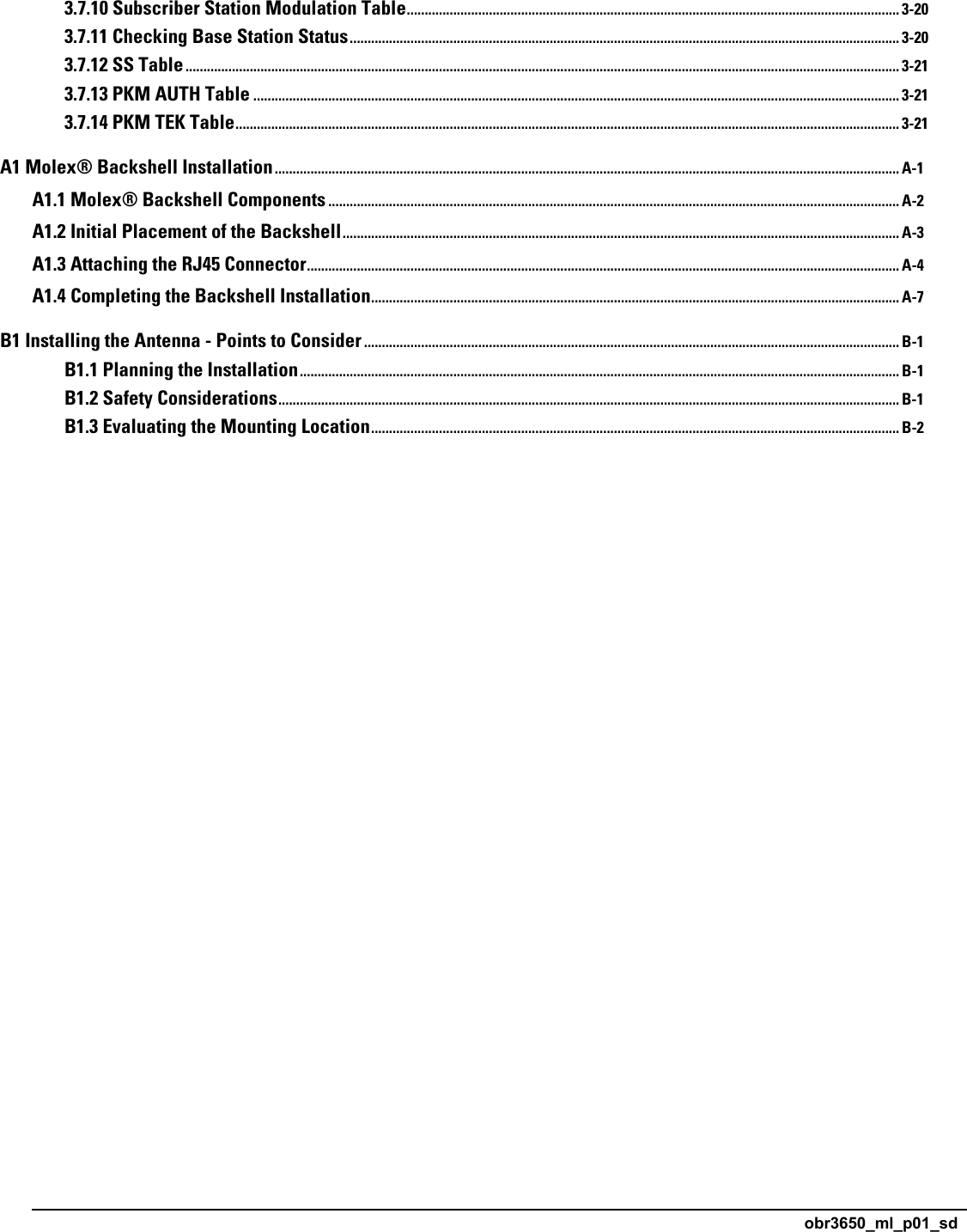
![obr3650_ml_01_sd Approved: C.W. 2-11Procedure B: Grounding the base station so that the building and the tower usedifferent earth grounds:1. Connect the chassis of the OBR3650 to the tower via the grounding lug on the back of the unit. See “2.3.3 Grounding the Base Station”.2. Use a shielded CAT5 cablefeed to connect the OBR base station to the surge suppressor.3. Use two inline surge suppressors, one for all OBR3650 cablefeed installations at the base of the tower and another for the first surge suppressor and the WES800. Connect the shield of the cablefeed to the ground lug of the surge suppressor. The purpose of the surge suppressor is to shunt to ground any over voltage [>60 V] transients that may be induced on the CAT5E cablefeed via lightning or other high voltages.Figure 2-12 Base Station Grounding - building ground different than tower ground](https://usermanual.wiki/Vecima-Networks/OBR3650.Users-Manual-part1/User-Guide-985961-Page-25.png)