Vecima Networks OBR5000B 5 GHz Base Station Transceiver User Manual obr5000b ml r01 sd
Vecima Networks Inc. 5 GHz Base Station Transceiver obr5000b ml r01 sd
UserManual.wiki
>
Vecima Networks
>
OBR5000B User Manual
User Manual
Navigation menu
Upload a User Manual
Namespaces
Wiki Guide
HTML
PDF
Info
Views
User Manual
Discussion / Help
Navigation
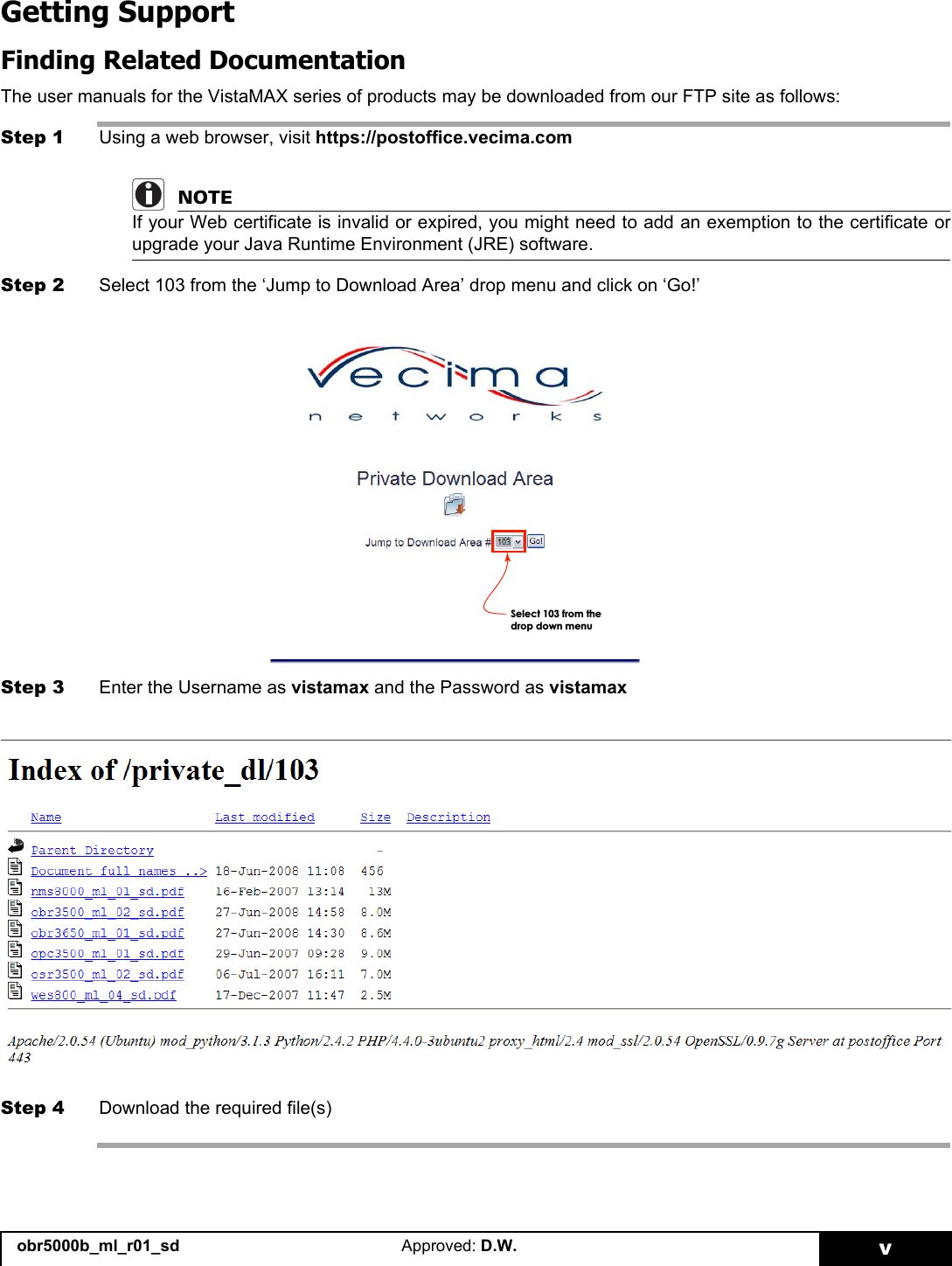
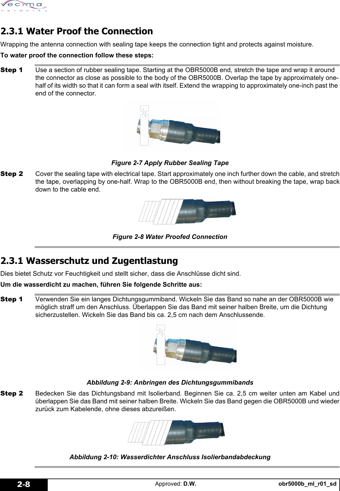
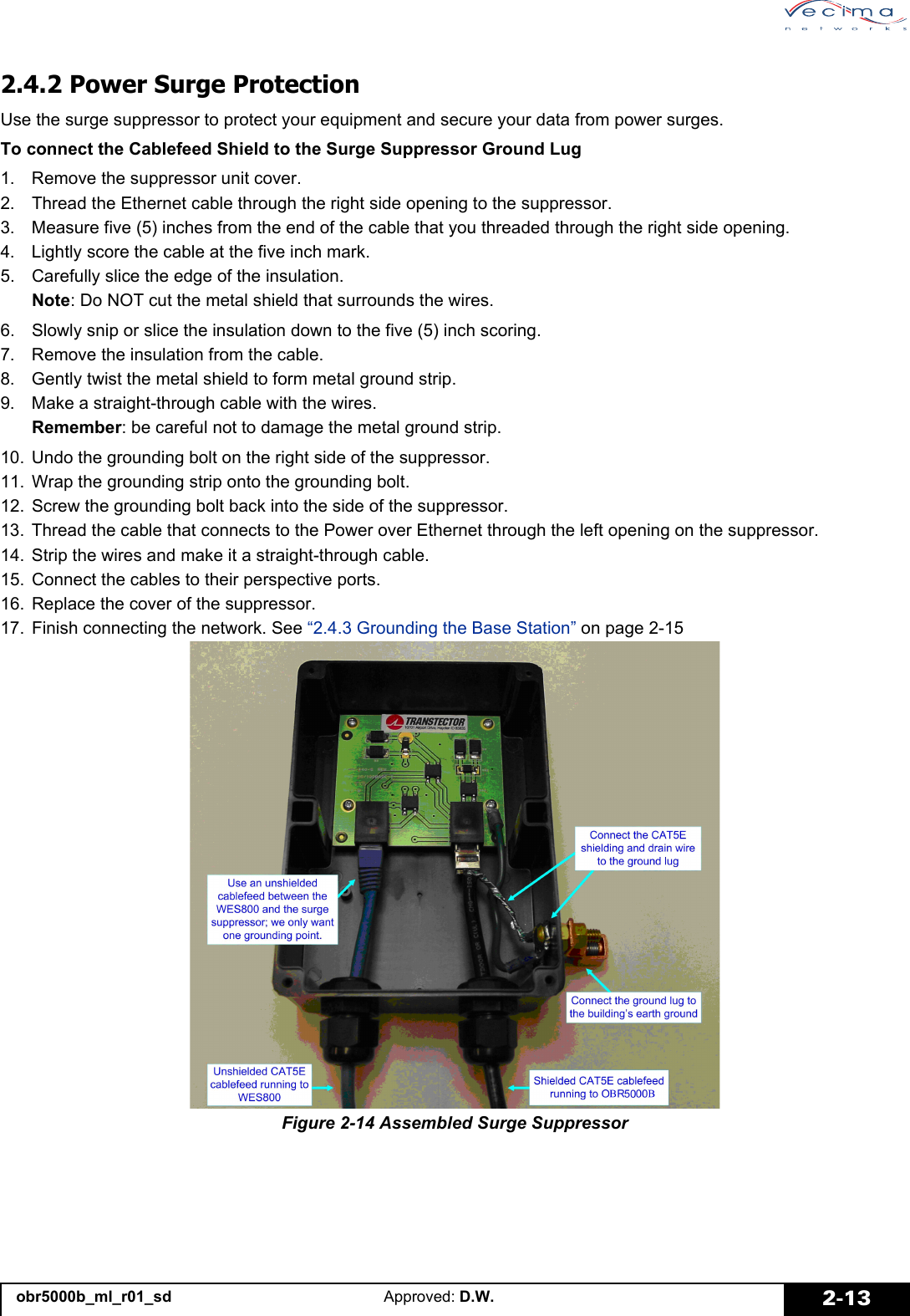
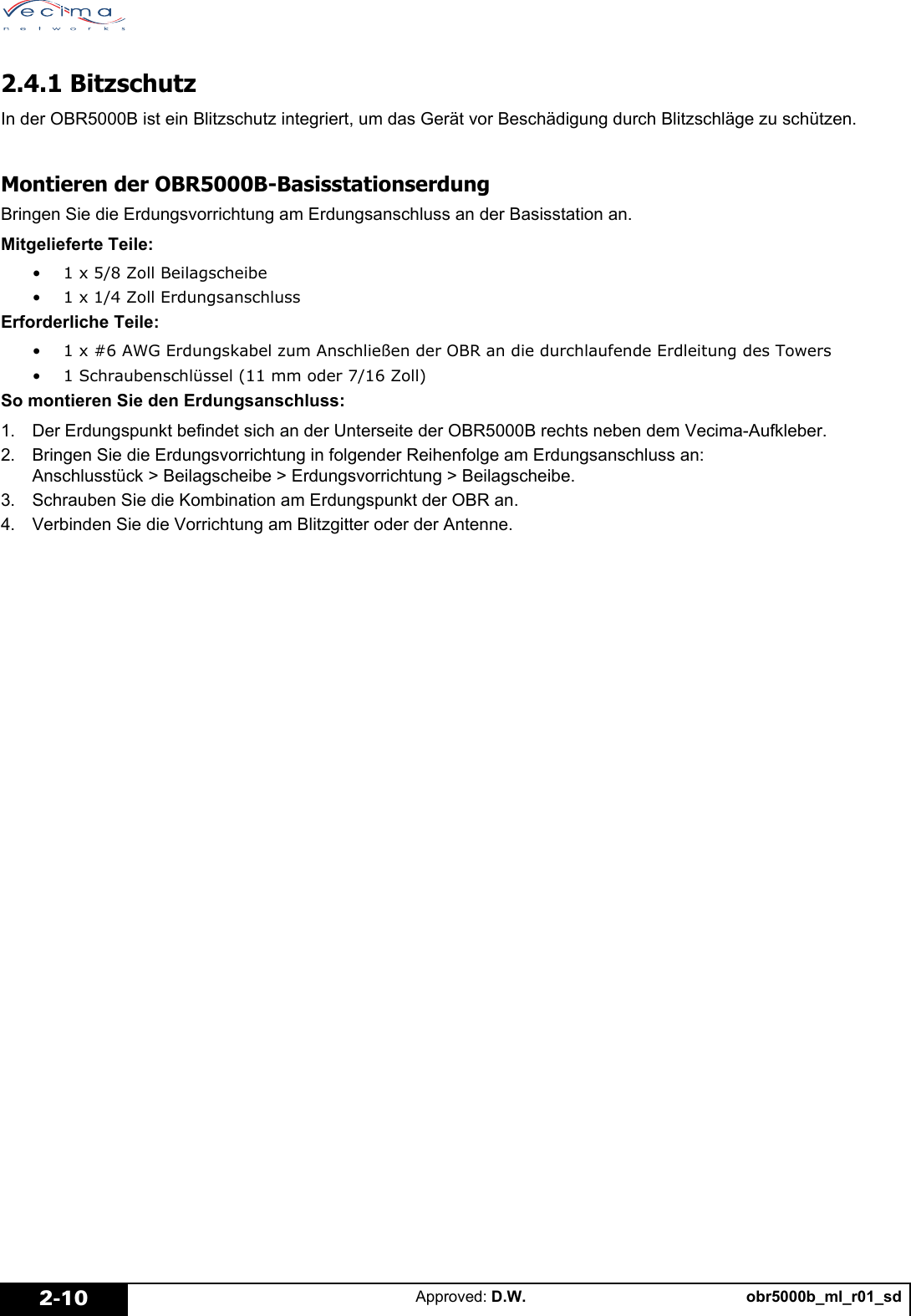
![obr5000b_ml_r01_sd Approved: D.W. 2-92.4 Installing the Grounding ApparatusInstall the grounding apparatus to protect the OBR5000B from lightning strikes and power surges. Ground the base station to the earth ground to protect from lightning strikes. Use the surge suppressor to shunt to ground any over-voltage [>60 V] transients that may be induced on the CAT5E cablefeed via lightning or other high voltages. 2.4 Installieren der ErdungsvorrichtungInstallieren Sie die Erdungsvorrichtung, um die OBR5000B gegen Blitzschlag und Stromstösse zu schützen. Erden Sie die Basisstation für den Schutz gegen Blitzschlag. Verwenden Sie den Überspannungsschutz, um Überspannungen [>60 V] zu überbrücken, die in der CAT5E-Zuleitung durch Blitzschläge oder andere Hochspannungen verursacht werden können.2.4.1 Lightning ProtectionThe OBR5000B has a built in lightning surge suppression mechanism to protect it against damage from lightning strikes.Assembling the OBR5000B Base Station GroundingAttach the earth ground to the grounding lug located on the base station.Provided parts:• 1 x 5/8 inch washer• 1 x 1/4 inch grounding lugRequired parts:• 1 x #6 AWG grounding wire assembly of sufficient length to connect the OBR to the tower’s earth ground bus• 1 Size 11 Wrench (11mm or 7/16 inch)To assemble and attach the ground lug:1. Locate the grounding point on the OBR5000B. This is at the bottom of the OBR, to the right of the Vecima sticker.2. On the grounding lug, assemble the grounding combination in the following order: Lug > Washer > Grounding Assembly > Washer.3. Screw the combination into the OBR at the grounding point.4. Attach the assembly to the lightning grid or the antenna.Figure 2-11 Assembled Ground Lug](https://usermanual.wiki/Vecima-Networks/OBR5000B/User-Guide-1251436-Page-21.png)
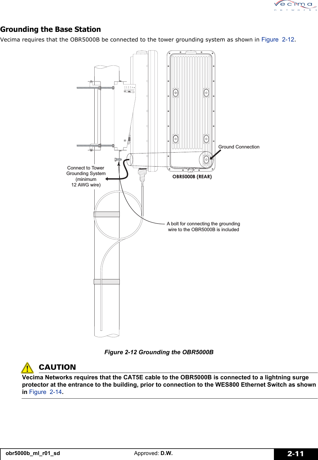
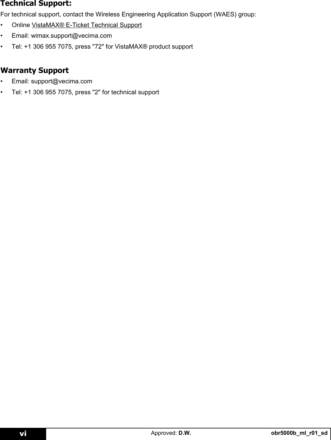
![obr5000b_ml_r01_sdApproved: D.W.2-12Erden der BasisstationDie OBR5000B muss am Towererdungssystem angeschlossen werden (siehe Abbildung 2.9)..Figure 2-13 Abbildung 2.9: Erdung der OBR5000BCAUTIONVorsicht: Eine Anforderung von Vecima Networks besteht darin, dass CAT5E Kabel, die WES800 mit Geräten, die sich im Freien befinden, verbinden an einen Überspannungsschutz angeschlossen werden. Der Anschluss muss am Gebäudeeingang und vor Anschluss an den Transceiver.(LQH6FKUDXEH]XP$QVFKOLHHQGHV(UGXQJVNDEHOVDQGGLH2%5%ZLUGPLWJHOLHIHUW(UGXQJVDQVFKOXVV2%5%5FNVHLWH$QVFKOXVVDP7RZHUHUGXQJVV\VWHPPLQGHVWHQV$:*](https://usermanual.wiki/Vecima-Networks/OBR5000B/User-Guide-1251436-Page-24.png)