Vecima Networks TR707 TR707+700 MHz Subscriber Transceiver User Manual tr707 ml r01 sd
Vecima Networks Inc. TR707+700 MHz Subscriber Transceiver tr707 ml r01 sd
UserManual.wiki
>
Vecima Networks
>
TR707 User Manual
Users Manual
Navigation menu
Upload a User Manual
Namespaces
Wiki Guide
HTML
PDF
Info
Views
User Manual
Discussion / Help
Navigation
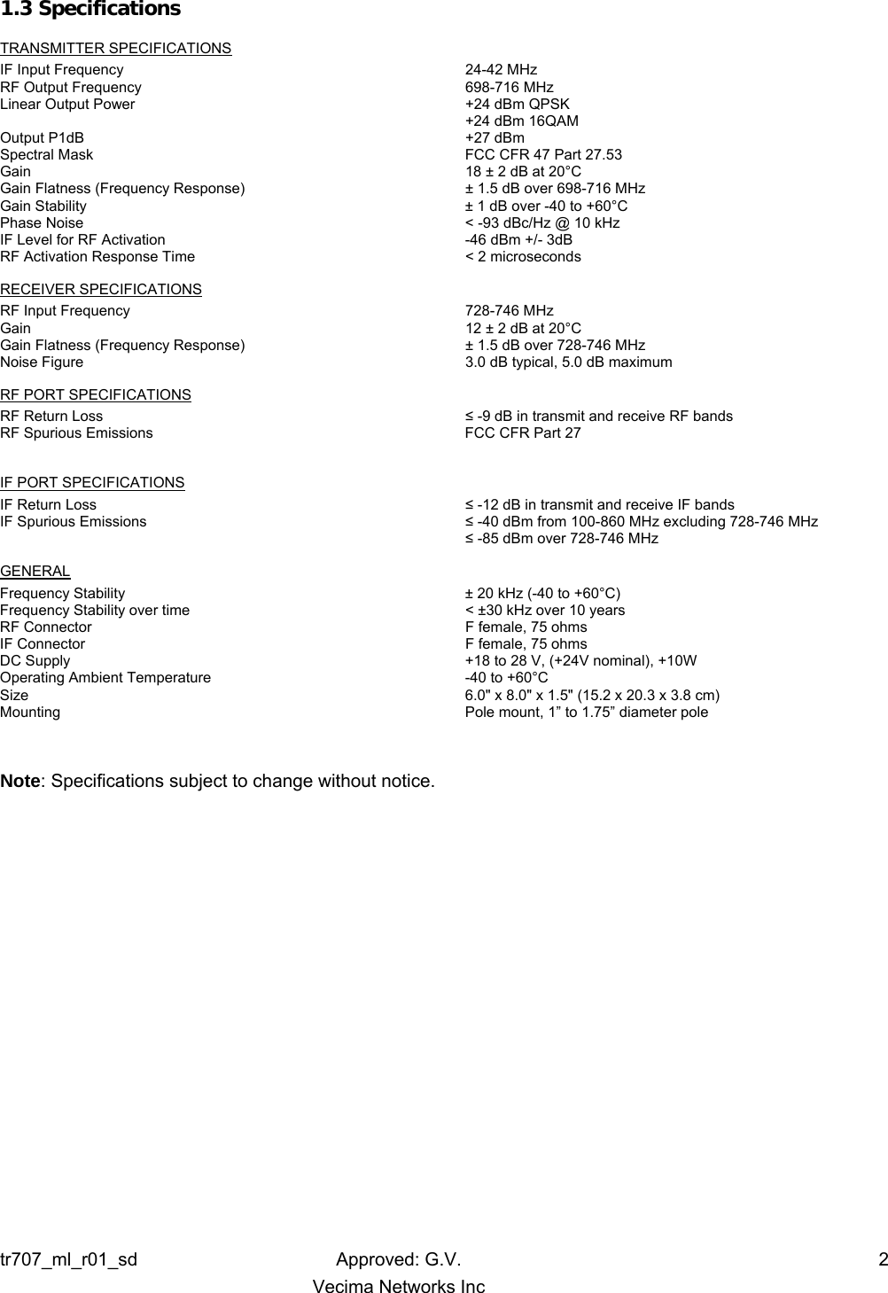
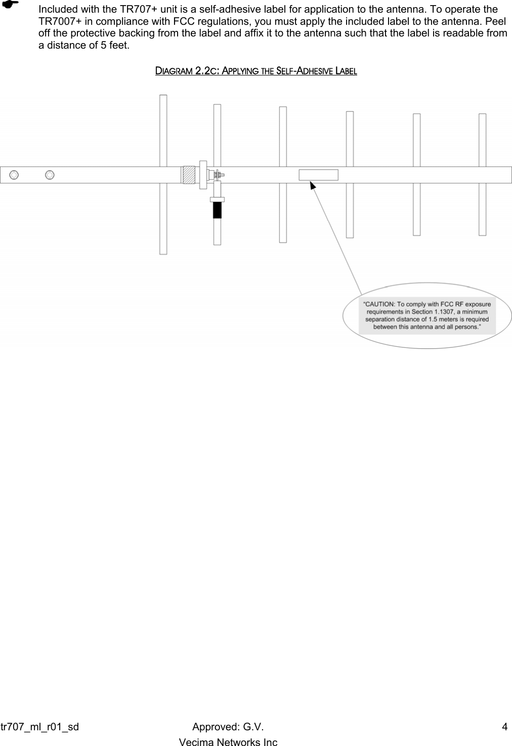
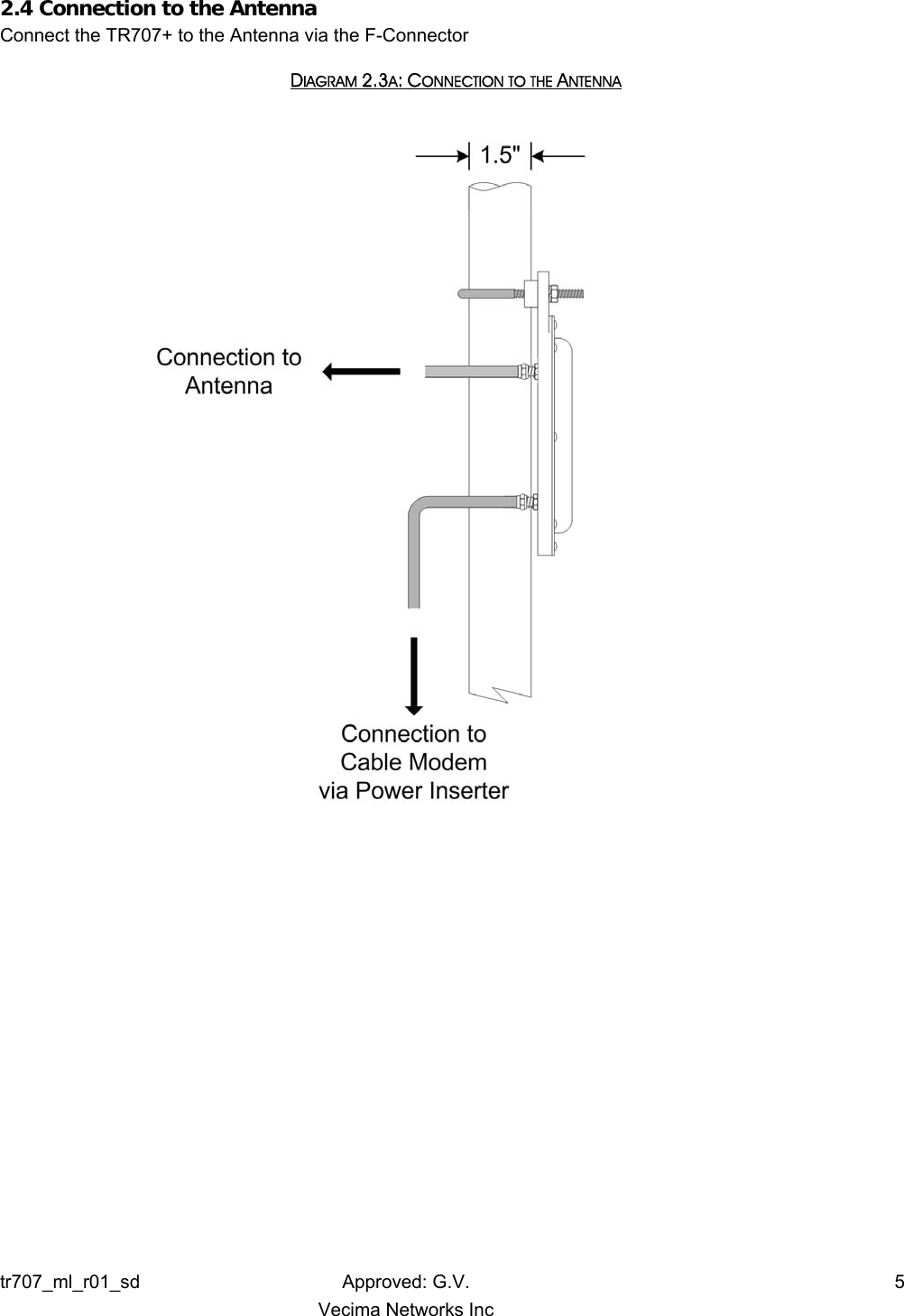
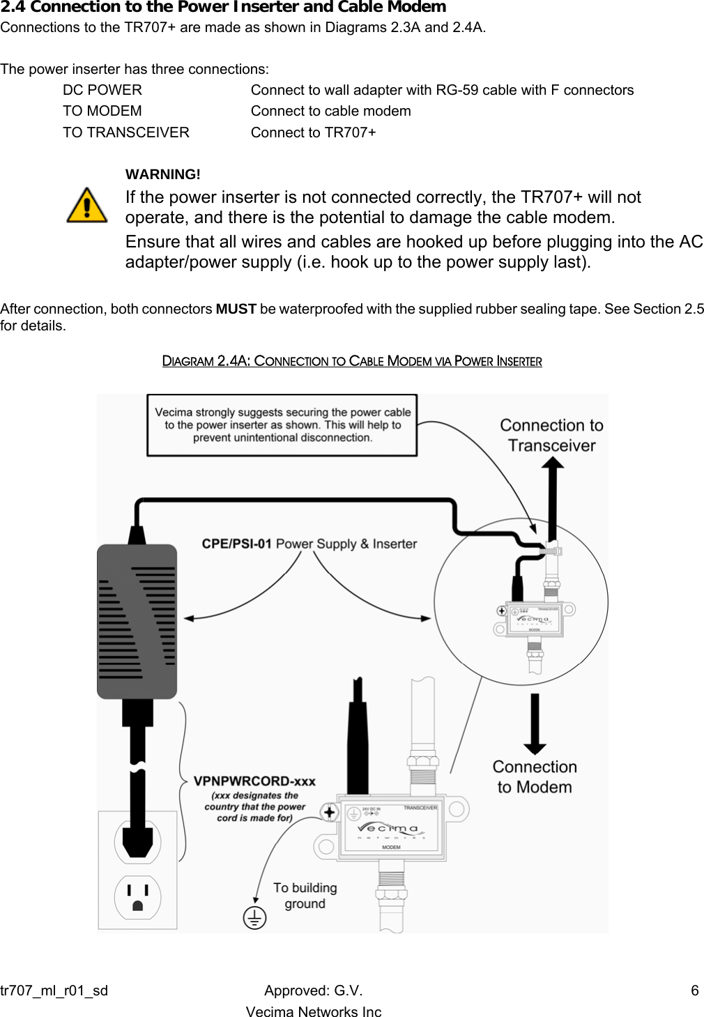
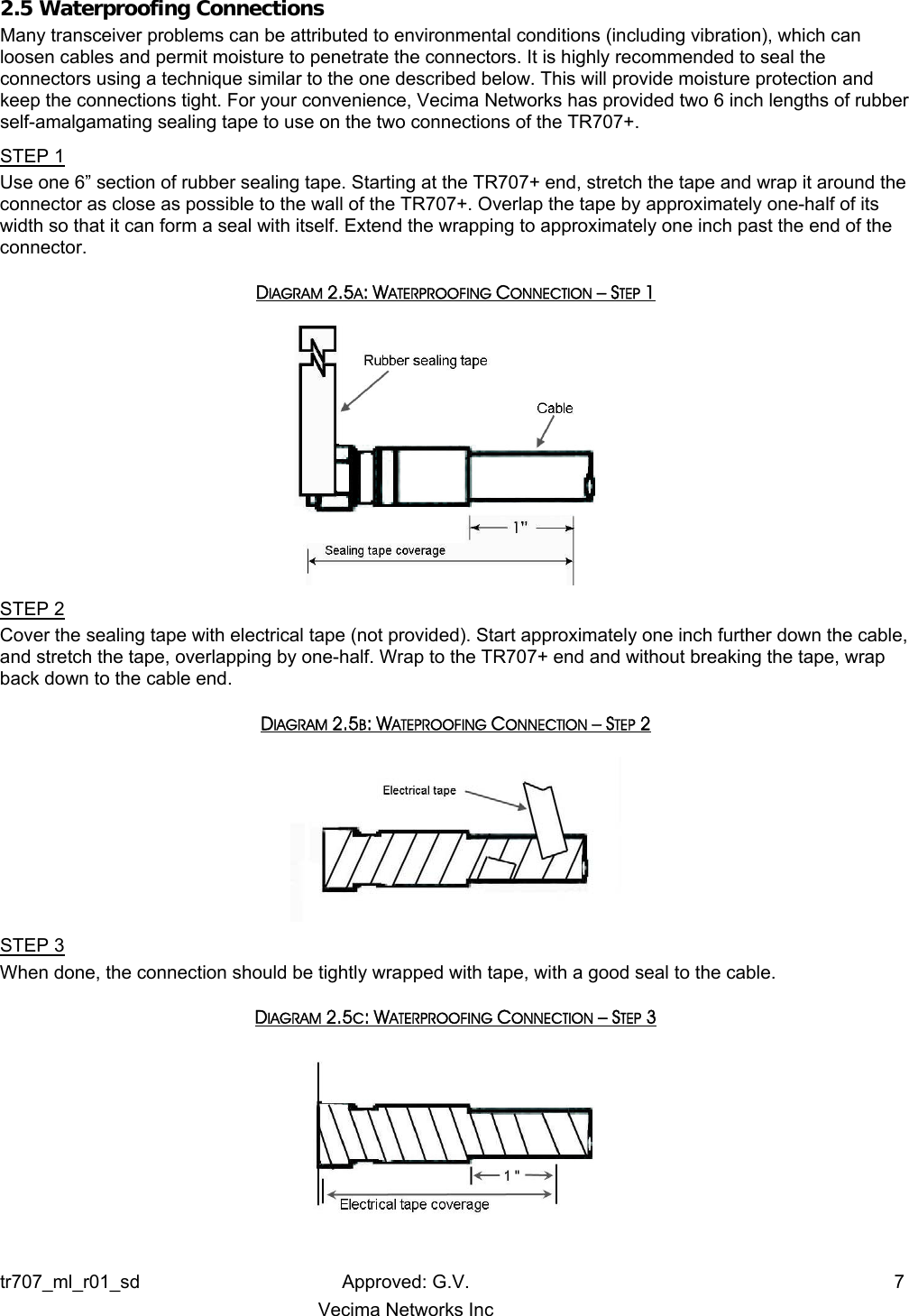
![2.0 INSTALLATION 2.1 Unpacking the Unit Carefully remove the equipment from its packing material and set it on a solid surface, such as a table or desk. If it appears damaged in any way, notify the carrier, and keep all packing materials for inspection by the carrier’s agent. 2.2 Mounting the Unit 2.2.1 Mounting the TR707+ The following hardware is included in the box for mounting the TR707+ to the pole: • One V-bolt to secure the TR707+ to the mounting pole • Two ¼” flange locknuts to secure the V-bolt The TR707+ was designed for mounting to a pole with a diameter of 1.0" to 1.75". Please ensure that the pole used is attached securely to the building or other mounting location. Secure the TR707+ unit to a pole as shown in Figure 2.2A with F-Connector on the bottom. DIAGRAM 2.2A: MOUNTING THE UNIT Top view of TR707+ mounted on pole 2.2.2 Mounting the Antenna Mount the antenna according to the manufacturer’s instructions. ( The TR707+ is intended for use with planar arrays and Yagi antennas. Please consult table 2.2B for further information. TABLE 2.2B: ANTENNA LIST Transceiver Power Antenna Type Antenna Gain [Watts] [dBm] [dBi] 0.25 +24 Yagi 10 dBi 0.25 +24 Flat planar array 9 dBi 0.25 +24 Window mount planar array 7 dBi tr707_ml_r01_sd Approved: G.V. 3 Vecima Networks Inc](https://usermanual.wiki/Vecima-Networks/TR707/User-Guide-1176398-Page-7.png)