Vecima Networks TRI1819 1.9 GHz Braodband Wireless Transceiver User Manual
Vecima Networks Inc. 1.9 GHz Braodband Wireless Transceiver Users Manual
Users Manual
INSTALLATION AND OPERATION GUIDE
FOR SYSTEM OPERATORS

VCom Inc.
TRI1819 Manual; ml_tri1819_02(Feb 2005)
Approved: C.H.
ii
Proprietary to VCom Inc.
All rights reserved.
No part of this publication may be reproduced in any form or by any means or used to make any derivative work (such as translation, transformation or
adaptation) without written permission from VCom Inc.
VCom Inc. reserves the right to revise this publication and to make changes in content from time to time without obligation on the part of VCom Inc. to
provide notification of such revision or change.
VCom Inc. provides this guide without warranty of any kind, either implied or expressed, including, but not limited to, the implied warranties of
merchantability and fitness for a particular purpose. VCom Inc. may make improvements or changes in the product(s) described in this manual at any
time.
TRI1819 Manual; ml_tri1819_02 (Feb 2005); Approved: C.H.
Specifications subject to change without notice — Printed in Canada

VCom Inc.
TRI1819 Manual; ml_tri1819_02(Feb 2005)
Approved: C.H.
iii
Thank-you for purchasing this product
and welcome to VCom!
You have chosen an innovative broadband wireless solution from
a leading technology design center in the ongoing TV & data
delivery revolution.
No doubt you’ve been thinking that the future of your television delivery system includes new technologies such as
Digital TV, Internet Over Cable, Wireless Cable. By selecting VCom, you are benefiting from the same design
powerhouse that since 1988 has created custom RF and digital products for technology leaders such as AT&T,
Cisco Systems, Cogeco, Comcast, and Cox Communications.
VCom designs and manufactures:
Agile CATV Modulators
256 QAM Upconverters
Digital Video Modulators
Frequency Translators
Spread Spectrum Devices
MMDS Transceivers
Off Air/CATV Demodulators
Wireless Cable MMDS
Wireless Cable LMDS
Video On Demand Products
and more! Designs to fill the market needs of the CATV industry – both foreign and domestic.
For additional product or corporate information, contact us:
On the web at: www.vcom.com
By sending email to: sales@vcom.com
By telephone: (306) 955-7075
By fax: (306) 955-9919
By snail mail: VCom Inc.
150 Cardinal Place.
Saskatoon, SK Canada S7L 6H7
VCom's Corporate Mandate
is to be a leading worldwide designer and manufacturer of state-
of-the-art communications equipment and components. Through
the remarkable success of our customers and business partners,
VCom innovations are achieving this goal.

VCom Inc.
TRI1819 Manual; ml_tri1819_02(Feb 2005)
Approved: C.H.
iv
SAFETY PRECAUTIONS
1. Before installing and operating this equipment, read all Safety, Installation and Operating sections. Retain this
manual for future reference.
2. Follow all instructions — Failure to do so may result in damage to the unit or severe personal injury.
3. The user should not attempt servicing. There are no user serviceable parts inside. Refer all servicing to factory
qualified personnel.
4. Shock Hazard — An electrical shock hazard exists when the chassis cover is removed as is required to set
internal controls. Always disconnect power from the unit before removing the cover.
5. Cleaning — Do not use liquid or aerosol cleaners. Use a damp cloth for cleaning.
Warning Do not work on the system or connect or disconnect cables during periods of lightning activity.
LES PRÉCAUTIONS DE SÉCURITÉ
1. Avant d'installer ou d'opérer cet équipement, lisez, toutes les sections de sécurités, d'installations et
d'opérations. Gardez ce manuel comme source de référence.
2. Suivez toutes instructions - si non, vous risquez d'endommager la machine ou de vous blesser sérieusement.
3. N'essayez, pas de réparer cet équipement vous même. Référez toutes revisions nécessaire au personnel
qualifié de la manufacture.
4. Risque de choc - Il y a un risque de décharge électrique qui existe quand la couverture du châssis est enlevée,
comme est nécessaire pour ajuster les contrôles internes. Il faut toujours couper l'électricité avant d'enlever le
couvercle pour faire aucun ajustage.
5. Le nettoyage - n'utilisez pas de nettoyeurs aérosols ou liquides. Utilisez un tissu humide pour nettoyer.
Attention Ne pas travailler sur le système ni brancher ou débrancher les câbles pendant un orage ou du foudre.
CAUTION: To comply with FCC RF exposure requirements in section
1.1307, a minimum separation distance of 1.5 meters is required between
this antenna and all persons.
Important Installation Instructions

VCom Inc.
TRI1819 Manual; ml_tri1819_02(Feb 2005)
Approved: C.H.
v
INDEX
1.0 GENERAL INFORMATION ........................................................................................................................ 6
1.1 Functional Overview..................................................................................................................................................6
1.2 Module Features ........................................................................................................................................................6
1.3 Specifications..............................................................................................................................................................7
2.0 INSTALLATION............................................................................................................................................ 8
2.1 Unpacking the Unit....................................................................................................................................................8
2.2 Mounting the Unit......................................................................................................................................................8
2.3 Connection to the Power Inserter and Cable Modem ..........................................................................................12
2.4 Waterproofing Connections....................................................................................................................................13
3.0 ALIGNING THE ANTENNA...................................................................................................................... 16
3.3.1 Signal Strength and Alignment ...........................................................................................................................16
3.3.2 Resetting the Beeper.............................................................................................................................................16
4.0 WARRANTY AND SERVICE POLICIES.................................................................................................. 17
4.1 Warranty Statement................................................................................................................................................17
4.2 Service Policies: How to Return an Item for Service: ..........................................................................................17
4.3 Repair Charges and Warranty Exemptions..........................................................................................................18

VCom Inc.
TRI1819 Manual; ml_tri1819_02(Feb 2005)
Approved: C.H.
6
1.0 GENERAL INFORMATION
1.1 Functional Overview
The VCom TRI1819 is an outdoor RF transceiver for use in broadband wireless systems. The TRI1819 combines a
low noise downconverter, high power upconverter, antenna and high rejection duplexer to offer a fully integrated
solution for 1.9 GHz subscriber terminals. The TRI1819 integrated subscriber transceiver serves to frequency
translate and amplify the upstream and downstream signals to the appropriate intermediate frequencies for use by
the indoor DOCSIS modem. The TRI1819 and antenna are situated outdoors and connected to a cable modem
indoors by a low cost 75 ohm cable (i.e. RG-59, RG-6 or similar). A single RF F-connector on the weatherproofed
enclosure provides the interface to the transmit/receive antenna for rapid installation.
1.2 Module Features
• Output Power up to +33 dBm EIRP
• Automatic transmit RF mute when modem is not transmitting
• Low Noise: < 6 dB typical
• Digital temperature compensation to guarantee specifications over full operating temperature range
• All local oscillators are frequency synthesized and locked to a common internal high stability reference
• Integrated planar antenna (33° beamwidth, 15 dBi gain)
• High reliability, state-of-the-art design using microstrip, MMIC and surface mount technology
• Conservative component derating and 100% burn in help ensure reliable operation
• Fully weatherized unit, suitable for outdoor mounting
• Audible installation alignment beeper; to facilitate customer self install

VCom Inc.
TRI1819 Manual; ml_tri1819_02(Feb 2005)
Approved: C.H.
7
1.3 Specifications
Subscriber Transceiver Specifications
TRANSMIT SPECIFICATIONS
IF Input Frequency 27 to 42 MHz
Automatic Mute Threshold Level -47 dBm
Automatic Mute Response Time < 2 microseconds
RF Frequency Range 1870 to 1885 MHz (Block B)
Rated Output Power +33 dBm EIRP
Integrated Gain 30 dB ± 1 dB
Gain Stability ±2 dB over temperature (-45 to +55ºC)
Spectral Mask FCC CFR 47 Part 24
Phase Noise <-85 dBc / Hz at 10 kHz
<-45 dBc integrated over 20 kHz to 2.5 MHz
Frequency Setting and Stability ±5.5 kHz
Frequency Stability over 10 years ±15 kHz
RECEIVE SPECIFICATIONS
RF Frequency Range 1950 to 1965 MHz (Block B)
Frequency Response (any 6 MHz band) ±0.5 dB
IF Output Frequency Range 227 to 242 MHz
Noise Figure <6.0 dB typical
Integrated Gain 41 dB
Input Third Order Intercept Point -10 dBm at LNA input
Phase Noise <-85 dBc / Hz at 10 kHz
<-45 dBc integrated over 20 kHz at 2.5 MHz
Frequency Setting and Stability ±5.5 kHz
Frequency Stability over 10 years ±15 kHz
GENERAL
IF Connector F female, 75 ohms
IF Return Losses >10 dB
Power Requirement +10.8 to +28 VDC
Power Consumption 12 W maximum
Operating Temperature Range -45 to +55ºC
Mounting Pole Mount (1” to 1.75” (25mm to 44mm) diameter)
Antenna Gain 15 dBi
Antenna Beamwidth 33° typical
Dimensions 12” x 12” x 3” (305mm x 305mm x 75 mm) maximum
Weight 6 lbs. (2.7 kg)
Specifications subject to change without notice.
VCom Inc.
TRI1819 Manual; ml_tri1819_02(Feb 2005)
Approved: C.H.
8
2.0 INSTALLATION
2.1 Unpacking the Unit
Carefully remove the equipment from its packing material and set it on a solid surface, such as a table or desk. If it
appears damaged in any way, notify the carrier, and keep all packing materials for inspection by the carrier’s agent.
2.2 Mounting the Unit
The following hardware is included in the box for mounting the brackets to the pole:
• 1 L-bracket (taped to one of the foam pieces inside the box)
• 1 pole catch
• 1 V-bolt
• 4 #10-32 flange locknuts for connecting L-bracket to cover
• 2 ¼ - 20 flange locknuts for connecting V-bolt and pole catch to the pole
The TRI1819 was designed for mounting on a pole with a diameter of 1.0” to 1.75”. Please ensure that the pole
used is attached securely to the building or other mounting location.
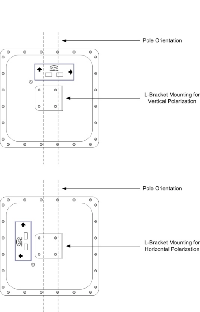
Step 1 – Attach L-Bracket to TRI1819
Before the unit can be attached to the pole, the L-bracket must be attached in the correct orientation according to
the polarization required for the particular customer installation. Diagram 2.2A shows the orientation of the bracket
relative to the cover for both horizontal and vertical polarization.
The active or desired polarization is the one in which the arrow points up. For example, when the TRI1819 is
mounted on the pole, if the arrow pointing up on the back of the TRI1819 says “Horizontal Polarization” then the
horizontal polarization is the active polarization. When the TRI1819 is mounted on the pole, if the arrow pointing up
on the back of the TRI1819 says “Vertical Polarization”, the vertical polarization is the active polarization
Secure the L-bracket to the cover using the #10-32 locknuts.
VCom Inc.
TRI1819 Manual; ml_tri1819_02(Feb 2005)
Approved: C.H.
9
D
DD
DIAGRAM
IAGRAM IAGRAM
IAGRAM 2.2
2.22.2
2.2A
AA
A: L
: L: L
: L-
--
-B
BB
BRACKET
RACKET RACKET
RACKET O
OO
ORIENTATION
RIENTATIONRIENTATION
RIENTATION
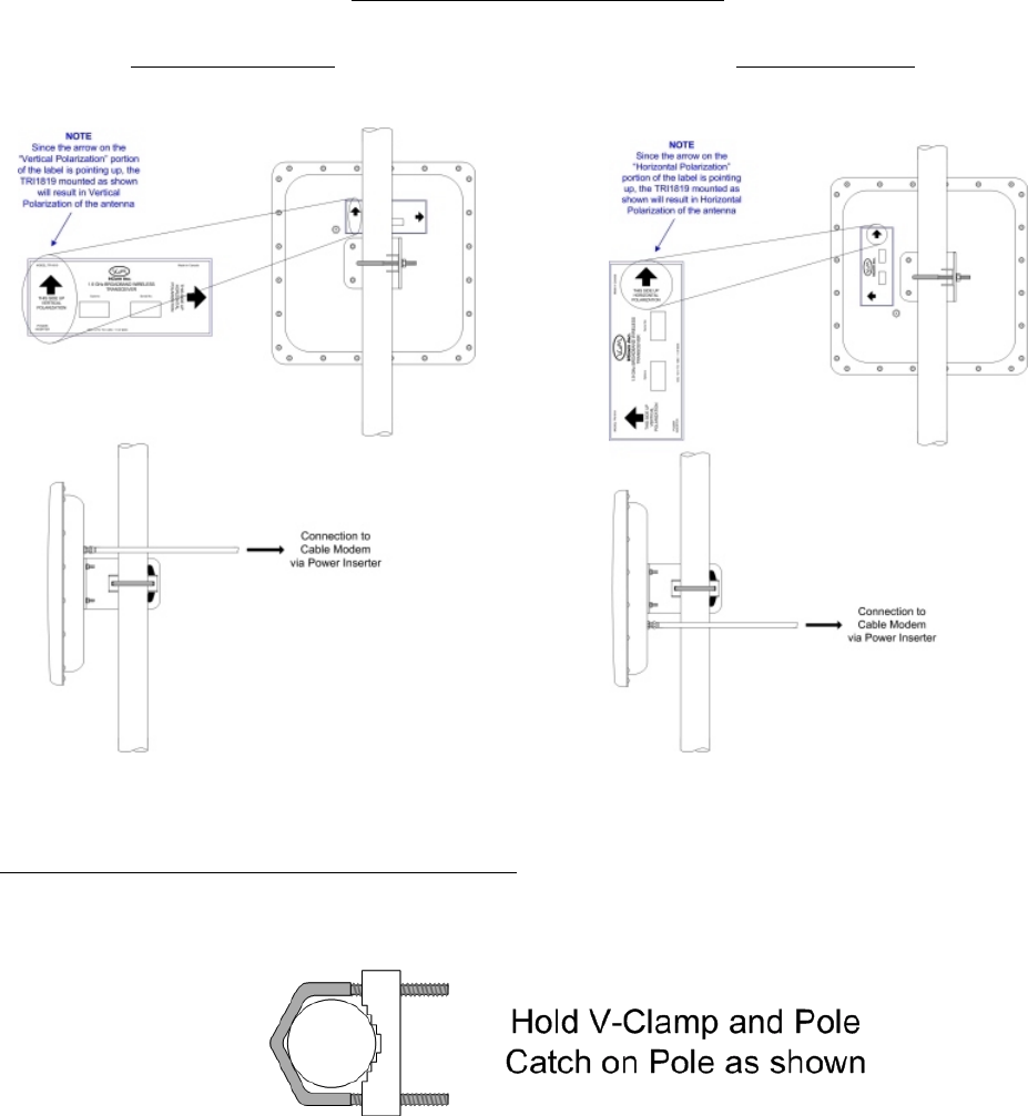
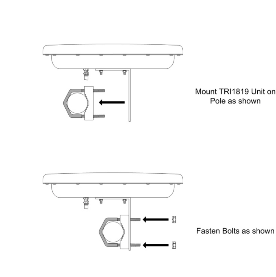
Once the L-bracket is in place, the unit can be mounted to the pole. The pole catch, V-bolt and L-bracket are
oriented as shown in Diagram 2.2B.
VCom Inc.
TRI1819 Manual; ml_tri1819_02(Feb 2005)
Approved: C.H.
10
D
DD
DIAGRAM
IAGRAM IAGRAM
IAGRAM 2.2
2.22.2
2.2B
BB
B: TRI1819 M
: TRI1819 M: TRI1819 M
: TRI1819 MOUNTED TO
OUNTED TO OUNTED TO
OUNTED TO P
PP
POLE
OLEOLE
OLE
Horizontal Alignment Vertical Alignment
STEP 2 – Position V-bolt and pole catch around pole
To attach the TRI1819 to the pole, first position the pole catch over the threads of the V-bolt and hold against the
pole with one hand.
VCom Inc.
TRI1819 Manual; ml_tri1819_02(Feb 2005)
Approved: C.H.
11
STEP 3 – Position TRI1819 against pole
Using the other hand, bring the TRI1819 up to the pole catch and grab V-bolt, pole catch and L-bracket in a single
hand. Ensure that the pole is inside the “L” of the L-bracket and not on the outside of the L. This is necessary to
maintain antenna alignment during high winds.
STEP 4 – Tighten TRI1819 against pole
Tighten both ¼” locknuts against the L-bracket so that the unit is held against the pole but can still be rotated and
tilted up and down for antenna alignment. The locknut closest to the antenna can be tightened almost all the way
while the back one should be approximately finger tight.
VCom Inc.
TRI1819 Manual; ml_tri1819_02(Feb 2005)
Approved: C.H.
12
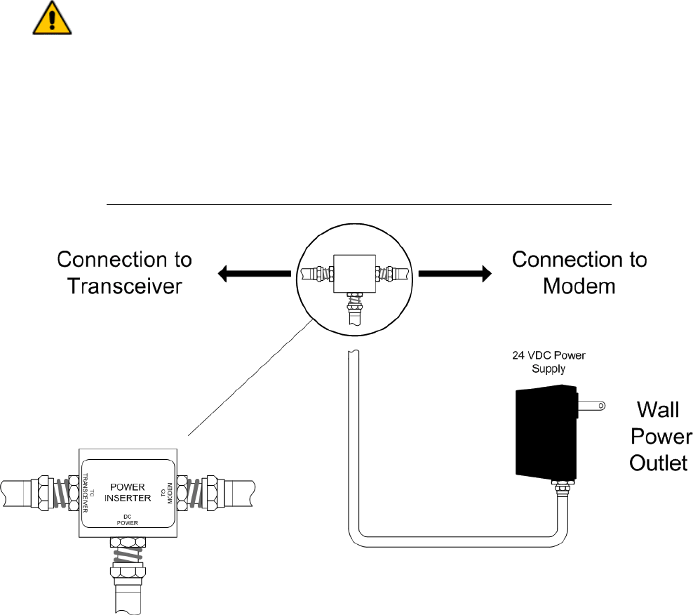
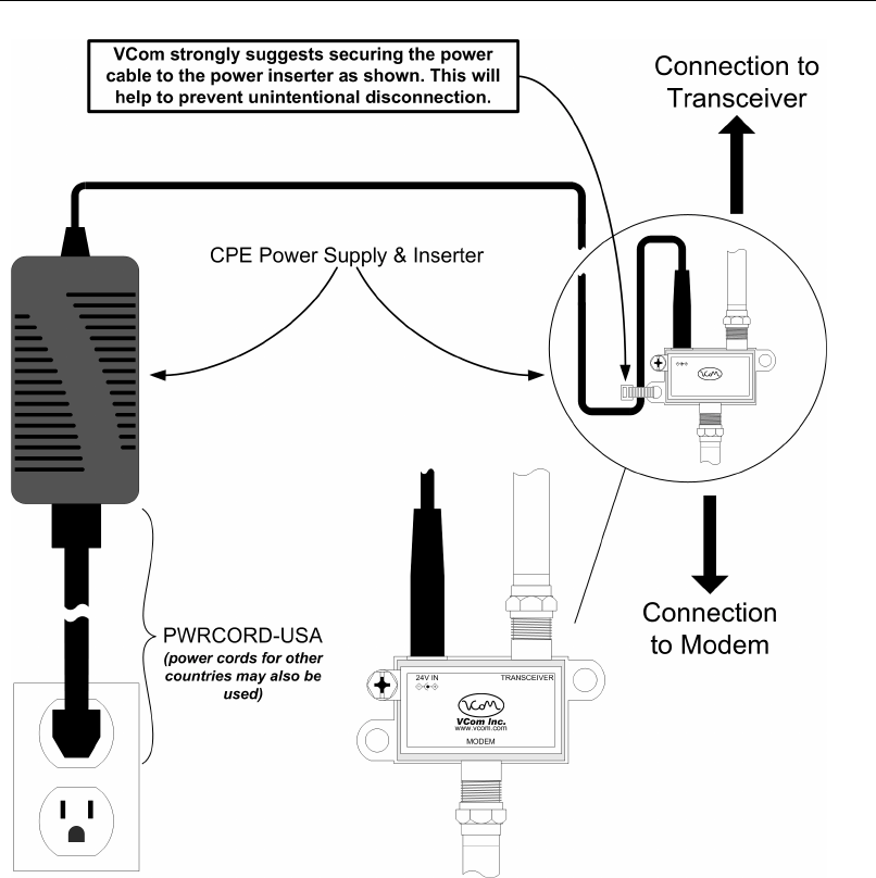
2.3 Connection to the Power Inserter and Cable Modem
Connections to the TRI1819 are made as shown in Diagrams 2.2B and either 2.3A or 2.3B depending on which
power supply and inserter came with the TRI1819.
Please note:
1) Connect the TRI1819 F-Connector to the power inserter, located indoors with the cable modem. The power
inserter is then connected to the Cable Modem, only after the antenna is aligned. The power inserter has
three connections:
DC POWER Connect to wall adapter with the supplied RG-59 cable with F connectors
TO MODEM Connect to cable modem (install modem only after the antenna is aligned)
TO TRANSCEIVER Connect to TRI1819
WARNING!
If the power inserter is not correctly connected, the TRI1819 will not operate, and
there is the potential to damage the cable modem.
Ensure that all wires and cables are hooked up before plugging into the AC
adapter/power supply (i.e. hook up to the power supply last).
2) After connection, the F connector must be waterproofed with the supplied rubber sealing tape. See Section 2.4
for details.
D
DD
DIAGRAM
IAGRAM IAGRAM
IAGRAM 2.3A: C
2.3A: C2.3A: C
2.3A: CONNECTION TO
ONNECTION TO ONNECTION TO
ONNECTION TO C
CC
CABLE
ABLE ABLE
ABLE M
MM
MODEM VIA
ODEM VIA ODEM VIA
ODEM VIA P
PP
POWER
OWER OWER
OWER I
IIINSERTER
NSERTER NSERTER
NSERTER U
UU
USING
SING SING
SING PS24V750MA
PS24V750MAPS24V750MA
PS24V750MA-
--
-01
0101
01
VCom Inc.
TRI1819 Manual; ml_tri1819_02(Feb 2005)
Approved: C.H.
13
D
DD
DIAGRAM
IAGRAM IAGRAM
IAGRAM 2.3B: C
2.3B: C2.3B: C
2.3B: CO
OO
ONNECTION TO
NNECTION TO NNECTION TO
NNECTION TO C
CC
CABLE
ABLE ABLE
ABLE M
MM
MODEM VIA
ODEM VIA ODEM VIA
ODEM VIA P
PP
POWER
OWER OWER
OWER I
IIINSERTER
NSERTER NSERTER
NSERTER U
UU
USING
SING SING
SING CPE P
CPE PCPE P
CPE POWER
OWER OWER
OWER S
SS
SUPPLY
UPPLY UPPLY
UPPLY & I
& I& I
& INSERTER
NSERTERNSERTER
NSERTER
VCom Inc.
TRI1819 Manual; ml_tri1819_02(Feb 2005)
Approved: C.H.
14
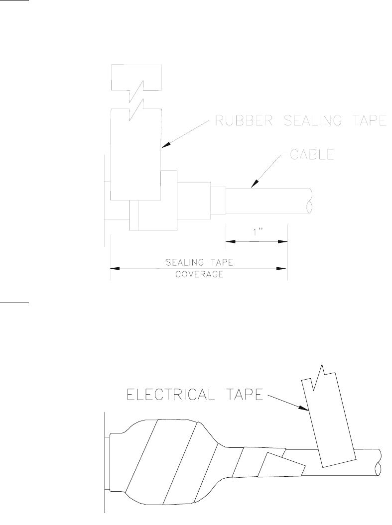
2.4 Waterproofing Connections
This will provide moisture protection and keep the connections tight. VCom has provided a 6-inch length of rubber
self-amalgamating sealing tape to use on the TRI1819 F-connector.
Step 1
Use a 6” section of rubber sealing tape. Starting at the TRI1819 end, stretch the tape and wrap it around the
connector as close as possible to the wall of the TRI1819. Overlap the tape by approximately one-half of its width
so that it can form a seal with itself. Extend the wrapping to approximately one-inch past the end of the connector.
Step 2
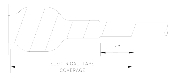
Cover the sealing tape with electrical tape (not provided). Start approximately one inch further down the cable, and
stretch the tape, overlapping by one-half. Wrap to the TRI1819 end and without breaking the tape, wrap back down
to the cable end.
VCom Inc.
TRI1819 Manual; ml_tri1819_02(Feb 2005)
Approved: C.H.
15
When done, the connection should be tightly wrapped with tape, with a good seal to the cable.

VCom Inc.
TRI1819 Manual; ml_tri1819_02(Feb 2005)
Approved: C.H.
16
3.0 ALIGNING THE ANTENNA
3.3.1 Signal Strength and Alignment
When power is first applied an audible signal (beep) will occur. Faster beeping indicates higher signal strength.
Adjust the unit first panning left and right, then up and down until the rate of beeping is maximized. If the unit is
difficult to tilt or turn, loosen the locknuts on the V-bolts slightly.
If the beep rate is very quick, the beeps will continue to be heard for ~3mins and then stop. This quick beep rate
indicates that very little movement is necessary. If the beep rate is slow, the beep will occur for 20 minutes at
minimum signal strength of less than –80 dBm. This slow beep rate indicates that more movement is required.
Once antenna alignment is complete, tighten the locknuts to secure the TRI1819 to the pole.
3.3.2 Resetting the Beeper
To reset the timer for alignment, simply unplug the power supply from its AC connection. Wait 5 seconds, then plug
the power supply back into its AC connection. The beeper will begin beeping as soon as power is available.

VCom Inc.
TRI1819 Manual; ml_tri1819_02(Feb 2005)
Approved: C.H.
17
4.0 WARRANTY AND SERVICE POLICIES
4.1 Warranty Statement
VCom warrants its products to be free from defects in workmanship or materials for a period of two years. The
warranty begins on the date of the original shipment from VCom to its customer. No claim may be allowed for
expenses incurred in installation or use. No other expressed or implied warranties shall apply to the goods sold.
VCom is not responsible for delayed shipments, other loss beyond VCom’s control, or consequential damages of
any kind arising in connection with the use of its products. This warranty is a return-to-factory warranty only.
During the warranty period VCom will at its option, replace, repair or refund the price paid for any item which is
returned for service. This warranty does not apply to units that have been physically or environmentally abused.
4.2 Service Policies: How to Return an Item for Service:
Before returning any item for service, an R.M.A. (Returned Material Authorization) number must be assigned by
VCom. A unique R.M.A. number will be assigned for each item being returned. When requesting an R.M.A.
number, please be prepared to provide the model, VCom serial number, original invoice number, your purchase
order number and an adequate fault description. The serial number of a unit can be found on a barcode label
similar to the one pictured below. R.M.A. service is available Monday to Friday from 8:30 a.m. to 4:30 p.m. CST
(statutory holidays excepted).
To obtain an R.M.A. number you may:
Call: (306) 955-7075, press ‘0’ for Operator, or ‘3’ for Service Dept.
Fax: (306) 384-0086 — Attention: R.M.A. Request
Email: support@vcom.com
Once an R.M.A. number has been assigned, please refer to it in all correspondence and make certain that all
applicable R.M.A. numbers are clearly marked on the outside of each package being returned. You must also
ensure that each product is shipped to VCom in its original shipping container (or equivalent) via Prepaid carrier,
with appropriate insurance and customs documentation (where required). VCom will not accept collect shipments,
damaged shipments or shipments unaccompanied by an R.M.A. number.
For items still under Warranty – Items will be returned from VCom Inc. to its customer via prepaid ground carrier.
The customer is responsible for any additional costs incurred, including custom clearance and duties. Any
alternate means of shipment must be requested by the customer and will be subject to additional charges.
For items no longer under Warranty – Items will be returned from VCom Inc. to its customer via prepaid ground
carrier at the customer’s expense. The customer is responsible for any additional costs incurred, including custom
clearance and duties. Any alternate means of shipment must be requested by the customer and will be subject to
additional charges.
Shipping Instructions will be provided by the repair center when the RMA number is sent to the customer.
VCom Inc.
TRI1819 Manual; ml_tri1819_02(Feb 2005)
Approved: C.H.
18
4.3 Repair Charges and Warranty Exemptions
Items returned beyond the warranty period or items that do not qualify for warranty service are subject to additional
out-of-warranty repair charges. Descriptions of these charges and warranty exemptions are below:
1) Repair turnaround time is typically 5-14 business days after receipt of the item at VCom. A Flat Rate Repair Charge
will apply to all out-of-warranty items. Flat Rate Repair Charges are subject to change without notice.
2) Any faults due to customer error (i.e. - incorrect set-up or configuration settings) are subject to the current
Test Fee and will be exempt from warranty.
3) Items returned with inadequate fault descriptions are subject to the current Test Fee and are
exempt from warranty.
4) In the event that no fault is found, the item is subject to the current Test Fee and will be
exempt from warranty.
5) Any product exhibiting external damage (either from shipping, improper handling or use) will be subject to inspection.
If said damages are determined to be the cause of failure, the item will be exempt from warranty.
All repairs to correct the external damage are subject to Time & Materials Charges (parts and labor at current rates).
6) Items with damage caused by unauthorized repairs or by external devices are subject to current out-of-warranty
Flat Rate Repair Charges and are exempt from warranty.
7) All products returned for Factory Optioning are subject to the applicable current Option Charge plus Test Fee.
Factory-optioned products carry the balance of the original warranty or a 90 day warranty, whichever is greater.
All out-of-warranty repairs must be approved by the customer in writing. No repairs will be made until the customer’s
Purchase Order or Out-Of-Warranty Repair Authorization is received.


150 Cardinal Place
Saskatoon, Saskatchewan
S7L 6H7
Canada
Tel: (306) 955-7075
Fax: (306) 955-9919
www.vcom.com
sales@vcom.com