Vecima Networks TRI5758 TRI5758 Integrated Broadband Wireless Transceiver User Manual
Vecima Networks Inc. TRI5758 Integrated Broadband Wireless Transceiver
User manual
5.7-5.8 GHz Integrated
Broadband Wireless
Transceiver
TRI5758
INSTALLATION AND OPERATION GUIDE
FOR SYSTEM OPERATORS
WaveCom Electronics Inc
TRI5758 Manual; ML_TRI5758_03 (June 2003)
Approval Pending
ii
Thank-you for purchasing this
product and welcome to WaveCom!
You have chosen an innovative broadband wireless
solution from a leading technology design center in the
ongoing TV & data delivery revolution.
No doubt you’ve been thinking that the future of your television delivery system includes new technologies such as
Digital TV, Internet Over Cable, Wireless Cable. By selecting WaveCom, you are benefiting from the same
design powerhouse that since 1988 has created custom RF and digital products for technology leaders such as
AT&T, Cisco Systems, Cogeco, Comcast, and Cox Communications.
WaveCom designs and manufactures:
✔
✔✔
✔Agile CATV Modulators ✔
✔✔
✔256 QAM Upconverters ✔
✔✔
✔Digital Video Modulators
✔
✔✔
✔Frequency Translators ✔
✔✔
✔Spread Spectrum Devices ✔
✔✔
✔Off-Air Demodulators
✔
✔✔
✔Video-On-Demand Products ✔
✔✔
✔Wireless Cable MMDS ✔
✔✔
✔Wireless Cable LMDS
✔
✔✔
✔Frequency Stackers ✔
✔✔
✔Subscriber Transceivers ✔
✔✔
✔Satellite Receivers
and more! Designs to fill the market needs of the CATV industry – both foreign and domestic.
For additional product or corporate information, contact us:
On the web at: www.WaveCom.ca
By sending email to: sales@WaveCom.ca
By telephone: (306) 955-7075
By fax: (306) 955-9919
By snail mail: WaveCom Electronics Inc.
150 Cardinal Place.
Saskatoon, SK Canada S7L 6H7
WaveCom's Corporate Mandate
is to be a leading worldwide designer and manufacturer of state-
of-the-art communications equipment and c
omponents. Through
the remarkable success of our customers and business partners,
WaveCom innovations are achieving this goal.

WaveCom Electronics Inc
TRI5758 Manual; ML_TRI5758_03 (June 2003)
Approval Pending
iii
Proprietary to WaveCom Electronics Inc.
All rights reserved.
No part of this publication may be reproduced in any form or by any means or used to make any derivative work (such as translation, transformation or
adaptation) without written permission from WaveCom Electronics Inc.
WaveCom Electronics Inc. reserves the right to revise this publication and to make changes in content from time to time without obligation on the part of
WaveCom Electronics Inc. to provide notification of such revision or change.
WaveCom Electronics Inc. provides this guide without warranty of any kind, either implied or expressed, including, but not limited to, the implied warranties
of merchantability and fitness for a particular purpose. WaveCom Electronics Inc. may make improvements or changes in the product(s) described in
this manual at any time.
TRI5758 Manual; ML_TRI5758_02 (May 2003); Approval Pending
Specifications subject to change without notice — Printed in Canada

WaveCom Electronics Inc
TRI5758 Manual; ML_TRI5758_03 (June 2003)
Approval Pending
iv
SAFETY PRECAUTIONS
1. Before installing and operating this equipment, read all Safety, Installation and Operating sections. Retain this
manual for future reference.
2. Follow all instructions — Failure to do so may result in damage to the unit or severe personal injury.
3. The user should not attempt servicing. There are no user serviceable parts inside. Refer all servicing to factory
qualified personnel.
4. Cleaning — Do not use liquid or aerosol cleaners. Use a damp cloth for cleaning.
Warning
Do not work on the system or connect or disconnect cables during periods of lightning activity.
LES PRÉCAUTIONS DE SÉCURITÉ
1. Avant d'installer ou d'opérer cet équipement, lisez, toutes les sections de sécurités, d'installations et
d'opérations. Gardez ce manuel comme source de référence.
2. Suivez toutes instructions - si non, vous risquez d'endommager la machine ou de vous blesser sérieusement.
3. N'essayez, pas de réparer cet équipement vous même. Référez toutes revisions nécessaire au personnel
qualifié de la manufacture.
4. Le nettoyage - n'utilisez pas de nettoyeurs aérosols ou liquides. Utilisez un tissu humide pour nettoyer.
Attention
Ne pas travailler sur le système ni brancher ou débrancher les câbles pendant un orage du foudre.

WaveCom Electronics Inc
TRI5758 Manual; ML_TRI5758_03 (June 2003)
Approval Pending
v
INFORMATION TO USER
This device complies with Part 15 of the FCC Rules. Operation is subject to the following two conditions: (1) This
device may not cause harmful interference, and (2) This device must accept any interference received, including
interference that may cause undesired operation.
This equipment has been tested and found to comply with the limits for Class B Digital Device, pursuant to Part 15 of
the FCC Rules. These limits are designed to provide reasonable protection against harmful interference in a
residential installation. This equipment generates and can radiate radio frequency energy and, if not installed and used
in accordance with the instructions, may cause harmful interference to radio communications. However, there is no
guarantee that interference will not occur in a particular installation. If this equipment does cause harmful interference
to radio or television reception, which can be determined by turning the equipment off and on, the user is encouraged
to try to correct the interference by one or more of the following measures:
• Reorient or relocate the receiving antenna
• Increase the separation between the equipment and receiver
• Connect the equipment into an outlet on a circuit different from that to which the receiver is connected
• Consult the dealer or an experienced radio/TV technician for help
CAUTION: Any changes or modifications not expressly approved by WaveCom Electronics, Inc. could void the user’s
authority to operate the equipment.
CAUTION: This device must be professionally installed.
WARNING:
In order to comply with the FCC radiofrequency exposure limits of 1.1310, this equipment must be installed in such
a way as to provide a minimum separation distance of 0.5m from the transmitting antenna to persons nearby.
The installer of this radio equipment must ensure that the antenna is located or pointed such that it does not emit
RF fields in excess of Health Canada’s limits for the general population; consult Safety Code 6, obtainable from
Health Canada’s Website www.hc-sc.gc.ca/rpb.

WaveCom Electronics Inc
TRI5758 Manual; ML_TRI5758_03 (June 2003)
Approval Pending
vi
INDEX
1.0 GENERAL INFORMATION.........................................................................................................................7
1.1 Functional Overview...............................................................................................................................................7
1.2 Module Features......................................................................................................................................................7
1.3 Specifications ...........................................................................................................................................................8
2.0 INSTALLATION ............................................................................................................................................9
2.1 Unpacking the Unit .................................................................................................................................................9
2.2 Mounting the Unit...................................................................................................................................................9
2.3 Connection to the Power Inserter and Cable Modem ........................................................................................14
2.4 Waterproofing Connections .................................................................................................................................15
3.0 TUNING THE ANTENNA...........................................................................................................................17
3.1 Signal Strength Tuning via Internal Beeper. ......................................................................................................17
3.2 Reset the Unit to continue Tuning........................................................................................................................17
4.0 WARRANTY AND SERVICE POLICIES...................................................................................................18
4.1 Warranty Statement..............................................................................................................................................18
4.2 Service Policies: How to Return an Item for Service:.........................................................................................18
4.3 Repair Charges and Warranty Exemptions........................................................................................................19

WaveCom Electronics Inc
TRI5758 Manual; ML_TRI5758_03 (June 2003)
Approval Pending
7
WaveCom’s TRI5758 is an all-weather transceiver designed for subscriber end-use in a fixed broadband wireless
system. The TRI5758 combines a low noise downconverter, high power upconverter, directional antenna, and high
rejection diplexer to offer a fully integrated RF solution. The TRI5758 transceiver serves to frequency translate and
amplify both Upstream and Downstream signals to the appropriate intermediate frequencies for use by an indoor a
DOCSIS-compliant or similar cable modem. The TRI5758 is intended to be installed outdoors and connected to the
cable modem via low cost 75-ohm coaxial cable such as RG-59, or RG-6. The weatherproof enclosure includes an
external F-connector, and internal signal strength indicating beeper, which allows for easy alignment and
installation of the unit.
• Meets unlicensed-band maximum allowable transmit power of +28 dBm EIRP
• High Receive Gain of 53 dB allows for optimal Downstream signal recovery for high SNR
• Automatic transmitter RF mute when modem is not transmitting
• Low Noise Figure; < 6 dB typical
• Digital temperature compensation to guarantee specifications over full operating range
• All local oscillators are frequency synthesized and locked to a common internal high stability reference
• Integrated planar antenna
• High reliability, state-of-the-art design using microstrip, MMIC and surface mount technology
• Conservative component derating and 100% burn in help ensure reliable operation
• Fully weatherized unit, suited for outdoor mounting
• Audible installation alignment beeper; to facilitate customer self install
WaveCom Electronics Inc
TRI5758 Manual; ML_TRI5758_03 (June 2003)
Approval Pending
8
TRANSMIT SPECIFICATIONS
IF Input Frequency 18 to 42 MHz
RF Output Frequency 5727 - 5751 MHz (Option T5727-5751R5775-5799)
5751 - 5775 MHz (Option T5751-5775R5799-5823)
Gain (Integrated) 26 dB +/- 2 dB
Gain Flatness (Frequency Response) +/- 1 dB full band
+/- 0.5 dB over any 6 MHz band
Gain Stability over Temperature +/- 2.0 dB
Linear Output Power +5 dBm into antenna (16 QAM, QPSK)
Spurious (at transmit port) -40 dBm 9 kHz to 21.4 GHz
Phase Noise < -85 dBc/Hz @ 10 KHz typical
Spectral Inversion No spectral inversion
Return Loss (IF) 10 dB in Transmit and Receive bands
IF Level for RF Activation + 5 dBmV
RF Activation/Mute Response Time <2 microseconds
DOWNCONVERTER SPECIFICATIONS
RF Input Frequency 5775 - 5799 MHz (Option T5727-5751R5775-5799)
5799 - 5823 MHz (Option T5751-5775R5799-5823)
IF Output Frequency 516 -540 MHz
Gain (Integrated) 53 dB +/- 2 dB
Gain Flatness (Frequency Response) +/- 1.5 dB full band
+/- 0.5 dB any 6 MHz band
Gain Stability over Temperature +/- 2.0 dB
Noise Figure 6.0 dB typical, 7dB max
Image Rejection 90 dB minimum
Discrete Spurious (at IF port) -80 dBm between 510 and 546 MHz
-50 dBm from 5 MHz to 510 MHz and from 546 MHz to 860 MHz
Phase Noise (IF) <-85 dBc/Hz @ 10 kHz typical
Spectral Inversion No spectral inversion
GENERAL
Integrated Flat Panel Antenna
Gain 23 dBi
Beamwidth 9.0 degrees
Polarity Vertical or Horizontal
Cross Polarization Isolation 20 dB
Front/Back Ratio 30 dB
Frequency Setting & Stability +/- 15 kHz (-30 to +40°C)
Frequency Stability Over Time < +/- 25 kHz over 10 years
IF Connector F female, 75 ohms
DC Supply 18 to 24 VDC, 12W max.
Operating Temperature -30°C to +40°C (full specifications)
-45°C to +45°C (operational)
Size 30.5 x 30.5 x 7.5 cm (12" x 12" x 3")
Mounting Pole mount
1" to 2.5" dia. pole or wall mount with 90 deg pol, az and el adjustment
Weight 2.7kg max.
WaveCom Electronics Inc
TRI5758 Manual; ML_TRI5758_03 (June 2003)
Approval Pending
9
Carefully remove the equipment from its packing material and set it on a solid surface, such as a table or desk. If it
appears damaged in any way, notify the carrier, and keep all packing materials for inspection by the carrier’s
agent.
The following hardware is included in the box for mounting the brackets to the pole:
• 1 L-bracket (taped to one of the foam pieces inside the box)
• 1 pole catch
• 1 V-bolt
• 4 #10-32 flange locknuts for connecting L-bracket to cover
• 2 ¼ - 20 flange locknuts for connecting V-bolt and pole catch to the pole
The TRI5758 was designed for mounting on a pole with a diameter of 1.0” to 1.75”. Please ensure that the pole
used is attached securely to the building or other mounting location.
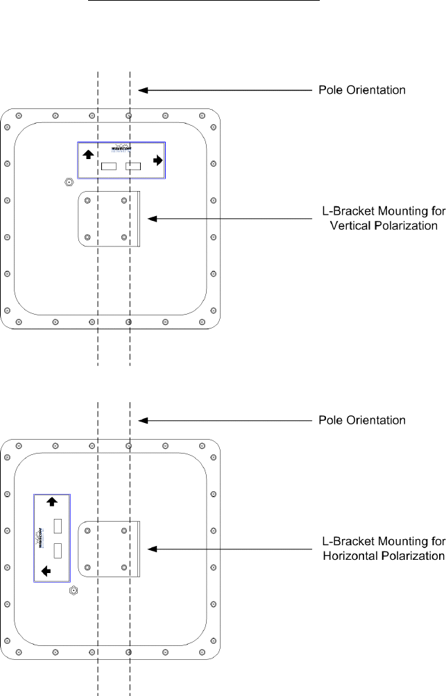
Step 1 – Attach L-Bracket to TRI5758
Before the unit can be attached to the pole, the L-bracket must be attached in the correct orientation according to
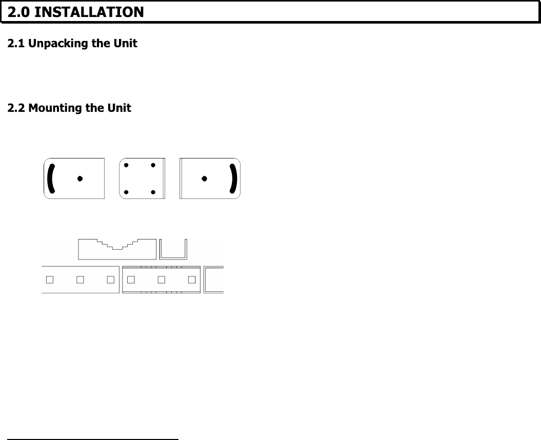
the polarization required for the particular customer installation. Diagram 2.2A shows the orientation of the bracket
relative to the cover for both horizontal and vertical polarization.
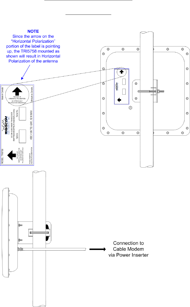
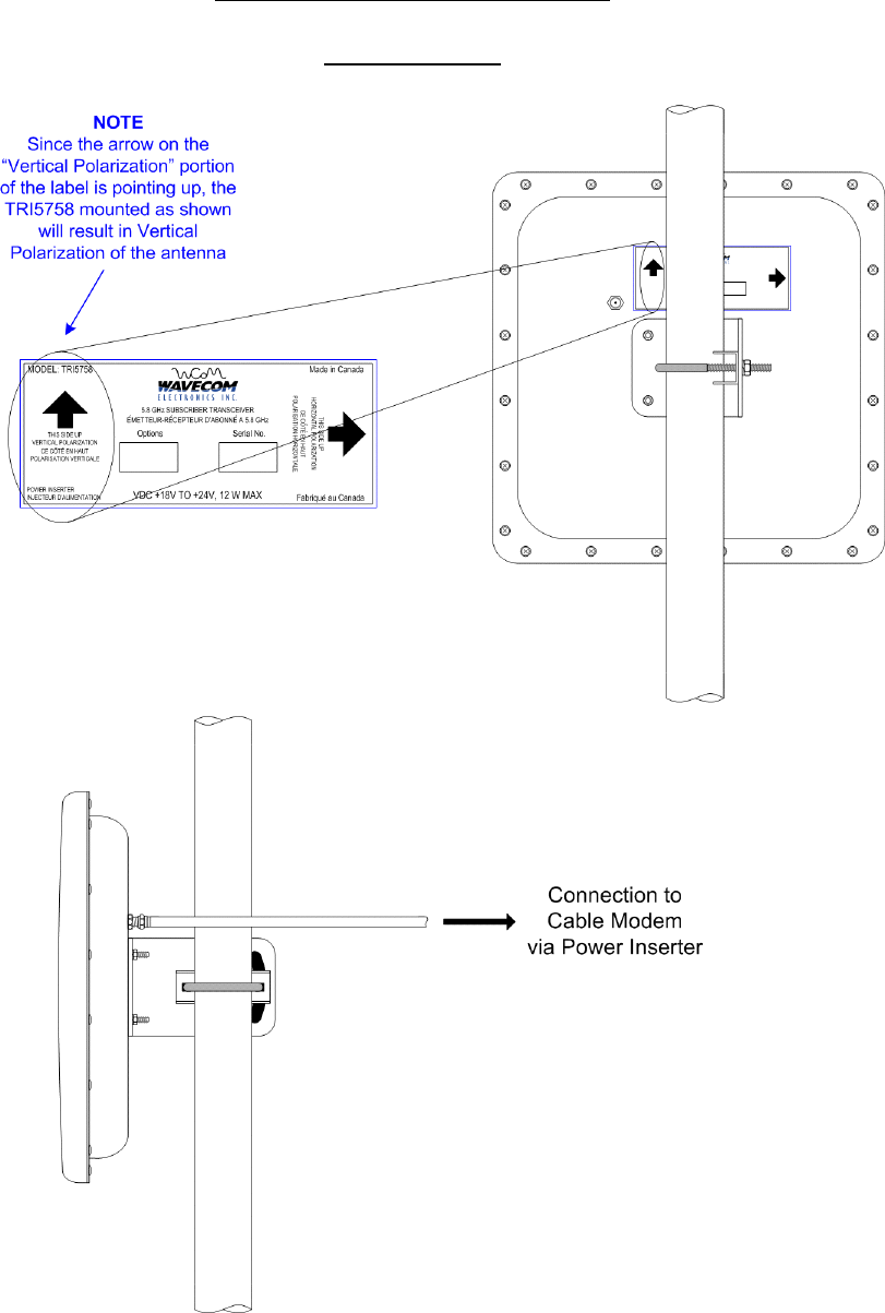
The active or desired polarization is the one in which the arrow points up. For example, when the TRI5758 is
mounted on the pole, if the arrow pointing up on the back of the TRI5758 says “Horizontal Polarization” then the
horizontal polarization is the active polarization. When the TRI5758 is mounted on the pole, if the arrow pointing
up on the back of the TRI5758 says “Vertical Polarization”, the vertical polarization is the active polarization
Secure the L-bracket to the cover using the #10-32 locknuts.
WaveCom Electronics Inc
TRI5758 Manual; ML_TRI5758_03 (June 2003)
Approval Pending
10
D
IAGRAM
2.2
A
: L-B
RACKET
O
RIENTATION
Once the L-bracket is in place, the unit can be mounted to the pole. The pole catch, V-bolt and L-bracket are
oriented as shown in Diagrams 2.2
B
and 2.2
C
.
WaveCom Electronics Inc
TRI5758 Manual; ML_TRI5758_03 (June 2003)
Approval Pending
11
D
IAGRAM
2.2
B
: TRI5758 M
OUNTED TO
P
OLE
Horizontal Alignment
WaveCom Electronics Inc
TRI5758 Manual; ML_TRI5758_03 (June 2003)
Approval Pending
12
D
IAGRAM
2.2
C
: TRI5758 M
OUNTED TO
P
OLE
Vertical Alignment
WaveCom Electronics Inc
TRI5758 Manual; ML_TRI5758_03 (June 2003)
Approval Pending
13
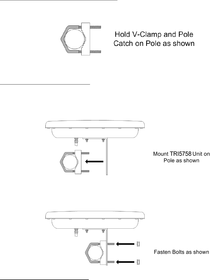
STEP 2 – Position V-bolt and pole catch around pole
To attach the TRI5758 to the pole, first position the pole catch over the threads of the V-bolt and hold against the
pole with one hand.
STEP 3 – Position TRI5758 against pole
Using the other hand, bring the TRI5758 up to the pole catch and grab V-bolt, pole catch and L-bracket in a single
hand. Ensure that the pole is inside the “L” of the L-bracket and not on the outside of the L. This is necessary to
maintain antenna alignment during high winds.
STEP 4 – Tighten TRI5758 against pole
Tighten both ¼” locknuts against the L-bracket so that the unit is held against the pole but can still be rotated and
tilted up and down for antenna alignment. The locknut closest to the antenna can be tightened almost all the way
while the back one should be approximately finger tight.
WaveCom Electronics Inc
TRI5758 Manual; ML_TRI5758_03 (June 2003)
Approval Pending
14
+*,+&-
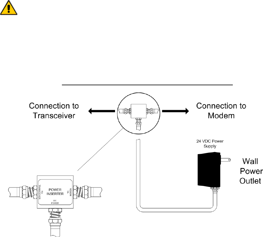
Connections to the TRI5758 are made as shown in Diagram 2.3A
Please note:
1) Connect the TRI5758 F-Connector to the power inserter, located indoors with the cable modem. The power
inserter is then connected to the Cable Modem, only after the antenna is aligned. The power inserter has
three connections:
DC POWER Connect to wall adapter with the supplied RG-59 cable with F connectors
TO MODEM Connect to cable modem (install modem only after the antenna is aligned)
TO TRANSCEIVER Connect to TRI5758
WARNING!
If the power inserter is incorrectly connected, the TRI5758 will not operate, and the
cable modem could be damaged.
Ensure that the unit is connected in the fashion shown in Diagram 2.3A before
plugging in the wall adapter.
2) After connection, the F connector on the TRI5758 must be waterproofed with the supplied rubber sealing tape.
See section 2.4 for details.
D
IAGRAM
2.3A: C
ONNECTION TO
C
ABLE
M
ODEM VIA
P
OWER
I
NSERTER
WaveCom Electronics Inc
TRI5758 Manual; ML_TRI5758_03 (June 2003)
Approval Pending
15
. / !")+
Many transceiver problems can be attributed to environmental conditions (including vibration), which can loosen cables
and permit moisture to penetrate the connectors. It is highly recommended that the connectors be sealed using a
technique similar to the one described below. This will provide moisture protection and keep the connections tight. For
your convenience, WaveCom has provided a 6” (15 cm) length of rubber self-amalgamating sealing tape to use on the
outdoor connection of the TRI5758.
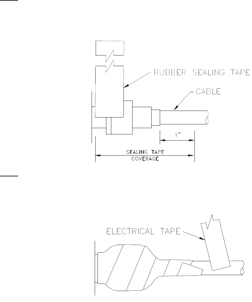
Step 1
Use a 6” section of rubber sealing tape. Starting at the TRI5758 end, stretch the tape and wrap it around the connector
as close as possible to the wall of the TRI5758. Overlap the tape by approximately one-half of its width so that it can
form a seal with itself. Extend the wrapping to approximately one-inch past the end of the connector.
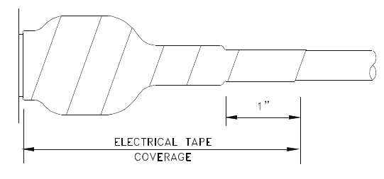
Step 2
Cover the sealing tape with electrical tape (not provided). Start approximately one inch further down the cable, and
stretch the tape, overlapping by one-half. Wrap to the TRI5758 end and without breaking the tape, wrap back down to
the cable end.
WaveCom Electronics Inc
TRI5758 Manual; ML_TRI5758_03 (June 2003)
Approval Pending
16
When done, the connection should be tightly wrapped with tape, with a good seal to the cable.

WaveCom Electronics Inc
TRI5758 Manual; ML_TRI5758_03 (June 2003)
Approval Pending
17
'0
) )*)1 !
When the unit is first powered up; or power-cycled any time thereafter; an audible signal strength indicator
(beeper) will be activated.
Fast beeping indicates a high relative signal strength, whereas slow beeping indicates that the unit requires
peaking.
Adjust the unit first panning left and right, then up and down until the rate of beeping is maximized. If the unit is
difficult to tilt or turn, loosen the locknuts on the V-bolts slightly.
If the beep rate is very quick this means the antenna alignment is optimal. At this point it is recommended that a
portable signal analyzer be used to further fine-tune the antenna alignment. Once antenna alignment is complete,
tighten the locknuts to secure the TRI5758 to the pole. If the signal strength is now optimized within acceptable
modem receive levels the beeping will stop after approximately 5 minutes or less.
If the beeping rate continues to remain low this may indicate a potential line of sight, distance limitation, and/or a
CPE or Base Station RF issue. Try installing the unit in a different location with a better/higher line of sight if
possible.
If the beeping quits at any time during tuning, simply power-cycle the unit to reactivate the beeper.
*')
To reset the timer for alignment, simply unplug the power supply from its AC connection. Wait 5 seconds, then
plug the power supply back into its AC connection. The beeper will begin beeping as soon as power is available.

WaveCom Electronics Inc
TRI5758 Manual; ML_TRI5758_03 (June 2003)
Approval Pending
18
. / 2 3 4 +,+
. / 5 -
WaveCom warrants its products to be free from defects in workmanship or materials for a period of two years. The
warranty begins on the date of the original shipment from WaveCom to its customer. No claim may be allowed for
expenses incurred in installation or use. No other expressed or implied warranties shall apply to the goods sold.
WaveCom is not responsible for delayed shipments, other loss beyond WaveCom’s control, or consequential
damages of any kind arising in connection with the use of its products. This warranty is a return-to-factory
warranty only. During the warranty period WaveCom will at its option, replace, repair or refund the price paid for
any item which is returned for service. This warranty does not apply to units that have been physically or
environmentally abused.
. ,6 0 -" 6
Before returning any item for service, an R.M.A. (Returned Material Authorization) number must be assigned by
WaveCom. A unique R.M.A. number will be assigned for each item being returned. When requesting an R.M.A.
number, please be prepared to provide the model, WaveCom serial number, original invoice number, your
purchase order number and an adequate fault description. The serial number of a unit can be found on a barcode
label similar to the one pictured below. R.M.A. service is available Monday to Friday from 8:30 a.m. to 4:30 p.m.
CST (statutory holidays excepted).
To obtain an R.M.A. number you may:
Call: (306) 955-7075, press ‘0’ for Operator, or ‘3’ for Service Dept.
Fax: (306) 384-0086 — Attention: R.M.A. Request
Email: support@WaveCom.ca
Once an R.M.A. number has been assigned, please refer to it in all correspondence and make certain that all
applicable R.M.A. numbers are clearly marked on the outside of each package being returned. You must also
ensure that each product is shipped to WaveCom in its original shipping container (or equivalent) via Prepaid
carrier, with appropriate insurance and customs documentation (where required). WaveCom will not accept collect
shipments, damaged shipments or shipments unaccompanied by an R.M.A. number.
For items still under Warranty –
Items will be returned from WaveCom Electronics Inc. to its customer via
prepaid ground carrier. The customer is responsible for any additional costs incurred, including custom clearance
and duties. Any alternate means of shipment must be requested by the customer and will be subject to additional
charges.
For items no longer under Warranty –
Items will be returned from WaveCom Electronics Inc. to its customer
via prepaid ground carrier at the customer’s expense. The customer is responsible for any additional costs
incurred, including custom clearance and duties. Any alternate means of shipment must be requested by the
customer and will be subject to additional charges.
Shipping Instructions will be provided by the repair center when the RMA number is sent to the customer.
WaveCom Electronics Inc
TRI5758 Manual; ML_TRI5758_03 (June 2003)
Approval Pending
19
. !+*)/ 5 7 -!
Items returned beyond the warranty period or items that do not qualify for warranty service are subject to additional
out-of-warranty repair charges. Descriptions of these charges and warranty exemptions are below:
1) Repair turnaround time is typically 5-14 business days after receipt of the item at WaveCom. A Flat Rate Repair
Charge will apply to all out-of-warranty items. Flat Rate Repair Charges are subject to change without notice.
2) Any faults due to customer error (ie - incorrect set-up or configuration settings) are subject to the current
Test Fee and will be exempt from warranty.
3) Items returned with inadequate fault descriptions are subject to the current Test Fee and are
exempt from warranty.
4) In the event that no fault is found, the item is subject to the current Test Fee and will be
exempt from warranty.
5) Any product exhibiting external damage (either from shipping, improper handling or use) will be subject to
inspection. If said damages are determined to be the cause of failure, the item will be exempt from warranty.
All repairs to correct the external damage are subject to Time & Materials Charges (parts and labor at current
rates).
6) Items with damage caused by unauthorized repairs or by external devices are subject to current out-of-warranty
Flat Rate Repair Charges and are exempt from warranty.
7) All products returned for Factory Optioning are subject to the applicable current Option Charge plus Test Fee.
Factory-optioned products carry the balance of the original warranty or a 90 day warranty, whichever is greater.
All out-of-warranty repairs must be approved by the customer in writing. No repairs will be made until the
customer’s Purchase Order or Out-Of-Warranty Repair Authorization is received.

150 Cardinal Place
Saskatoon, Saskatchewan
S7L 6H7
Canada
Tel: (306) 955-7075
Fax: (306) 955-9919
www.WaveCom.ca
sales@WaveCom.ca