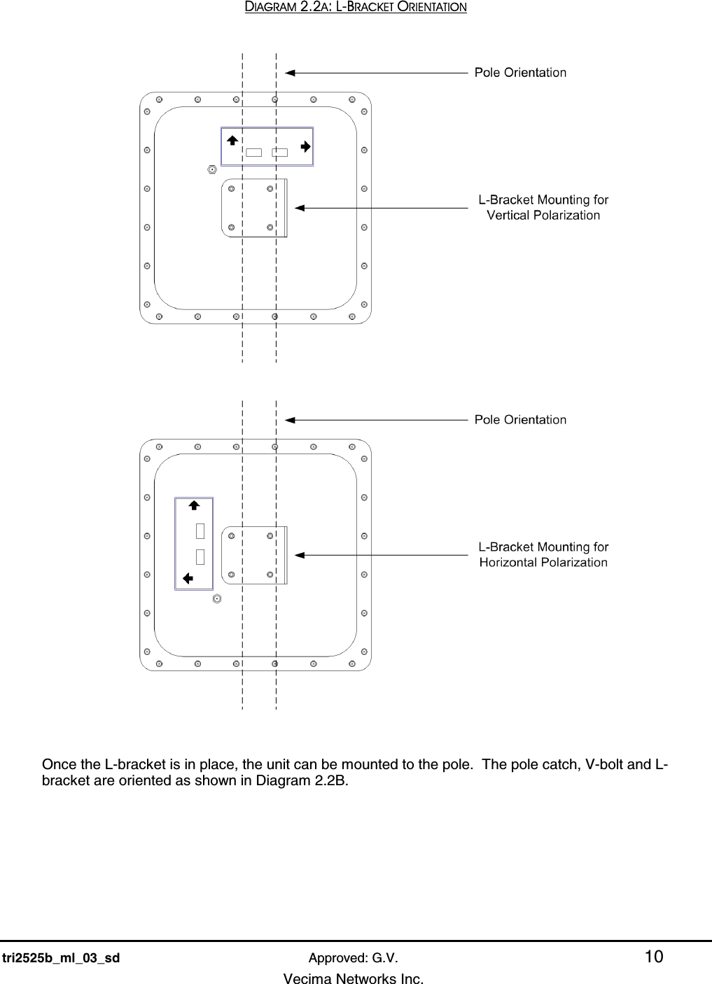
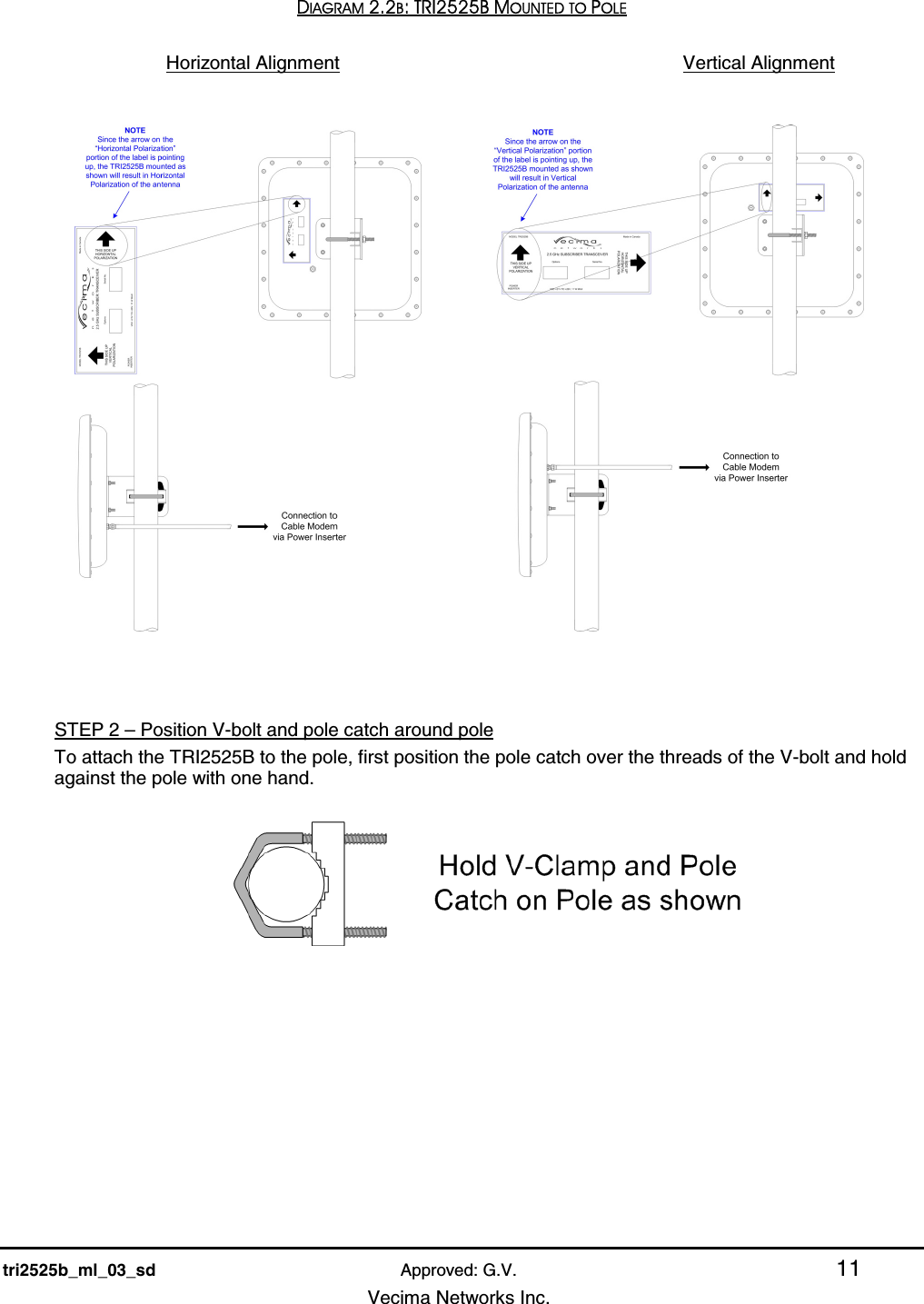
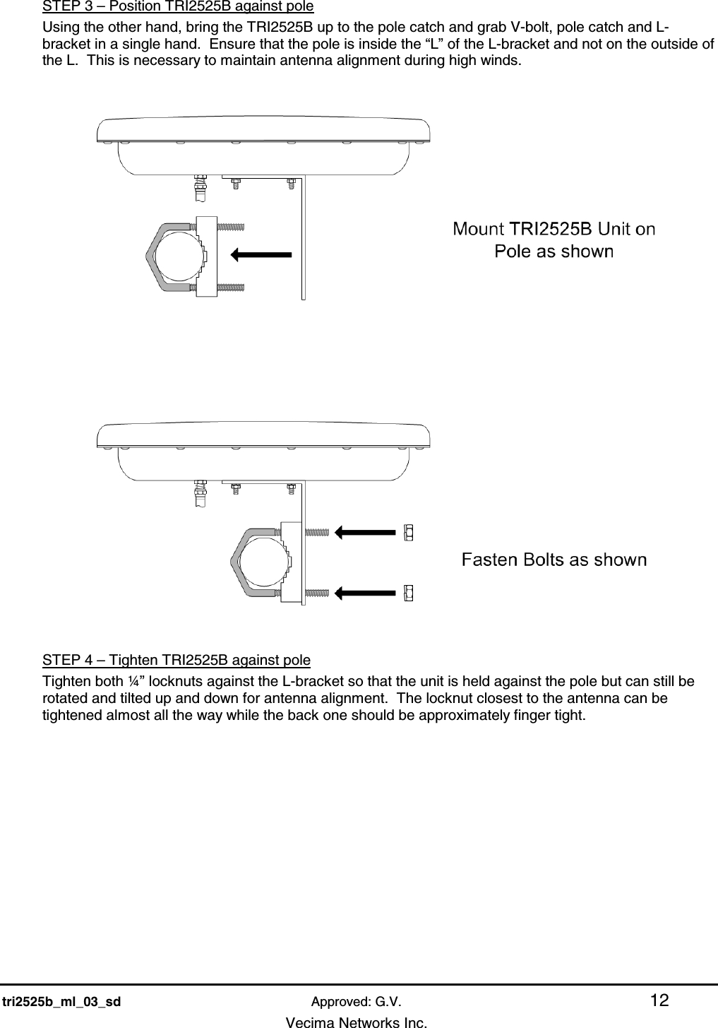
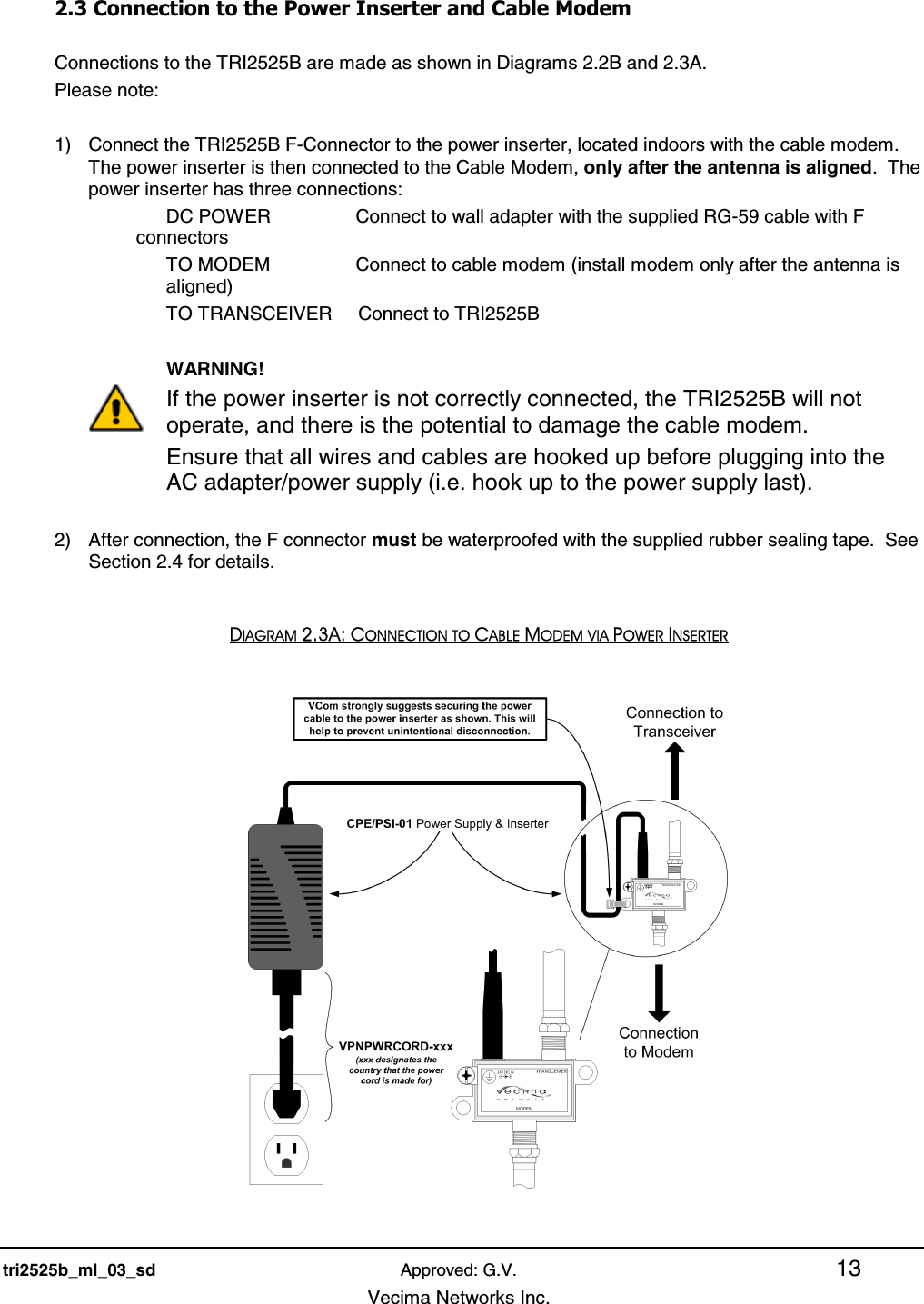
Vecima Networks TRX2525Y TRX2525Y 2.5-2.6 GHz Series Broadband Wireless Tx User Manual tri2525b ml 03 sd

Vecima Networks Inc. TRX2525Y 2.5-2.6 GHz Series Broadband Wireless Tx tri2525b ml 03 sd

User Manual

     TRI2525B 2.5 – 2.6 GHZ SERIES BROADBAND WIRELESS TRANSCEIVER  INSTALLATION AND OPERATION GUIDE
   tri2525b_ml_03_sd Approved: G.V. ii   Vecima Networks Inc.                               Document:  tri2525b_ml_03_sd Approved:  G.V.  Proprietary to Vecima Networks Inc. All rights reserved. No part of this publication may by reproduced in any form or by any means or used to make any derivative work (such as translation, transformation or adaptation) without written permission from Vecima Networks Inc. Vecima Networks Inc. reserves the right to revise this publication and to make changes in content from time to time without obligation on the part of Vecima Networks Inc. to provide notification of such revision or change. Vecima Networks Inc. provides this guide without warranty of any kind, either implied or expressed, including, but not limited to, the implied warranties of merchantability and fitness for a particular purpose. Vecima Networks Inc. may make improvements or changes in the product(s) described in this manual at any time. Specifications subject to change without notice — Printed in Canada
   tri2525b_ml_03_sd Approved: G.V. iii   Vecima Networks Inc.   Thank you for purchasing this product from Vecima Networks!    Vecima Networks is a leading technology design center and provides innovative solutions for the ongoing video, voice and data delivery revolution.  Since 1988, our design powerhouse has created custom RF and digital products for technology leaders such as AT&T, Cisco Systems, Cogeco, Comcast and Cox Communications.  All Vecima Networks products benefit from this ground-breaking expertise.   Vecima Networks designs and manufactures: z 256 QAM Upconverters  z Digital Video Modulators  z Agile CATV Modulators z Frequency Translators   z Spread Spectrum Devices  z MMDS Transceivers z Off-air/CATV Demodulators  z Wireless Cable MMDS   z Wireless Cable LMDS z Edge Devices      z Video On Demand Products and more!    For additional product or corporate information, please contact Vecima Networks at:  Vecima Networks Inc. 150 Cardinal Place Saskatoon, SK Canada S7L 6H7 Tel: (306) 955-7075 Fax: (306) 955-9919 Web: www.vecimanetworks.com Email: sales@vecimanetworks.com
   tri2525b_ml_03_sd Approved: G.V. iv   Vecima Networks Inc. SAFETY PRECAUTIONS  1. Before installing and operating this equipment, read all Safety, Installation and Operating sections. Retain this manual for future reference. 2. Follow all instructions — Failure to do so may result in damage to the unit or severe personal injury. 3. The user should not attempt servicing. There are no user serviceable parts inside. Refer all servicing to factory qualified personnel. 4. Shock Hazard — An electrical shock hazard exists when the chassis cover is removed as is required to set internal controls. Always disconnect power from the unit before removing the cover. 5. Cleaning — Do not use liquid or aerosol cleaners. Use a damp cloth for cleaning. Warning Do not work on the system or connect or disconnect cables during periods of lightning activity. LES PRÉCAUTIONS DE SÉCURITÉ    1. Avant d'installer ou d'opérer cet équipement, lisez, toutes les sections de sécurités, d'installations et d'opérations.  Gardez ce manuel comme source de référence.  2. Suivez toutes instructions - si non, vous risquez d'endommager la machine ou de vous blesser sérieusement.  3. N'essayez, pas de réparer cet équipement vous même.  Référez toutes revisions nécessaire au personnel qualifié de la manufacture.  4. Risque de choc - Il y a un risque de décharge électrique qui existe quand la couverture du châssis est enlevée, comme est nécessaire pour ajuster les contrôlcs internes.  Il faut toujours couper l'électricité avant d'enlever le couvercle pour faire aucun ajustage.  5. Le nettoyage - n'utilisez pas de nettoyeurs aérosols ou liquides.  Utilisez un tissu humide pour nettoyer. Attention Ne pas travailler sur le système ni brancher ou débrancher les câbles pendant un orage du foudre.
   tri2525b_ml_03_sd Approved: G.V. v   Vecima Networks Inc. INDEX 1.0 GENERAL INFORMATION .......................................................................................................................... 7 1.1 Functional Overview ................................................................................................................................................... 7 1.2 Module Features .......................................................................................................................................................... 7 1.3 Specifications................................................................................................................................................................ 8 2.0 INSTALLATION ............................................................................................................................................. 9 2.1 Unpacking the Unit...................................................................................................................................................... 9 2.2 Mounting the Unit ....................................................................................................................................................... 9 2.3 Connection to the Power Inserter and Cable Modem ............................................................................................ 13 2.4 Waterproofing Connections...................................................................................................................................... 14 3.0 ALIGNING THE ANTENNA ....................................................................................................................... 16 3.1 Preparation for Tuning............................................................................................................................................. 16 3.2 Signal Strength and Alignment ................................................................................................................................ 16 3.3 Resetting the Beeper .................................................................................................................................................. 16 4.0 WARRANTY AND SERVICE POLICIES ................................................................................................... 17 4.1 Warranty Statement.................................................................................................................................................. 17 4.2 Service Policies: How to Return an Item for Service: ............................................................................................ 17 4.3 Repair Charges and Warranty Exemptions............................................................................................................ 18
   tri2525b_ml_03_sd Approved: G.V. vi   Vecima Networks Inc.
   tri2525b_ml_03_sd Approved: G.V. 7   Vecima Networks Inc.  1.0 GENERAL INFORMATION  1.1 Functional Overview  The Vecima Networks TRI2525B is an outdoor RF transceiver for use in broadband wireless systems.  The TRI2525B combines a low noise downconverter, high power upconverter, antenna and high rejection duplexer to offer a fully integrated solution for 3.5 GHz subscriber terminals.  The TRI2525B integrated subscriber transceiver serves to frequency translate and amplify the upstream and downstream signals to the appropriate intermediate frequencies for use by the indoor DOCSIS modem. The TRI2525B and antenna are situated outdoors and connected to a cable modem indoors by a low cost 75 ohm cable (i.e. RG-59, RG-6 or similar).  A single RF F-connector on the weatherproofed enclosure provides the interface to the transmit/receive antenna for rapid installation. 1.2 Module Features  •  High Output Power: Up to +39 dBm EIRP with QPSK •  Automatic transmit RF mute when modem is not transmitting •  Low Noise: < 7 dB typical •  Temperature compensation to guarantee specifications over full operating temperature range •  All local oscillators are frequency synthesized and locked to a common internal high stability reference •  Integrated planar antenna (15° beamwidth, 18 dBi gain) •  High reliability, state-of-the-art design using microstrip, MMIC and surface mount technology •  Conservative component derating and 100% burn in help ensure reliable operation •  Fully weatherized unit, suitable for outdoor mounting •  Audible installation alignment beeper; to facilitate customer self install
   tri2525b_ml_03_sd Approved: G.V. 8   Vecima Networks Inc. 1.3 Specifications  Subscriber Transceiver Specifications TRANSMIT SPECIFICATIONS IF Input Frequency    18 to 42 MHz* Automatic Mute Threshold Level    -47 dBm Automatic Mute Response Time    < 1.2 microseconds RF Frequency Range    2500 to 2524 MHz* Rated Output Power    16QAM: +37 dBm; QPSK: +39dBm Integrated Gain     33 ± 1dB Gain Flatness    ±1dB peak to peak Gain Stability    ±2 dB over temperature Spectral Mask    FCC CFR 47 Part 21 / Industry Canada RSS193 Phase Noise    <-90 dBc / Hz at 10 kHz         <-45 dBc integrated over 10 kHz to 2.5 MHz Frequency Setting and Stability    ±5.0 kHz Frequency Stability over 10 years    ±10 kHz RECEIVE SPECIFICATIONS RF Frequency Range    2566 to 2596 MHz* Frequency Response (any 6 MHz band)    ±0.5 dB IF Output Frequency Range    534 to 564 MHz* Noise Figure    5.5dB typical <7 dB max including narrowband duplexer loss  Integrated Gain    44 ± 1dB Input Third Order Intercept Point    -7 dBm at LNA input Interference Sensitivity    As per ETSI EN 301 021 section 5.4.4.3 when used in conjunction with         DOCSIS certified modems Phase Noise    <-90 dBc / Hz at 10 kHz         <-45 dBc integrated over 10 kHz at 2.5 MHz Frequency Setting and Stability    ±5.0 kHz Frequency Stability over 10 years    ±10 kHz GENERAL  IF Connector    F female, 75 ohms IF Return Loss    10 dB Power Requirement    +21 to +28 VDC Power Consumption    11 W maximum Operating Temperature Range    -40 to +55°C ambient full specifications  Antenna Gain    16 dBi minimum Antenna Beamwidth    15° typical Antenna Compliance    RSS193 Spurious Emissions    RSS193 EMC Compliance    RSS193 Dimensions     12” x 12” x 2.5” (305mm x 305mm x 64 mm) maximum Weight       7 lbs. (3.2 kg)     Specifications subject to change without notice.
   tri2525b_ml_03_sd Approved: G.V. 9   Vecima Networks Inc. 2.0 INSTALLATION  2.1 Unpacking the Unit  Carefully remove the equipment from its packing material and set it on a solid surface, such as a table or desk. If it appears damaged in any way, notify the carrier, and keep all packing materials for inspection by the carrier’s agent. 2.2 Mounting the Unit  The following hardware is included in the box for mounting the brackets to the pole: •  1 L-bracket (taped to one of the foam pieces inside the box)          •  1 pole catch    • 1 V-bolt  •  4 #10-32 flange locknuts for connecting L-bracket to cover   •  2 ¼ - 20 flange locknuts for connecting V-bolt and pole catch to the pole   The TRI2525B was designed for mounting on a pole with a diameter of 1.0” to 1.75”.  Please ensure that the pole used is attached securely to the building or other mounting location.    Step 1 – Attach L-Bracket to TRI2525B Before the unit can be attached to the pole, the L-bracket must be attached in the correct orientation according to the polarization required for the particular customer installation.  Diagram 2.2A shows the orientation of the bracket relative to the cover for both horizontal and vertical polarization.    The active or desired polarization is the one in which the arrow points up.  For example, when the TRI2525B is mounted on the pole, if the arrow pointing up on the back of the TRI2525B says “Horizontal Polarization” then the horizontal polarization is the active polarization.  When the TRI2525B is mounted on the pole, if the arrow pointing up on the back of the TRI2525B says “Vertical Polarization”, the vertical polarization is the active polarization  Secure the L-bracket to the cover using the #10-32 locknuts.
   tri2525b_ml_03_sd Approved: G.V. 10   Vecima Networks Inc.  DIAGRAM 2.2A: L-BRACKET ORIENTATION     Once the L-bracket is in place, the unit can be mounted to the pole.  The pole catch, V-bolt and L-bracket are oriented as shown in Diagram 2.2B.
   tri2525b_ml_03_sd Approved: G.V. 11   Vecima Networks Inc. DIAGRAM 2.2B: TRI2525B MOUNTED TO POLE  Horizontal Alignment             Vertical Alignment             STEP 2 – Position V-bolt and pole catch around pole To attach the TRI2525B to the pole, first position the pole catch over the threads of the V-bolt and hold against the pole with one hand.
   tri2525b_ml_03_sd Approved: G.V. 12   Vecima Networks Inc. STEP 3 – Position TRI2525B against pole Using the other hand, bring the TRI2525B up to the pole catch and grab V-bolt, pole catch and L-bracket in a single hand.  Ensure that the pole is inside the “L” of the L-bracket and not on the outside of the L.  This is necessary to maintain antenna alignment during high winds.      STEP 4 – Tighten TRI2525B against pole Tighten both ¼” locknuts against the L-bracket so that the unit is held against the pole but can still be rotated and tilted up and down for antenna alignment.  The locknut closest to the antenna can be tightened almost all the way while the back one should be approximately finger tight.
   tri2525b_ml_03_sd Approved: G.V. 13   Vecima Networks Inc. 2.3 Connection to the Power Inserter and Cable Modem  Connections to the TRI2525B are made as shown in Diagrams 2.2B and 2.3A.   Please note:  1)  Connect the TRI2525B F-Connector to the power inserter, located indoors with the cable modem. The power inserter is then connected to the Cable Modem, only after the antenna is aligned.  The power inserter has three connections: DC POWER       Connect to wall adapter with the supplied RG-59 cable with F connectors TO MODEM       Connect to cable modem (install modem only after the antenna is aligned) TO TRANSCEIVER     Connect to TRI2525B         WARNING! If the power inserter is not correctly connected, the TRI2525B will not operate, and there is the potential to damage the cable modem.   Ensure that all wires and cables are hooked up before plugging into the AC adapter/power supply (i.e. hook up to the power supply last).  2)  After connection, the F connector must be waterproofed with the supplied rubber sealing tape.  See Section 2.4 for details.  DIAGRAM 2.3A: CONNECTION TO CABLE MODEM VIA POWER INSERTER
   tri2525b_ml_03_sd Approved: G.V. 14   Vecima Networks Inc. 2.4 Waterproofing Connections  This will provide moisture protection and keep the connections tight.  Vecima Networks has provided a 6-inch length of rubber self-amalgamating sealing tape to use on the TRI2525B F-connector.    Step 1 Use a 6” section of rubber sealing tape.  Starting at the TRI2525B end, stretch the tape and wrap it around the connector as close as possible to the wall of the TRI2525B.  Overlap the tape by approximately one-half of its width so that it can form a seal with itself.  Extend the wrapping to approximately one-inch past the end of the connector.   Step 2 Cover the sealing tape with electrical tape (not provided).  Start approximately one inch further down the cable, and stretch the tape, overlapping by one-half.  Wrap to the TRI2525B end and without breaking the tape, wrap back down to the cable end.
   tri2525b_ml_03_sd Approved: G.V. 15   Vecima Networks Inc. When done, the connection should be tightly wrapped with tape, with a good seal to the cable.
   tri2525b_ml_03_sd Approved: G.V. 16   Vecima Networks Inc. 3.0 ALIGNING THE ANTENNA  3.1 Preparation for Tuning Before tuning the antenna insure that the cable modem is not connected to the power inserter. The cable modem signal will prevent the signal strength indicator from responding to very weak receive signals. 3.2 Signal Strength and Alignment The TRI2525B is equipped with an audible alignment aid that simplifies the setup process.  It permits alignment to the hub site without the use of the cable modem or any test equipment. The aid consists of a level detector for the full receive band, and a beeper sealed into the unit that sounds at a rate that increases with increasing level.  The beeper is activated only for about 3 to 10 minutes each time power is applied to the TRI2525B. To use the aid, first mount the TRI2525B.  If the unit is difficult to tilt or turn, loosen the locknuts on the V-bolts slightly.   Apply power to the TRI2525B when you are ready to begin.  The beeper will start sounding.  Point the TRI2525B in the general direction of the hub site, then move it to maximize the rate of the beeper.  The highest rate heard represents the highest receive signal level and the best alignment.  Once the antenna alignment is complete, tighten the locknuts to secure the TRI2525B to the pole.  The beeper will automatically mute between 3 and 10 minutes after the unit was powered up, turning off faster with higher received signal level. The detector operates over a wide level range.  Installations that are closer to the hub site and consequently receive a larger signal will have a higher beep rate than an installation further out.  In each case, finding the alignment with the highest beep rate indicates the best alignment.   Note that the TRI2525B alignment aid does not discriminate between signals in the receive band.  If signals other than those from the hub are present, this could result in a misalignment.  In this case, a conventional alignment technique would need to be employed. 3.3 Resetting the Beeper To reset the timer for alignment, simply unplug the power supply from its AC connection. Wait 5 seconds, and then plug the power supply back into its AC connection. The beeper will begin beeping as soon as power is available.
   tri2525b_ml_03_sd Approved: G.V. 17   Vecima Networks Inc. 4.0 WARRANTY AND SERVICE POLICIES 4.1 Warranty Statement Vecima Networks warrants its products to be free from defects in workmanship or materials for a period of two years.  The warranty begins on the date of the original shipment from Vecima Networks to its customer.  No claim may be allowed for expenses incurred in installation or use.  No other expressed or implied warranties shall apply to the goods sold. Vecima Networks is not responsible for delayed shipments, other loss beyond Vecima Networks’ control, or consequential damages of any kind arising in connection with the use of its products.  This warranty is a return-to-factory warranty only.  During the warranty period Vecima Networks will at its option, replace, repair or refund the price paid for any item which is returned for service.  This warranty does not apply to units that have been physically or environmentally abused.  4.2 Service Policies: How to Return an Item for Service: Before returning any item for service, an R.M.A. (Returned Material Authorization) number must be assigned by Vecima Networks.  A unique R.M.A. number will be assigned for each item being returned.  When requesting an R.M.A. number, please be prepared to provide the model, Vecima Networks serial number, original invoice number, your purchase order number and an adequate fault description.  The serial number of a unit can be found on a barcode label similar to the one pictured below.  R.M.A. service is available Monday to Friday from 8:30 a.m. to 4:30 p.m. CST (statutory holidays excepted).     To obtain an R.M.A. number you may: Call: (306) 955-7075, press ‘0’ for Operator, or ‘3’ for Service Dept. Fax: (306) 384-0086 — Attention: R.M.A. Request Email: support@vecimanetworks.com  Once an R.M.A. number has been assigned, please refer to it in all correspondence and make certain that all applicable R.M.A. numbers are clearly marked on the outside of each package being returned.  You must also ensure that each product is shipped to Vecima Networks in its original shipping container (or equivalent) via Prepaid carrier, with appropriate insurance and customs documentation (where required).  Vecima Networks will not accept collect shipments, damaged shipments or shipments unaccompanied by an R.M.A. number.  For items still under Warranty – Items will be returned from Vecima Networks Inc. to its customer via prepaid ground carrier.  The customer is responsible for any additional costs incurred, including custom clearance and duties.  Any alternate means of shipment must be requested by the customer and will be subject to additional charges.   For items no longer under Warranty – Items will be returned from Vecima Networks Inc. to its customer via prepaid ground carrier at the customer’s expense.  The customer is responsible for any additional costs incurred, including custom clearance and duties.  Any alternate means of shipment must be requested by the customer and will be subject to additional charges.  Shipping Instructions will be provided by the repair center when the RMA number is sent to the customer.
   tri2525b_ml_03_sd Approved: G.V. 18   Vecima Networks Inc. 4.3 Repair Charges and Warranty Exemptions Items returned beyond the warranty period or items that do not qualify for warranty service are subject to additional out-of-warranty repair charges.  Descriptions of these charges and warranty exemptions are below: 1) Repair turnaround time is typically 5-14 business days after receipt of the item at Vecima Networks. A Flat Rate Repair Charge  will apply to all out-of-warranty items.  Flat Rate Repair Charges are subject to change without notice. 2) Any faults due to customer error (i.e. - incorrect set-up or configuration settings) are subject to the current  Test Fee and will be exempt from warranty. 3) Items returned with inadequate fault descriptions are subject to the current Test Fee and are  exempt from warranty. 4) In the event that no fault is found, the item is subject to the current Test Fee and will be  exempt from warranty. 5) Any product exhibiting external damage (either from shipping, improper handling or use) will be subject to inspection.  If said damages are determined to be the cause of failure, the item will be exempt from warranty. All repairs to correct the external damage are subject to Time & Materials Charges (parts and labor at current rates). 6) Items with damage caused by unauthorized repairs or by external devices are subject to current out-of-warranty  Flat Rate Repair Charges and are exempt from warranty. 7) All products returned for Factory Optioning are subject to the applicable current Option Charge plus Test Fee.   Factory-optioned products carry the balance of the original warranty or a 90 day warranty, whichever is greater. All out-of-warranty repairs must be approved by the customer in writing.  No repairs will be made until the customer’s Purchase Order or Out-Of-Warranty Repair Authorization is received.
                                               150 Cardinal Place Saskatoon, Saskatchewan, Canada S7L 6H7 Tel: (306) 955-7075 Fax: (306) 955-9919 Web: www.vecimanetworks.com Email: sales@vecimanetworks.com

Navigation menu